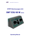
1
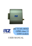
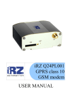
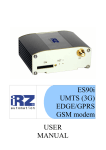
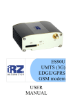
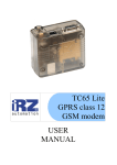
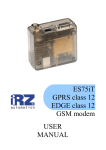
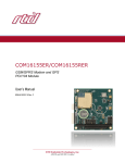
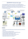
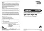
IRZ MC55i-485GI
GPRS class 10
GSM modem
USER
MANUAL
GSM modem IRZ MC55i-485GI
User Manual
1.
2.
Contents
Safety Requirements ............................................................................................................................................ 3
General Information ............................................................................................................................................. 4
2.1. Purpose of the Device ......................................................................................................................................... 4
2.2. Configuration ..................................................................................................................................................... 4
2.3. Parameters.......................................................................................................................................................... 4
2.4. Exterior Appearance ........................................................................................................................................... 6
2.5. Interfaces............................................................................................................................................................ 7
2.5.1. Disruptive Terminal Connector ........................................................................................................................ 7
2.5.2. Connector RJ11 for Electric Power Supply Connection .................................................................................... 8
2.6. Modem Status Indication .................................................................................................................................... 9
3.
Connection and Setting Up................................................................................................................................. 10
3.1.
Connection ............................................................................................................................................... 10
3.2.
Restarting and Power Off .......................................................................................................................... 10
3.3.
Menu Mode .............................................................................................................................................. 10
4.
Emergency Situations......................................................................................................................................... 13
4.1.
Emergency 1 (input voltage invalid).......................................................................................................... 13
4.2.
Emergency 2 (power supply of the module invalid) ................................................................................... 13
4.3.
Emergency 3 (GSM module not started).................................................................................................... 13
2
GSM modem IRZ MC55i-485GI
User Manual
1. Safety Requirements
Restrictions for the usage of the device in the vicinity of other electronic devices:
· turn off the modem IRZ MC55i-485GI in hospitals or in the vicinity of medical
equipment (e.g. cardiostimulators, hearing aids). It can cause interference for medical
equipment;
· turn off the modem in aircrafts. Take measures against accidental activation;
· turn off the modem in the vicinity of gas-filling stations, chemical enterprises, blasting
work places. It can cause interference to technical devices;
· at a short range the modem may cause harmful interference to TV and radio receivers.
Prevent the modem from dust and moisture.
Improper use deprives you of all warranty claims.
3
GSM modem IRZ MC55i-485GI
User Manual
2. General Information
2.1. Purpose of the Device
The modem IRZ MC55i-485GI is a structurally accomplished GSM modem designed for
reception and communication of data, text messages and telecopies. It is excellently adjusted for
industrial applications — telemetry, wireless data collection from sensors, remote monitoring and
signaling.
The modem is assembled based on the GSM module MC55i Cinterion. The control is performed
by means of standard AT-commands. The terminal is equipped with light-emitting diodes (LEDs) to
monitor the status of connection.
2.2. Configuration
The complete set of the GSM modem IRZ MC55i-485GI:
· terminal IRZ MC55i-485GI,
· label,
· factory box.
2.3. Parameters
Basic parameters:
· frequency ranges: GSM 850/900/1800/1900 mHz;
· power output:
o 2W (class 4 for EGSM900),
o 1W (class 1 for GSM1800),
· GPRS class 10;
· TCP/IP suit available through AT commands;
· MC class B;
· CSD up to 14.4 kbps;
· USSD;
· SMS;
· fax group 3: class 1.
Electric power supply:
· power supply voltage from 9 to 25 V;
· absorbed current not more than:
o with power supply voltage +12 V – 200 mA;
o with power supply voltage +24 V - 100 mA.
Physical parameters:
· size not more than 76х85х30 mm;
· weight not more than 130 g.;
· operating-temperature range from -20°С to +65°С.
4
GSM modem IRZ MC55i-485GI
User Manual
Interfaces:
· Connector RJ11 for power supply connection,
· Disruptive terminal connector for data cable connection (RS-485 and power supply
connection),
· Connector SMA for GSM antenna connection.
Electric power supply can be fed to any of the two first connectors.
5
GSM modem IRZ MC55i-485GI
User Manual
2.4. Exterior Appearance
The modem MC485 is a compact device made in a durable and lightweight aluminum housing.
The exterior appearance is represented on Fig.2.4.1 and Fig.2.4.2.
2
3
1
4
Fig.2.4.1 Front view
On the figures the digits mark the following:
1. Emergency LED indicator,
2. Network LED indicator,
3. SIM card tray extract button,
4. SIM card tray
6
GSM modem IRZ MC55i-485GI
User Manual
2.5. Interfaces
2.5.1. Disruptive Terminal Connector
The connector is used for connection of electric power supply and of the control device, exchange
protocol RS485.
Fig.2.5.1 Disruptive terminal connector
Table 2.5.1 Purpose of the connector pins.
Connectors
Signal
Purpose
1
+Vin
“+” of the power supply source
2
-Vin
“-” of the power supply source
3
SHLD
“Screen” RS-485
4
“B”
“d-“ RS-485;
5
“A”
“d+“ RS-485;
6
+5V
”+5V” RS-485.
7
GSM modem IRZ MC55i-485GI
User Manual
2.5.2. Connector RJ11 for Electric Power Supply Connection
The connector is used for connection of electric power supply.
1
2
3
4
5
6
Fig.2.5.2 Connector RJ11
Table 2.5.2 Purpose of power supply connector pins.
Contact
Signal
Purpose
1
+ 12V
Positive pole of DC supply voltage. Protected with a fuse and the
voltage-surge protection circuit (with voltage infeed rate more than
30V) and incorrect polarity.
2
not used
3
not used
4
not used
5
not used
6
GND
System casing
8
GSM modem IRZ MC55i-485GI
User Manual
2.6. Modem Status Indication
Two LEDs are used for operating mode indication or for indication of emergency situations.
Table 2.6.1 Operating mode indication (green LED)
Indication mode
Operating mode
Turned off
Modem is turned off or there is an emergency situation
600 ms on / 600 ms
Modem is not registered in the network
off
75 ms on / 3 s off
Modem is registered in the network
75 ms on / 75 ms off / GPRS connection is installed
75 ms on / 3 s off
500 ms on / 50 ms off Data transmission is underway
250 ms on / 10 s off
Modem is in the power standby mode, alarm-clock mode.
250 ms on / 250 ms
Programming mode, menu mode
off
Table 2.6.2 Emergency situation indication (red LED)
Indication mode
Description of emergency
Continuously turned Input voltage invalid
on
0.5 s on / 0.5 s off
Power supply of the module invalid
0.25 s on / 0.25 s off / GSM module not started
0.25 s on / 1 s off
9
GSM modem IRZ MC55i-485GI
User Manual
3. Connection and Setting Up
3.1. Connection
Before feeding the power supply it is required to install the SIM card in the modem (the SIM
card must be enabled). To do this, you need:
· to extract the SIM tray by pressing the SIM tray extract button (Fig.2.4.1);
· to install the SIM card into the SIM tray;
· to insert the SIM tray with the SIM card into the modem.
No strong physical efforts must be applied while installing the SIM card.
Connect the GSM antenna to the antenna connector as well as the commutating cable (RS485).
Thereupon you need to feed power supply to the modem through the connector RJ11 (Fig.2.5.2) or
the disruptive connector (Fig.2.5.1).
Note: GSM antenna, commutating cables and electrical power unit are not included in the
complete set configuration.
After the power supply feeding, registration occurs automatically, which is signaled by the green
indicator frequent flashing. After the registration is completed, the modem jumps to the operating
mode, the green indicator flashes less frequently (Table 2.6.1).
3.2. Restarting and Power Off
The modem can be restarted in the following ways:
· restarting after a specified time period (WD interval, turned off on default), setting-up is
made in the menu mode;
· by temporary power-off.
Power off of the modem can be carried out using the following ways:
· by the program method, using AT commands (escape to the power standby mode);
· directly by power-off.
After power-off made by means of AT commands, the modem escapes to the power standby
mode (minimum power consumption). Escaping from the power standby mode is performed while
turning-on of the GSM module by the alarm clock.
3.3. Menu Mode
The menu mode is designed to change the modem parameters and browse the statistics. In the
menu mode the power supply of the GSM module is turned off, after escaping from the mode,
automatic start occurs. You can jump to the menu mode from the operating mode. Before starting,
connect the modem to the computer (rate is 115200 bit/sec, 8-N-1), feed the power supply to the
modem, start the Hyper Terminal or a similar program to communicate with the modem. After
extraction of the SIM tray (by pressing the SIM tray extract button), the modem will jump to the
menu mode. Herewith the main menu is to be represented:
Menu mode:
Variant XX
<P1> Show statistics
10
GSM modem IRZ MC55i-485GI
User Manual
<P2> WD interval = XXX hh (или “OFF”)
<PC> Power control
<PR> Clear statistic
where Variant XX is the weaving version.
The characters <…> signify the control commands. Input of the command gets underway after
pressing “Enter”. In case of incorrect input, “ERROR” is indicated. There is no difference between
the entered uppercase and lowercase characters.
After input of the command “P1” you jump to the statistics browsing menu:
Statistics:
Power_Modem = XX…X
Bad_Power_Modem = XX…X
Power_Module = XX…X
Bad_Power_Module = XX…X
Start_Module = XX…X
Bad_Start_Module = XX…X
Reset = XX…X
When the modem is used, the following situations are automatically saved:
Power_Modem – number of modem connexions,
Bad_Power_Modem – number of power supply deviations of the modem from the allowed
value,
Power_Module – number of power supply feedings to the GSM module,
Bad_Power_Module - number of power supply deviations of the GST module from the allowed
value,
Start_Module – number of successful GSM module starts,
Bad_Start_Module – number of situations where the GSM module did not start,
Reset – number of restartings.
After the statistics output, you will jump to the main menu.
After the input of the command “P2” you will jump to the WD menu:
WD interval, hh (hh=00 - WD off, max - 255)
<Q> Quit
WD interval =
In order to change the restarting interval, enter the number from 0 tо 255 (input is after pressing
«Enter»). The restarting interval is specified in hours. If you need to disable this function, enter 0.
You should consider that after expiration of the specified time interval the modem will be restarted
unconditionally. In case of incorrect input, the modem will indicate “ERROR” and represent the WD
menu again. If the restarting interval is entered successfully, or the “Q” command is given, you will
jump to the main menu.
After the input of the “PC” command – browsing of the input supply voltage and the module
supply voltage (measurement accuracy 5%):
P0WER Uin=12.0 Umd=3.9
After the output you will jump to the main many.
After the input of the “PR” command – you will jump to the statistics clearing menu:
Clear statistic?
<YES> YES
<Q> Quit
11
GSM modem IRZ MC55i-485GI
User Manual
The collected statistics is cleared by the command “YES”. In case of incorrect input, the modem
will indicate “ERROR” and represent the statistics clearing menu again. In case of successful
entering or input of the command <Q>, you will jump to the main menu.
After the input of the “M” command – the main menu will be loaded again.
You will escape from the menu mode after installation of the SIM tray.
12
GSM modem IRZ MC55i-485GI
User Manual
4. Emergency Situations
To simplify the use of the modem, tracking of emergencies is provided.
4.1. Emergency 1 (input voltage invalid)
Emergency 1 occurs in case of deviation of the input power supply voltage from the allowed
value. In such case the modem stops the operation: disconnects the power supply of the GSM
module. It signals with the red LED about the emergency situation (turned on continuously).
Escaping from the emergency situation is possible only after restoring of the input voltage.
4.2. Emergency 2 (power supply of the module invalid)
Emergency 2 arises in case of deviation of the power supply voltage of the GSM module from
the allowed value. In such case the modem stops its operation: disconnects the power supply of the
GSM module. It signals with the red LED about the emergency situation (0.5 s on / 0.5 s off).
Escaping from the emergency situation is possible only after restoring of the power supply voltage
of the module within 10 seconds from the time when the emergency situation occurred. If the power
supply voltage of the module stays incorrect within 10 seconds (with correct input voltage), the
modem jumps to the standby mode – the module power supply is disconnected, the emergency
indication persists. Escaping from the standby mode is possible only after full disconnection of
power supply.
In case of any repeated emergency after restarting of the modem, the modem is to be repaired.
4.3. Emergency 3 (GSM module not started)
Emergency 3 occurs in case where the GSM module is not started. Red LED signaling about the
emergency situation: 0.25 s on / 0.25 s off / 0.25 s on / 1 s off. Escaping from the emergency
situation is possible only after successful start of the GSM module. In case of 10 consecutive failed
attempts to start the module (15 seconds), the modem jumps to the standby mode – the module
power supply is disconnected, the emergency indication persists. Escaping from the standby mode is
possible only with full disconnection of the power supply.
In case of any repeated emergency after restarting of the modem, the modem is to be repaired.
13