1
Index
definition of, 1-1
expected life, A-2
front connector, 1-3
functional overview, 2-2
general purpose relays, 2-4
module block diagram, 2-3
operate and release times, 2-4
operation, 2-1
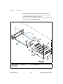
parts locator diagram, B-2
routing signals, 1-1
safety instructions, 2-1
switch architecture, C-2
technical support form, E-3, E-5
NI-Spy utility, D-1
NI-SWITCH driver software, 1-4, D-2
features of, 1-4
NI-SWITCH Software User Manual, 2-7, D-1,
D-2
number of relays, A-1
installation
of diode varistor, B-1
of NI 2565 module, B-1
insulation
coordination of, 1-2
rating, A-3
reinforced, 1-2
insulator (in Parts Locator Diagram), B-2
interrupt handling, 1-4
IVI (Interchangeable Virtual Instrument), 1-4
definition of, G-3
L
LabVIEW, 1-4
LabVIEW NI-SWITCH VI Library, 1-4
LabWindows/CVI, 1-4
LabWindows/CVI NI-SWITCH Library, 1-5
M
O
master switch card, 2-7
maximum altitude (environment), A-3
maximum switching
capacity per channel, A-1
exceeding capability, A-2
power per channel, A-1
rate (dynamic characteristics), A-2
voltage, A-1
modes, 2-6
module block diagram, 2-3
multicard triggering, 2-7
onboard control logic
capabilities, 2-5
one-time scanning, 2-5
operate and release times, 2-4
operating temperature, A-3
operation, 2-1
overvoltage specifications, categories, G-2
P
parts locator diagram, B-2
pin assignments
front connector, 1-3
power requirement, A-2
programming, 1-4
PXI interface, 2-5, A-2
PXI star trigger, 2-5, 2-6
PXI trigger bus, A-2
PXI TTL trigger, 2-5, 2-6
N
NI 2503 switch card, using in conjunction, 2-7
NI 2565
about, 1-1
architecture drawing, C-1
common questions, D-1
customizing, B-1
NI 2565 User Manual
I-2
© National Instruments Corporation