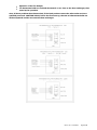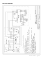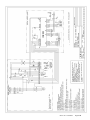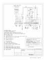
1
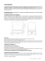
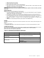
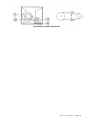
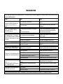
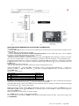
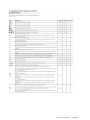
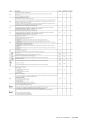
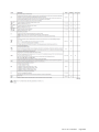
AS COND AS COND EX USE,INSTALLATION AND MAINTENANCE MANUAL fitted with low-NOx modulating pre-mixed gas burners AS COND - AS COND EX WARM AIR HEATERS INDEX INDEX ......................................................................................................................................................................................... 1 COMPOSITION OF THE “AS COND” SERIES HEATER ......................................................................................................... 7 Models from “50” to “65”, with single-phase motor, directly coupled to the fan ........................................................ 7 Models from “80” to “200”, three-phase, with fan’s drive motor .................................................................................. 7 Models from “250” to “300” three-phase, with fan’s drive motor ................................................................................. 8 WEIGHTS and DIMENSIONS "AS COND" SERIES............................................................................................................ 9 COMPOSITION OF THE “AS COND EX” SERIES HEATER ................................................................................................. 10 Models from “50” to “65”, three-phase, with fan’s drive motor .................................................................................. 10 Models from “80” to “200”, three-phase, with fan’s drive motor ................................................................................ 10 Models from “250” to “300”, three-phase, with fan’s drive motor .............................................................................. 11 WEIGHTS and DIMENSIONS "AS COND EX" SERIES .................................................................................................... 12 PLENUM - STANDARD HEAD FOR DIRECT AIR DELIVER ............................................................................................. 13 FILTER BOXES ON AIR INLET DELIVERY – WARM AIR HEATERS OF THE "AS COND" and "EX" SERIES ........... 14 DATA SHEET series: “AS COND” “AS COND EX” .......................................................................................................... 15 INSTALLING THE WARM AIR HEATER AND ITS ACCESSORIES...................................................................................... 16 HEATER LOCATION AND CLEARANCE............................................................................................................................. 16 HEATER LOCATION ............................................................................................................................................................ 16 HEATER DISTANCE FROM WALLS ................................................................................................................................... 16 INSTALLATION ....................................................................................................................................................................... 17 TEMPERATURES ................................................................................................................................................................. 17 BURNER ............................................................................................................................................................................... 17 GAS PIPE.............................................................................................................................................................................. 17 GAS SHUT-OFF AND ALARM DEVICE .............................................................................................................................. 17 ELECTRICAL CONNECTIONS............................................................................................................................................. 17 CONNECTION OF THE FLUE TO THE STACK ................................................................................................................. 18 FLUE/COMBUSTION AIR INTAKE ..................................................................................................................................... 18 TABLE OF PRESSURE DROPS IN CMT PIPES AND ELEMENTS .................................................................................... 20 FLUE AND COMBUSTION AIR INTAKE ELEMENTS ........................................................................................................ 22 CONNECTING THE CONDENSATE DRAIN ....................................................................................................................... 23 ASSEMBLY OF DIRECT AIR DELIVERY PLENUM ............................................................................................................ 24 INSPECTIONS ON FIRST START-UP ...................................................................................................................................... 24 TRI-THERMOSTAT.............................................................................................................................................................. 25 ELECTRICAL DIAGRAMS ........................................................................................................................................................ 27 MAINTENANCE ........................................................................................................................................................................ 30 CLEANING THE HEAT EXCHANGER ................................................................................................................................. 30 TROUBLESHOTING................................................................................................................................................................. 33 ANNEXES ................................................................................................................................................................................. 34 MANUAL “Clima” CAREL for the modulation of burner ................................................................................................. 34 MOST IMPORTANT PARAMETERS TO BE SET BY THE INSTALLER ................................................................................ 38 Rev4. del 17/09/2013 Pagina 1 VERY IMPORTANT NOTICE This manual is an essential and integral part of the warm air heater and must always follow it. The user or the installer must read it carefully, before operating or handling the appliance. The manufacturer may not be held liable for any damage to people, animals and property caused by: improper use of the appliance; unintended use of the appliance; any use of the appliance non compliant with the instructions of this manual; any use non compliant with European, national and regional laws, regulations and standards. The manufacturer will accept no liability in the event that the heater is not installed, periodically checked or serviced by authorised service centres or qualified staff, i.e. “engineers with a specific technical knowledge about heating installations in inhabited buildings”. This appliance may not be used by people (including children) with reduced physical, sensing and mental capabilities or with insufficient experience and knowledge, unless they are monitored or instructed by a person responsible for their safety. This manual is an integral part of the warm air heater, and therefore shall be maintained carefully and must always follow the appliance in the event of a change in ownership. CAUTION! This warm air heater must not be used in explosive atmosphere. The plant project, installation, start-up, periodical inspections and repairs of this warm air heater must be carried out only by skilled personnel. In particular, all obligations provided for by European, national, regional and local laws, regulations, standards and recommendations applicable to design and installation, authorisations, periodical inspections, maintenance, combustion controls and emissions into the atmosphere shall be understood and complied with by the user and the said skilled personnel. In case of troubles and faulty operation of the appliance, the user must disconnect power supply and avoid any attempt of repair, so as not to damage the appliance and/or third parties. See the description in the “Troubleshooting” paragraph of this manual. CAUTION! Before maintenance or servicing, cut-off power supply to the appliance, by selecting turning the master switch to - O-. At the end of the heating season, the user must contact skilled personnel to have the combustion chamber and the heat exchanger cleaned, and (based on the intervals provided for by law) to check the performance of the other components and safety devices, by conducting a combustion test. The results of these operations shall be registered on the "heating plant handbook". The air inlet filter, if any, must be cleaned at appropriate intervals. Remove it from its housing and blow compressed air or wash it (see the "Maintenance" paragraph). The air inlet grille (6), when dirty, must be cleaned by a brush or an air-exhauster, without removing it. Should the appliance be moved to another place, be sure this manual follows it, so that the new user and/or installer can consult it. MEANING OF THE SYMBOLS USED ON THE ELECTRICAL BOARD/CONTROLS Rev4. del 17/09/2013 Pagina 2 GENERAL INFORMATION The warm air heater is fit for the following applications: a) Direct heating of the air conveyed by a ventilating unit The heat exchange occurs by contact between the external walls of the combustion chamber and the air. b) Ventilation only. To use it as according to (a), the heater shall be connected to the power line, the gas piping and a suitable combustion product/condensate drainage system. To use it according to (b), simply connect it to the power line. This warm air heater is to be used to heat the ambient air. This appliance must not be used for other purposes and, in particular, at an average outlet air temperature over 80°C, during normal operation. CAUTION! The manufacturer is liable for the operating characteristics of the heater providing that it is used according to the instructions and subject to the limits described throughout this manual. Warranty If the heater is not installed according to this manual, the warranty will become null and void. STRUCTURAL INSPECTION AND SAFETY REQUIREMENTS The warm air heater is made of an aluminium frame and an external panelling in pre-painted sheet: the panels’ interior is insulated by a glass wool mattress The heating section includes a combustion chamber and a heat exchanger. In this area the insulating mattress is protected from overheating by galvanized steel sheet. The ventilating section, with a centrifugal fan, driven by a single-phase or three-phase belt-drive electric motor, is coupled with the heating section. The ventilating unit is provided with a finger protection grille, that can be removed only by means of a tool. The combustion chamber, made of stainless steel for high temperatures, is bolted to the frame, so that its thermal expansion does not affect its life over the time. The heat exchanger, made of stainless steel pipes, is welded to the combustion chamber. Inspection and maintenance operations may be carried out through large openings on both sides. On the front of the heater you can find: a pre-mixed gas burner (with gas ramp), the modulation kit connected to an air temperature sensor and an electrical control board with: - Master switch - HEATING – BURNER STOP – VENTILATION switch - Voltage signal lamp – Signal lamp for remote switch’s thermal relays – Safety Limit signal lamp; a tri-thermostat consisting of 3 thermostats, which perform the following control and safety functions (located on the top, above the heat exchanger): - FAN (TR): thermostat normally opened, to automatically start and stop the ventilating unit during the "HEATING" phase - LIMIT (TW): normally closed, automatic reset max. temp. thermostat for the burner, which stops the burner automatically, to make sure that the temperature of the air leaving the heater does not exceed the safety limit. - LIMIT2 (STB): normally closed, automatic reset safety thermostat for the burner, which stops the burner automatically, to make sure that the temperature of the air leaving the heater does not exceed the safety limit set by the reference standard. It is calibrated at 100 C° by the manufacturer; these limit must never be modified, to prevent dangerous overheating (to reset the burner, see the instructions on Chapter TRE-THERMOSTAT). Rev4. del 17/09/2013 Pagina 3 OTHER ESSENTIAL SAFETY REQUIREMENTS Electrical equipment. All warm air heaters are checked for conformity as follows: Visual inspection on the electric circuit, and connection tightening Check the grounding continuity Insulation resistance test Voltage test Temperatures. The temperatures of accessible zones, for the manual use of the warm air heater, are in compliance with the reference European standard. Noise. Appropriate measures have been adopted to minimize noise emissions. The relevant values (in db(A)) are listed in the table on table DATA SHEET. Signals. The signals on controls and alarm devices consist of symbols based on ISO7000. These symbols are explained on Chapter MEANING OF THE SYMBOLS. WARM AIR HEATER DATA PLATE A data plate (made with an ultra destructible film, which, once removed, cannot be used again) is affixed on the front of each warm air heater, and shows its technical characteristics. A facsimile of this plate is shown here below. GENERATORE D’ARIA CALDA A CONVEZIONE FORZATA CON BRUCIATORE A GAS PREMISCELATO BASSO NOX CL 5 FORCED CONVECTION WARM AIR HEATER WITH GAS PREMIX BURNER LOW NOX CL 5 GENERATEUR D’AIR CHAUD A CONVECTION FORCEE AVEC BRULEUR GAZ PREMIX LOW NOX CL 5 MOD. TYP. AS COND 65 N° 101001 9121235-2 MESE/ANNO MONTH/YEAR MOIS/ANNEE PORTATA TERMICA NOMINALE NOMINAL HEAT INPUT DEBIT CALORIFIQUE NOMINAL POTENZA TERMICA NOMINALE PUISSANCE CALORIFIQUE UTILE THERMAL RATED POWER RESA TERMICA ALLA Pn kW 73 kW % mc/h 6.100 Pa n° RATED POWER INPUT PUISSANCE ELECTRIQUE ABSOR. TENSIONE - TENSION MADE IN ITALY 76 96,1 PORTATA ARIA AIR DELIVERY DEBIT AIR PRESSIONE STATICA UTILE AVAILABLE AIR PRESSURE PRESSION AIR DISPONIBLE POTENZA ELETTRICA ASSORBITA PAESE DESTINAZIONE COUNTRY OF DESTINATION PAYS DE DESTINATION 02-2010 1x 0,736 kW 230/1F/50HZ IT CATEGORIA CATEGORY CATEGORIE II2H3B/P PIN 0694BU1913 GRADO DI PROTEZIONE PROTECTION LEVEL IP X5D PROTECTION DEGREE CONFIG. TIPO CONFIG. TYPE CONFIG. TYPE B23, C13, C33, C53 Rev4. del 17/09/2013 Pagina 4 PACKAGING The warm air heater is delivered on a pallet, and is protected by a pluribol film. The air inlet plenum, if installed, is packaged together with heater or separately, according to the models. TRANSPORT, LOADING AND UNLOADING Transport, loading and unloading must be carried out carefully, to prevent damage to the appliance, as well as to people, animals and property. To load and unload the appliance, use a lift truck of suitable capacity, according to the safety factor (see the gross weight of the appliance in the table on Chapter WEIGHT AND DIMENSIONS). During these operations, the centre of gravity of the appliance must remain in the middle, without dangerous inclinations. After removing the packaging, check the condition of the appliance. If in doubt, contact the manufacturer or its agent. The heater is a compact appliance, with its electrical board and the burner. PACKAGING MATERIALS Packaging materials (wood, cardboard, polystyrene, nails etc.) shall be collected and disposed of according to the laws in force. CAUTION! Don't leave these materials within the reach of children, because they may be a source of danger. Generator series "AS COND EX" packaged POSITIONING After removing its packaging, the heater must be positioned as described on page 17. CAUTION! Don't turn the heater upside-down INSPECTIONS BEFORE START-UP The heater is equipped with an electrical board, which comprises: A master switch A HEATING – BURNER STOP – VENTILATION switch A terminal board Thee signal lamps on the board’s door indicate: 1. VOLTAGE: the board is powered 2. THERMAL RELAYS ON: the remote switch’s thermal relays have de-energized the fan. From mod. “X80” to mod. “X300” only. 3. LIMIT2 ENABLED:: the safety Limit has de-energized the burner. Check that: the electrical board is properly connected to the single-phase power line (for models “50” and “65”; three-phase from mod. “80” to mod. “300”) and that the main power cable has a suitable section for Ampere absorption the rotation direction of the fan(s) is the one shown on the impeller (figure 13) the calibration of the remote switch’s thermal relays is correct (from mod. “80” to mod. “300”): the relevant values (In Amperes) are shown on Chapter DATA SHEET. there are no obstacles on the delivery and on the recovery nozzle, which could obstruct air circulation the fins of the air delivery nozzles, if any, are not too inclined, so as not to reduce their capacity the air inlet filters are clean, not to reduce the air capacity. Rev4. del 17/09/2013 Pagina 5 OTHER INSPECTIONS IN THE HEATING PHASE Check that: 1. The fuel supply pipe to the burner is compliant with the Standards in force. Ask the piping installer to issue the certificate of the gas supply system, as well as the final test certificate 2. The burner is supplied with the type of gas for which it has been designed 3. The calibration of the FAN, LIMIT and LIMIT2 thermostats is correct (see Chapter TRETHERMOSTAT 4. The flue system is compliant (see the provisions/regulations applicable to flues), as well as the combustion air piping, if any 5. The environment ensures enough ventilation and combustion air, according to the standards in force. 6. The condensate disposal piping it has been installed according to the norms (see Chapter CONNECTING THE CONDENSATE DRAIN Note. Carefully read the manual of the burner supplied by the manufacturer OPERATION DESCRIPTION Heating phase. The master switch on the electrical board must be in the -1- position, and the change-over switch in the -HEATING- position. Whenever the room thermostat requires heating, the burner begins its self-test and pre-wash cycle, which is followed by combustion. Within approximately 5 minutes from the beginning of the combustion, the FAN thermostat starts the ventilating unit automatically. When the burner is turned off by the room thermostat, the ventilating unit remains on in order to cool the heat exchanger, and is turned off automatically by the FAN, to prevent cold air supply. The burner can be stopped also by the LIMIT (the burner’s max. temp. thermostat), calibrated at 80°C, if the temperature of the air leaving the heater exceeds this temperature limit. The LIMIT resets the burner automatically, once the air has cooled. The burner can be stopped also by the LIMIT2 (the burner’s safety thermostat), calibrated at 100°C, if the temperature of the air leaving the heater exceeds the safety limit set by the applicable standard. To reset the burner, let the air cool down and then proceed as specified on chapter TRI-THERMOSTAT of this manual. CAUTION! The LIMIT2 activation detects an operational fault; please contact an authorised aftersale service or qualified technical personnel. STOP If the switch is moved to the -BURNER STOP- position, the burner stops, while the ventilating units continues to turn, up until it is turned off by the FAN thermostat (on completion of the cooling phase). to de-energize the heater, move the master switch (IG) to position -O-. CAUTION! Before disconnecting power supply (with the master switch), make sure that the heater has cooled down; otherwise the appliance life could be shorter. Ventilation phase. Turn the switch to the -VENTILATION- position: the heater will work as fan only, and the burner will be cut off. CAUTION! Never turn off the heater using the master switch; use its own switch, the room thermostat or the clock, if installed: otherwise, the heat exchanger is likely to be still heated and could be strained. MODULATION REGULATOR CAREL TYPE CLIMA ( read his instructions supplied with the heater) The burner, of modulating type, is controlled (during flame modulation phases) by the ambient terminal device type “Clima”, supplied with the heater, with an air sensor NTC in it. The “Clima” is to be installed in the room to be heated. To set the ambient temperature for the modulation read here down: OUTSIDE TEMPERATURE’S PROBE -Press increase to Option on request Rev4. del 17/09/2013 Pagina 6 The “Clima” device operates on the burner as modulation control, room thermostat, clock thermostat. For example: when we set 20˚C, the modulating starts on at 18˚C and the burner will be turned off just when it will reach 20˚C. The burner will start anew at 19,5°C. The regulator CLIMA is powered with 24V, so the electric board contains the transformer of 230V-24V. The regulator send a signal of 010V for flame modulation. The communication cable 0-10V between Clima and burner could have the max distance of 10 m with section 0,5 mm2, or just max 30 mt with concealed cable with section 1,5 mm2. COMPOSITION OF THE “AS COND” SERIES HEATER, Models from “50” to “65”, with single-phase motor, directly coupled to the fan 1) Air outlet 2) Fume box door 3) Burner 4) Burner anchor plate 5) Centrifugal fan 6) Air inlet grille 7) Condensate drain 8) Stack connection 9) Rear fume box 9.1) Front fume box 10) Heat exchanger 11) Combustion chamber 12) Fan motor 13) Fan-Limit-Limit2 14) Electrical board 15) Air baffles 16) Frame made of aluminium sections 17) External insulated panels. Models from “80” to “200”, three-phase, with fan’s drive motor 1) Air outlet 2) Fume box door 3) Burner 4) Burner anchor plate 5) Centrifugal fan 6) Air inlet grille 7) Condensate drain 8) Stack connection 9) Rear fume box 9.1) Front fume box 10) Heat exchanger 11) Combustion chamber 12) Fan motor 13) Fan-Limit-Limit2 14) Electrical board 15) Air baffles 16) Frame made of aluminium sections 17) External insulated panels 18) Motor's belt tightening slide 19) Pulleys and drive belts Note: for 80/100 the burner has a protection (see item 15 mod. 50/65) Rev4. del 17/09/2013 Pagina 7 Models from “250” to “300” three-phase, with fan’s drive motor 1) Air outlet 2) Fume box door 3) Burner 4) Burner anchor plate 5) Centrifugal fan 6) Air inlet grille 7) Condensate drain 8) Stack connection 9) Rear fume box 9.1) Front fume box 10) Heat exchanger 11) Combustion chamber 12) Fan motor 13) Fan-Limit-Limit2 14) Electrical board 15) Air baffles 16) Frame made of aluminium sections 17) External insulated panels 18) Motor's belt tightening slide 19) Pulleys and drive belts Fig 1 Warm air heater 1Ph with air recovery duct and head-heater and warm air heater 3Ph with heatd-heater. Rev4. del 17/09/2013 Pagina 8 WEIGHTS and DIMENSIONS "ASCOND" SERIES Weight in [kg] and dimensions in [mm]. Head-Heater connection Connection of the air delivery duct Connection of the air delivery duct The air inlet grille is on the left till Mod. 200, On the right till Mod.250 onward The grille position can be reversed. HEATER MOD. 50 65 80 100 150 175 200 250 300 Lenght Width Height Head height Flue height A 870 870 1020 1020 1440 1440 1440 1790 1790 B 636 636 750 750 1020 1020 1020 1020 1020 C 1750 1750 1950 1950 2340 2340 2340 2340 2340 D 305 305 405 405 405 405 405 405 405 E 860 860 935 935 1070 1070 1070 1130 1130 Air Outlet-Inlet connection F 596 596 670 670 940 940 940 940 940 G 830 830 940 940 1360 1360 1360 1710 1710 Air Inlet connection H 630 630 690 690 760 760 760 760 760 I 830 830 940 940 1360 1360 1360 1710 1710 Frame profile Flue system L 20 20 40 40 40 40 40 40 40 Ø 100 100 130 130 150 150 150 200 200 Weight (1) net Kg 165 170 270 275 435 440 445 570 580 packed Kg 175 180 282 287 450 455 460 590 600 1) complete with burner and gas ramp Rev4. del 17/09/2013 Pagina 9 Net head weight Kg 17 17 27 27 42 42 42 50 50 COMPOSITION OF THE “AS COND EX” SERIES HEATER Models from “50” to “65”, three-phase, with fan’s drive motor 1) Air outlet 2) Fume box door 3) Burner 4) Burner anchor plate 5) Centrifugal fan 6) Air inlet grille 7) Condensate drain 8) Stack connection 9) Rear fume box 9.1) Front fume box 10) Heat exchanger 11) Combustion chamber 12) Fan motor 13) Fan-Limit-Limit2 14) Electrical board 15) Air baffles 16) Frame made of aluminium sections 17) External insulated panels. 20) Booth protecting burner and electric components Models from “80” to “200”, three-phase, with fan’s drive motor 1) Air outlet 2) Fume box door 3) Burner 4) Burner anchor plate 5) Centrifugal fan 6) Air inlet grille 7) Condensate drain 8) Stack connection 9) Rear fume box 9.1) Front fume box 10) Heat exchanger 11) Combustion chamber 12) Fan motor 13) Fan-Limit-Limit2 14) Electrical board 15) Air baffles 16) Frame made of aluminium sections 17) External insulated panels 18) Motor's belt tightening slide 19) Pulleys and drive belts 20) Booth protecting burner and electric components Rev4. del 17/09/2013 Pagina 10 Models from “250” to “300”, three-phase, with fan’s drive motor 1) Air outlet 2) Fume box door 3) Burner 4) Burner anchor plate 5) Centrifugal fan 6) Air inlet grille 7) Condensate drain 8) Stack connection 9) Rear fume box 9.1) Front fume box 10) Heat exchanger 11) Combustion chamber 12) Fan motor 13) Fan-Limit-Limit2 14) Electrical board 15) Air baffles 16) Frame made of aluminium sections 17) External insulated panels 18) Motor's belt tightening slide 19) Pulleys and drive belts 20) Booth protecting burner and electric components Rev4. del 17/09/2013 Pagina 11 WEIGHTS and DIMENSIONS "AS COND EX" SERIES Weight on [kg] and dimensions on [mm]. Head-Heater connection Connection of the air recovery duct The air inlet grille is on the left till Mod. 200, On the right till Mod.250 onward The grille position can be reversed. Length Width Height Flue exhaust connection A B C E F G H 50 870 636 1750 860 596 830 65 870 636 1750 860 596 830 80 1020 750 1950 935 670 100 1020 750 1950 935 150 1440 1020 2340 175 1440 1020 200 1440 250 300 HEATER MOD. 1) Air delivery connection Air inlet connection Burner cabin Heater weight Depth Height Flue exhaust net packed I N O Ø Kg Kg 630 830 400 1100 100 187 197 630 830 400 1100 100 192 202 940 690 940 400 1220 130 295 307 670 940 690 940 400 1220 130 300 312 1070 940 1360 760 1360 650 1540 150 479 494 2340 1070 940 1360 760 1360 650 1540 150 484 499 1020 2340 1070 940 1360 760 1360 650 1540 150 489 504 1790 1020 2340 1130 940 1710 760 1710 800 2170 200 615 635 1790 1020 2340 1130 940 1710 760 1710 800 2170 200 625 645 complete with burner and gas ramp Rev4. del 17/09/2013 Pagina 12 PLENUM - STANDARD HEAD FOR DIRECT AIR DELIVER WARM AIR HEATERS OF THE "AS COND" SERIES Air blown by the nozzles on three sides, and dimensions in mm MOD. P Q D R T S No. of nozzles 1) Air blown in m. max 2) min 50 825 591 305 300 300 200 1+1+1 16 16 65 825 591 305 300 300 200 1+1+1 16 16 80 935 665 405 550 550 300 1+1+1 34 34 100 935 665 405 550 550 300 1+1+1 38 38 150 1355 935 405 750 750 300 1+1+1 55 55 175 1355 935 405 750 750 300 1+1+1 60 60 200 1355 935 405 750 750 300 1+1+1 63 63 250 1355 935 405 750 750 300 1+2+1 74 60 300 1355 935 405 750 750 300 1+2+1 80 62 1) Short side (Q) + long side (P) + short side (Q). 2) The final speed of the blown air is 0.15 m/sec, and the nozzle fins’ deflection is 0°. If deflection = 30°, multiply the blown air value by 0.65. Note: T x S / R x S = DIMENSIONS OF A SINGLE NOZZLE Rev4. del 17/09/2013 Pagina 13 FILTER BOXES ON AIR INLET DELIVERY – WARM AIR HEATERS OF THE "AS COND" and "AS COND EX" SERIES Filters’ pressure drops and dimensions in mm MOD. 50 U V Z Y X 870 620 60 830 580 1x810x640x48 70 2x400x500x48 106 870 620 60 830 580 1x810x640x48 93 2x500x400x48 105 980 680 60 940 630 1x910x695x48 1x625x500x48 1x625x400x48 1x910x695x48 97 113 1x625x500x48 1x625x400x48 145 4x625x400x98 109 2x625x500x98 1x625x400x98 80 4x625x400x98 141 2x625x500x98 1x625x400x98 103 4x625x400x98 165 2x625x500x98 1x625x400x98 121 50 EX 65 65 EX 80 80 EX 100 980 680 60 940 630 100 EX 150 1440 840 200 1400 800 150 EX 175 1440 840 200 1400 800 175 EX 200 1440 840 200 1400 800 200 EX Filters (1) Pressure drop [Pa] (2) 125 250 1790 840 200 1750 800 2x625x400x98 4x500x400x98 141 300 1790 840 200 1750 800 2x625x400x98 4x500x400x98 170 1) Efficiency ASHRAE52/76 DUST WEIGHT: 87% 2) Pressure drop of a new filter. CAUTION! For plant calculations, this pressure drop for rather dirty (but not clogged) filters must be increased by at least 50%, and must be subtracted from the useful head of the heater. Rev4. del 17/09/2013 Pagina 14 DATA SHEET series: “AS COND” “AS COND EX” THERMAL PERFORMANCE Mod. 50 65 80 100 150 175 200 250 300 Rated heat input Qn kW 61,1 76 98,5 122 179 203 238 270 313 Rated heat rating Pn kW 59,8 73,0 96,3 116,6 178,6 201,8 234,2 269 310 Thermal efficiency at rated thermal power Pn % 97,9 96,1 97,8 95,6 99,8 99,4 98,4 99,3 98,7 Heat input at 50% of the rated heat input kW 30,55 38 49,25 61 89,5 101,5 119 162 187,8 kW 31,8 39,0 51,6 62,1 93,8 106,0 123,6 167,3 191,3 % 104,2 102,6 104,9 101,8 104,8 104,5 103,9 103,3 101,8 Heat rating at 50% of the rated heat input Thermal efficiency at 50% of the rated heat input Minimum heat input Qmin kW 22 22 31 31 53 53 53 88 102 Heat rating at Qmin kW 23,3 23,3 33,4 33,4 56,65 56,65 56,65 94,51 109 Thermal efficiency at minimum heat input Qmin % 106 106 107,8 107,8 106,9 106,9 106,9 107,4 106,9 mbar 4,3 7,5 3,4 5,1 3,9 5,2 6,2 4 4,8 mbar 4 7,4 3,1 4,7 3,7 5 5,9 3,8 4,6 l/h 2,15 2,15 4,06 4,06 4,5 4,5 4,5 5,52 5,2 Air flow rate at 18 °C mc/h 4700 6100 7560 9200 13000 15800 18000 20800 24000 Useful static pressure Pa 150 150 150 150 200 200 200 200 200 DELTA T AIR at PN °C °C 37,4 35,1 37,2 37,2 40,4 37,6 38,3 37,1 37 8,04 10,42 12,91 18,94 21,48 25,19 28,57 33,12 Backpressure in the combustion chamber, with G20 at Qn Backpressure in the combustion chamber, with G30 at Qn Condensate produced when the room temperature is 20°C AERAULIC PERFORMANCE MAX GAS CONSUMPTION AT 15°C-1013 mba METHANE G20 at 20 mbar mc/h 6,47 NAT. GAS G25 at 25 mbar mc/h 7,52 9,4 12,1 15,0 22,0 25,0 29,3 33,24 38,53 PROPANE G31 at 37 mbar Kg/h 4,75 5,90 7,65 9,48 13,91 15,77 18,49 20,98 24,32 BUTANE G30 at 28 mbar Kg/h 4,82 5,99 7,77 9,62 14,12 16,01 18,77 21,29 24,68 CO2 at Qn with G20 (tolerance ± 0.2) % 8,7 8,9 8,9 8,9 8,8 8,7 8,7 8,3 8,3 CO2 at Qn with G31 (tolerance ± 0.2) % 10,5 10,5 10,5 10,5 10,5 10,5 10,5 10 10 NOx ( ≤50 Mg/kWh ) CL 4 5,5 3x2 4x2 Classe 5 ELECTRICAL DATA Fan motor capacity KW x n. Fan motor supply voltage V-Ph-Hz Fan motor absorption A Fan motor absorption/voltage 3F230V 50Hz A Sound pressure ( at 5 m ) Protection degree of “XE” “XEO” “XR” versions 0,736 0,736 1,5 2,2 230 V - 1 - 50 7,7 7,7 3 400 V - 3+N - 50 3,6 5,1 7 9,2 12 7x2 9,2 x 2 6,2 9,3 12 15 20 12 x 2 15 x 2 dB(A) 70 72 72 73 71 73 74 74 75 IP X5D X5D X5D X5D X5D X5D X5D X5D X5D 2,2 3 4 5,5 7,5 3x2 5,5 x 2 ELECTRICAL DATA, WITH USEFUL PRESSURE = 300 Pa Fan motor capacity Fan motor supply voltage Fan motor absorption/voltage 3F400V 50Hz Fan motor absorption/voltage 3F230V 50Hz kW 1,1 1,5 V-Ph-Hz 400 V - 3+N - 50 A 2,9 3,6 5,1 7 9,2 12 17,8 7x2 9,2 x 2 A 4,8 6,2 9,3 12 15 20 31 12 x 2 15 x 2 Flue connection/combustion air intake Ǿ GAS CATEGORY IT II 2H3B/P tipo B23 – C13 – C33 – C53 Type of appliance, based on exhaust devices/combustion air intake Warm air heaters can be used together with RIELLO burner RIELLO 100/100 RX80 S/PV RX80 S/PV 130/130 RX100S/ PV 150/150 RX120 S/PV RX250 S/PV RX250 S/PV 200/200 RX250 S/PV Rev4. del 17/09/2013 RX350 S/P Pagina 15 RX350 S/P INSTALLING THE WARM AIR HEATER AND ITS ACCESSORIES IMPORTANT! This part of the manual is intended for the installer or qualified personnel. HEATER LOCATION AND CLEARANCE The warm air heater must be installed according to the provisions of the Ministerial Decree dated 12 April 1996 and of other regulations and standards, as applicable, of which the installer must be aware. Ventilate the room where the warm air heater is installed according to the provisions of the laws, regulations and standards referenced above. Try to cover all the heated area with the blown air In the presence of considerable air infiltration (e.g. from doors), adjust the air flow Do not direct the air flows against obstacles, such as pillars and stored material If the room is provided with air extractors, install the warn air heater on the opposite wall, as well as an outside air intake, in order to supply new air. HEATER LOCATION Leave an appropriate clearance around the heater, free of combustible material, and calculate the distance in compliance with the M.D. dated 12 April 1996. HEATER DISTANCE FROM WALLS To calculate the minimum distance of the heater from walls and ceiling, refer to the M.D. dated 12 April 1996 and other regulations in force. The minimum distances recommended by the manufacturer for maintenance of heater, burner and accessories, if any, are indicated below. MOD. A [mm] B (1) [mm] C [mm] 50 1000 700 300 65 1000 700 300 80 1000 820 300 100 1000 820 300 150 1300 820 600 175 1300 820 600 200 1300 820 600 250 1300 820 600 300 1300 820 600 Check this height based on the possibility of disassembling and servicing the flue system. Fig 4 Minimum distance of the heater from walls and ceiling scheme Rev4. del 17/09/2013 Pagina 16 INSTALLATION The warm air heater must be installed by skilled personnel, qualified pursuant to law. The warm air heater must be installed according to national and local regulations. TEMPERATURES The operating temperatures of burner and electric components are: minimum 0°C; maximum 60°C. In the case of “EX” versions installed outdoor, at operating temperatures below 0°C, CMT recommends an antifrost kit, mounted in the burner booth on demand. This kit maintains the temperature inside the burner booth at 0°C when the outdoor temperature drops below this limit. BURNER The warm air heater is supplied together with a modulating pre-mixed gas burner (series RX), complete with gas ramp, modulating kit and modulating air sensor: all these elements can form a complete heating unit. The burner is assembled, wired to the warm air heater and the tri-thermostat, adjusted and tested. Anyway, during the first start-up and periodical inspections, check that combustion parameters are the ones shown in the technical data table on Chapter DATA SHEET. If the appliance has to be re-adjusted (for example if the burner is replaced), this operation must be performed by a qualified engineer, according to the instructions provided in the RX burner manual, delivered together with the heater. NOTE: the CO value should range between 0 and 20 ppm ! GAS PIPE The gas pipe must be manufactured to reference UNI-CIG or Country standards. Pipe diameters must be calculated according to the heater capacity and distance from the meter, and sized so that the total pressure drop between the meter and any heater does not exceed 1 mbar (methane) and 2 mbar (LPG). The reference UNI-CIG standards illustrate the diameter tables, based on capacity and length. Install a valve and a gas filter near the heater. For methane, make sure that the meter can deliver the gas volume required. For propane, install a two-stage pressure reducing system: install a first stage reducer close to the tank (calibrated at 1.5 bar) and a second stage reducer before the internal piping. GAS SHUT-OFF AND ALARM DEVICE The warm air heater must be provided with a gas shut-off and alarm device to detect any gas leak, in compliance with national/local laws and regulations in force. ELECTRICAL CONNECTIONS (see wiring diagrams on chapter ELECTRIC DIAGRAM) Electrical connections must comply with national and local regulations and standards (IEE standards included). This heater is delivered complete with all electrical connections, except for connection to power supply and remote control or room thermostat, to be carried out by the installer, based on the wiring diagram on Chapter ELECTRIC DIAGRAM of this manual. Do not de-energize the heater using the master switch. During installation, make sure the heater is isolated from the mains supply, by means of a dedicated omnipolar switch (min. space for contact opening: 3 mm), installed upstream of the heater, of suitable size, based on the heater's total electric load and in compliance with current standards. The main power cables must be of suitable size and T marked. The ground cable must be longer than the others (by approx. 2 cm). The heater’s supply voltage must be 1F 230Vac (50 and 65) and 3F 400V+N 50Hz (80 to 200). The heater must be grounded according to the standards in force. Connect the fire damper (if installed) to the heater’s electrical board. When installing the room thermostat: - Install it in a room heated by the warm air heater. Do not leave it under direct sunlight. Do not install it on a cold wall, but rather on an internal wall. Do not install it in a place directly blown by the air jet. Rev4. del 17/09/2013 Pagina 17 ! CAUTION! Do not connect the timer, if installed, in series with the mains supply; connect it to the room thermostat’s line. Otherwise, the timer would turn off the heater, and all the unused heat would remain in the appliance (which could be damaged) CONNECTION OF THE FLUE TO THE STACK If requested by local regulations, or when other options are selected, the warm air heater must be connected to a stack of proper sized, made of suitable materials and installed according to national and local environmental regulations and standards. The diameter of the pipe connecting the heater to the stack must be equal to or larger than the flue; all joints must be sealed. When dimensioning the ducts/stack system, please remember that the maximum pressure drop must not exceed 50 Pa. FLUE/COMBUSTION AIR INTAKE The warm air heaters of the X series are fit for the following flue/combustion air intake systems: B23 and of tight type, C13, C33, C53, C63. Please consult national and local regulations and standards, to make sure that the desired system can be installed. Comply with the installation diagrams provided throughout this manual. The sum of maximum pressure drops between the flue and the combustion air intake ( if installed), including terminals, must not exceed 50 Pa. For more information about duct joints, please contact A2B Accorroni directly or your supplier. The table on the next page shows the pressure drops in the pipes, flue/combustion air intake for a variety of models and diameters, supplied by A2B Accorroni. These pipes and elements are made of smooth stainless steel. A2B Accorroni warrants the heater performance if its own pipes and elements are mounted (as specified in the table FLUE AND COMBUSTION AIR INTAKE ELEMENTS). The installer can use pipes and elements manufactured by other companies, providing that pressure drops do not exceed the ones shown in the table PRESSURE DROPS IN PIPES AND ELEMENTS. Rev4. del 17/09/2013 Pagina 18 Rev4. del 17/09/2013 Pagina 19 TABLE OF PRESSURE DROPS IN CMT PIPES AND ELEMENTS (FOR FLUE AND COMBUSTION AIR INTAKE) MODEL 50 65 80 100 150 175 200 50 50 50 50 50 50 50 2,7 4 6,5 9,8 - - - 2 3 4,8 7,2 - - - Flue 0,8 1,1 1,8 2,7 5,4 6,2 9,1 Combustion air intake 0,6 0,8 1,3 1,9 4,0 7,5 6,7 Flue 0,4 0,6 1,0 1,5 2,9 3,0 4,9 Combustion air intake 0,3 0,4 0,7 1,0 1,9 2,0 3,3 Flue 5,4 8,0 13,0 19,6 - - - Combustion air intake 4,0 6,0 9,6 14,4 - - - Flue 1,5 2,2 3,6 5,4 10,8 12,4 18,2 Combustion air intake 1,1 1,6 2,6 3,9 8,0 15,0 13,4 Flue - 1,2 2,0 3,0 5,8 6,0 9,8 Combustion air intake - 0,8 1,3 1,9 3,9 4,0 6,6 Flue 2,7 4,0 6,5 9,8 - - - Combustion air intake 2,0 3,0 4,8 7,2 - - - Flue 0,8 1,1 1,8 2,7 5,4 6,2 9,1 Combustion air intake 0,6 0,8 1,3 1,9 4,0 7,5 6,7 Flue - 0,6 1,0 1,5 2,9 3,0 4,9 Combustion air intake - 0,4 0,7 1,0 1,9 2,0 3,3 “Chinese hat” terminal Ø 100 3,8 5,6 9,1 13,7 - - - “Chinese hat” terminal Ø 130 1,1 1,6 2,5 3,8 7,6 8,7 12,7 “Chinese hat” terminal Ø 150 0,6 0,9 1,4 2,1 4,1 4,2 6,9 Weatherproof terminal Ø 100 4,7 7,0 11,4 17,2 - - - Weatherproof terminal Ø 130 1,3 2,0 3,2 4,7 9,5 10,9 15,9 Weatherproof terminal Ø 150 0,7 1,1 1,8 2,6 5,1 5,3 8,6 TE90° union - Ø 100 8,1 12,0 19,5 29,4 - - - TE90° union - Ø 130 2,3 3,4 5,4 8,1 16,2 18,6 27,3 TE90° union - Ø 150 1,26 1,83 3 4,5 8,7 9 14,7 Flue 2,7 4,0 6,5 9,8 - - - Combustion air intake 2,0 3,0 4,8 7,2 - - - Flue 0,8 1,1 1,8 2,7 5,4 6,2 9,1 Combustion air intake 0,6 0,8 1,3 1,9 4,0 7,5 6,7 Flue - 0,6 1,0 1,5 2,9 3,0 4,9 Combustion air intake - 0,4 0,7 1,0 1,9 2,0 3,3 Available pressure (Pa) for flue and combustion air intake PIPE DESCRIPTION Rigid pipe Ø 100 mm -Length 1 m Rigid pipe Ø 130 mm -Length 1 m Rigid pipe Ø 150 mm -Length 1 m Flue Combustion air intake ELEMENT DESCRIPTION 90° moulded bend R/D=1.5 - Ø 100 mm 90° moulded bend R/D=1.5 - Ø 130 mm 90° moulded bend R/D=1.5 - Ø 150 mm 45° moulded bend R/D=1.5 - Ø 100 mm 45° moulded bend R/D=1.5 - Ø 130 mm 45° moulded bend R/D=1.5 - Ø 150 mm TR terminal - Ø 100 mm TR terminal - Ø 130 mm TR terminal - Ø 150 mm Rev4. del 17/09/2013 Pagina 20 MODEL Available pressure (Pa) for flue and combustion air intake Rigid pipe Ø 250 mm -Length 1 m Rigid pipe Ø 300 mm -Length 1 m 300 50 50 Pressure drop in CMT pipe for length unit Pa/m PIPE DESCRIPTION Rigid pipe Ø 200 mm -Length 1 m 250 Flue Combustion air intake Flue Combustion air intake Flue Combustion air intake 2,5 3,4 1,7 2,3 - - - - - - - Pressure drop Pa/element ELEMENT DESCRIPTION 5,0 6,8 3,4 4,6 - - - - - - -- - 2,5 3,4 1,7 2,3 “Chinese hat” terminal Ø 200 3,5 4,8 “Chinese hat” terminal Ø 250 - - “Chinese hat” terminal Ø 300 - - Weatherproof terminal Ø 200 2,9 3,9 Weatherproof terminal Ø 250 - - Weatherproof terminal Ø 300 - - TE90° union - Ø 200 3,8 5,1 TE90° union - Ø 250 - - TE90° union - Ø 300 - - 2,5 3,4 1,9 2,5 - - - - - - - - 90° moulded bend R/D=1.5 - Ø 200 mm 90° moulded bend R/D=1.5 - Ø 250 mm 90° moulded bend R/D=1.5 - Ø 300 mm 45° moulded bend R/D=1.5 - Ø 200 mm 45° moulded bend R/D=1.5 - Ø 250 mm 45° moulded bend R/D=1.5 - Ø 300 mm TR terminal - Ø 200 mm TR terminal - Ø 250 mm TR terminal - Ø 300 mm Flue Combustion air intake Flue Combustion air intake Flue Combustion air intake Flue Combustion air intake Flue Combustion air intake Flue Combustion air intake Flue Combustion air intake Flue Combustion air intake Flue Combustion air intake Rev4. del 17/09/2013 Pagina 21 FLUE AND COMBUSTION AIR INTAKE ELEMENTS DESCRIPTION ELEMENT DIMENSIONS D1 100 130 150 200 D3 240 320 320 400 D3 240 320 320 400 A B 185 205 210 225 240 240 185 135 90° T UNION HU 275 275 445 440 45° MOULDED BEND A B 92 213 90 235 95 245 140 310 5/30° ADJUSTABLE FLASHING (“T7”) B 110 140 160 210 WINDPROOF WALL TERMINAL (“TR”) A B 120 150 160 150 170 150 220 150 “T6” CHINESE HAT” “T20” WEATHERPROOF TERMINAL 90° MOULDED BEND Rev4. del 17/09/2013 Pagina 22 CONNECTING THE CONDENSATE DRAIN The warm air heater is provided with a condensate drain pipe, flue side, which drains the condensate produced in the heat exchanger. The sloping tubes of the heat exchanger let the condensate flow towards the rear fume box and the condensate drain. A trap is also supplied, and the installer shall connect it to the heater’s condensate drain pipe and to the condensate disposal system (see the drawing below). Unions must be watertight. The disposal system piping must be calculated based on the condensate litres/hour (see the table on Chapter DATA SHEET), and its internal diameter must not be less than 20 mm. The condensate disposal pipes must be made of synthetic material (such as PVC or corrosion-proof stainless steel). Do not use galvanized steel pipes. The trap provided is complete with a float valve, to prevent fume leaks, and must be filled with water before the first start-up. The condensate disposal piping can be: - provided with trap and closed disposal pipe. Use this system for warm air heaters installed in the heated ambient or inside a room. Due to frost hazard, install an open piping (see the drawing below) for outdoor disposal systems. Caution: the condensate disposal piping must be installed at a level lower than the trap. - free: this system is recommended for outdoor warm air heaters, if permitted by local regulations. The condensate is drained directly outside. Caution! To let the condensate out, make sure the warm air heater has been installed on a flat surface. Caution! The pH of the condensate produce during methane combustion is approx. 3.5! This pH can be neutralised by a condensate neutralisation kit. Fig 5 Trap with closed piping and trap with open piping Rev4. del 17/09/2013 Pagina 23 ASSEMBLY OF DIRECT AIR DELIVERY PLENUM The plenum, if any, must be assembled as described on chapter PLENUM of this manual; it is recommended to apply silicone sealant on contact surfaces. In the standard version, the plenum is provided with grilles on three sides and adjustable horizontal/vertical fins. CAUTION! Make sure the air delivery fins are not too inclined, for their capacity and delivery would be reduced. INSPECTIONS ON FIRST START-UP Check the performance of burner RX and make sure that the emissions of CO2, CO and Nox do not exceed the pre-determined tolerances, as shown in the table on Chapter DATA SHEET. Consul the manual of the RX burner, delivered together with this warm air heater. Visually check that the burner flame is regular and does not hit the bottom of the combustion chamber. Check that the direction of rotation of the fan(s) is the one indicated by the arrow on the impeller (see fig. 7) Check motor absorption by means of ammeter and make sure it does not exceed the values specified on Chapter DATA SHEET. Check the performance of heater thermostats: FAN, LIMIT and LIMIT2 (see Chapter TRITHERMOSTAT) Perform a combustion analysis Prepare a power station or plant handbook and record the information required to be disclosed pursuant to the laws, rules, regulations and standards in force. Fig 6 Electrical board for 1Ph and 3Ph. Fig 7 Direction of rotation of the fan(s) Rev4. del 17/09/2013 Pagina 24 TRI-THERMOSTAT Three thermostats composed of a FAN, LIMIT2 and LIMIT FAN (TR)- fan thermostat, normally open, to automatic start and stop the fan when the average air outlet temperature reaches a pre-set value. The set point is fixed by moving the setpoint marker (2) in an internal scale (3), placed inside the TR casing. This adjustment must be set to 30°C. Setting this value over, a delay on fan starting may be caused, so increasing fuel consumption and impairing the long life of the heater. On the cooling phase, the thermostat stops the fan at about 14°C, lower his starting point. o For all installations, EXCEPT for installations such as PRESSOSTATIC structure, the fan is operated as described in paragraph FAN (TR). o For application in PRESSOSTATIC STRUCTURE the FAN must operate continuously. The electrical connections of the thermostat are performed in order to keep the fan always on (see scheme below). LIMIT2 (STB)- Security limit thermostat for the burner, normally closed with manual reset, to automatic stop the burner in case the average air outlet temperature overheat above the preset value. The set point at 100°C, is fixed by the manufacturer. This set point must not be changed. The LIMIT2, when intervening , stops the burner, while the fan keeps turning to cool the heat exchanger. To reset the burner, first wait the air outlet temperature drops down; than push the reset green button . LIMIT (TW)- Temperature limit thermostat for the burner, normally closed , to automatic stop the burner when the average air outlet temperature exceeds the pre-set value. The set point, fixed by the manufacturer inside the casing, is at 70°C; and can be increased maximum at 80°C. The LIMIT reset is automatic, when air outlet temperature drops of about 14°C, below his set point. CAUTION! Make sure that the manual-reset LIMIT2 is not activated due to: Low air flow rate, caused by obstructions and obstacles in the air exhaust/distribution system Clogged air filters (if installed) Heater stopped using the master switch or owing to a power failure during operation Rev4. del 17/09/2013 Pagina 25 Operation of the fire damper Tri-thermostat bulbs too inclined downwards or too close to the heat exchanger, that speed up its operation. Once all these problems have been solved, if the fault persists contact the after-sales service or qualified personnel. CAUTION! Check, before the first start-up, that the tri-thermostat bulbs are inclined upwards and do not touch the heat exchanger. Rev4. del 17/09/2013 Pagina 26 ELECTRICAL DIAGRAMS Rev4. del 17/09/2013 Pagina 27 Rev4. del 17/09/2013 Pagina 28 Rev4. del 17/09/2013 Pagina 29 MAINTENANCE The warm air heater and the burner must be serviced by an authorised service centre or by qualified personnel, in compliance with the requirements set forth by law. For proper and safe warm air heater operation, and for its long life, the operations listed below should be carried out at regular intervals: CAUTION! Before doing maintenance or servicing the appliance, disconnect it from mains supply and close fuel supply. CLEANING THE HEAT EXCHANGER the heat exchanger must be cleaned from soot and deposits, to preserve heat exchange capacity. Clean it at the end of each heating season or more often. Start-up defects could be due to the presence of soot inside the heat exchanger, obstructing the exhaust gas line. The accumulation of excess soot could depend on a variety of reasons, such as faulty draught, poor quality fuel, lack of air in the burner. To clean the heat exchanger, proceed as follows. FLUES (10) Remove the rear panel, flue connection (8) and the 2 covers of rear fume box (9). Clean the pipe interior, after removing the vortex tubes. Collect the soot at the back. Before reinstalling the 2 covers of the fume box, check that its seals are intact; otherwise, replace them with similar seals (with the same code). Remove the pipe on flue connection (8) and clean rear fume box (9). COMBUSTION CHAMBER (11) Remove the burner from its plate (4). Clean external walls for soot and deposits. Check that the combustion chamber is not damaged. Check that the seal of the burner supporting plate and the relevant seal on the nozle are in good condition; if not, replace them with seals having the same code. Note: All seals are asbestos-free and compliant with EC standards. CLEANING THE FILTER ON AIR INLET the filter is an accessory. A dirty filter reduces the air flow, increases discharge temperature, reduces heat exchange and heater efficiency. It is very important to clean the filter at regular intervals, so that it remains always clean. The cleaning interval depends on the amount of dust in filtered air. To clean it, proceed as follows: Rev4. del 17/09/2013 Pagina 30 Remove the filter from its seat Shake it and leave the dust fall Blow the filter with counter-current compressed air From time to time, for a more thorough cleaning, wash the filter in warm water with some detergent; dry and place it in its seat again CAUTION! The filter is an accessory to be ordered separately. CAUTION! When the filter has been washed for the third time, replace it with a new filter, with the same code. VENTILATING UNIT Check, at least once at the beginning of each season: The proper alignment of pulleys and drive belts, if any, and check them for wear (if necessary, replace them with belts of the same size) The direction of rotation of the ventilating unit, indicated by the arrow on the fan (see fig 7) The belt tensioning. Grasp them: they must not be become loose by more than 2-3 cm (see fig 8). To adjust tensioning, screw or unscrew the belt tightening bolt on the motor slide (18). The motor absorption, in Ampere, must not exceed the value specified on Chapter DATA SHEET. Check the tri-thermostat performance (see Chapter TRI-THERMOSTAT). BURNER For burner maintenance, comply with the instructions provided in the RX burner manual, delivered together with the heater. Check: 1. The gas pipe tightness 2. The tightness and condition of the stack and connecting ducts or of the flue system/combustion air intake. COMBUSTION ANALYSIS At least once, at the beginning of each heating season, unless the current standards require shorter intervals, have a combustion analysis carried out and recorded in the POWER PLANT or PLANT HANDBOOK. NOTE: Take note of all replaced components. TABLE OF MINIMUM MAINTENANCE INTERVALS MINIMUM INTERVAL TYPE OF PERIODICAL MAINTENANCE Every day Clean air filters, if installed, if they are clogged. Once every 80 hours At least once at the beginning of each Clean and inspect the heat exchanger. heating season Clean and inspect the combustion chamber At least once at the beginning of each heating season Clean and inspect the ventilating unit. Check the performance components Combustion analysis of electrical and Rev4. del 17/09/2013 safety Pagina 31 Fig 8 Warm air heater components Rev4. del 17/09/2013 Pagina 32 TROUBLESHOTING Use the table below to identify any possible problems. If a problem cannot be solved as suggested in the table, contact the authorised after-sales service or qualified personnel. FAILURE CAUSE: 1. The master switch is on -I- and the changeover switch in the VENTILATION position: the signal lamp is off and the ventilating unit stopped. 1. The electrical board is not energised. 2. Like n° 1), but the REMOTE CONTROL SWITCH THERM. lamp is on. 2. The line fuse is burnt. 1. E' intervenuta la termica del teleruttore e ha tolto tensione al motore. only for 3-phase voltage heaters REMEDY: 1. Check that the master switch upstream of the electrical board is on. 2. Replace the fuse with another piece, with the same characteristics. 1. To reset, turn off the master switch (IG), open the electrical board cover and press the push-button of the remote control switch’s thermal relays. 3. With the master switch on -I-, the voltage lamp on, the change-over switch in the HEATING position and the room thermostat on: the burner does not start. 1. Poor connection of the room thermostat/timer. 1. Contact the after-sales service, to have the component repaired or replaced. 2. Defective burner. 2. Contact the after-sales service, to check the burner. 3. The max. LIMIT thermostat is on. 3. Wait until the air temperature drops below 65°C. 4. Like § 3), with the SAFETY LIMIT OPERATION switch on. 1. The max. LIMIT2 thermostat is on, because the air leaving the appliance is overheated. 1. Reset the burner, as described on Chapter TRITHERMOSTAT 5. Come al punto 3), ma il bruciatore dopo la fase di prelavaggio va in blocco e non si forma la fiamma. 1. Defective burner, or no more fuel. 4. Contact the authorised after-sales service of the burner. 1. Excess FAN calibration. . 1. Calibrate it (see Chapter TRE-THERMOSTAT) 6. The burner is on, but the ventilating unit is not 2. Defective FAN. yet running and, then, starts/stops continuously. 3. The temperature of the incoming air is below 0°C. 4. Insufficient gas flow rate. 7. The burner is on, but the fan does not start and the REMOTE CONTROL SWITCH THERM. lamp is on only for 3-phase voltage heaters 1. The remote control switch’s thermal relays are on, due to the motor. 2. Faulty electric motor(s), defective contact or seized bearings. 8. During operation, the burner stops before the room thermostat or timer operation. 1. LIMIT Operation 2. Safety LIMIT2 operation. 2. Contact the after-sales service to have it replaced. 3. Try to increase this temperature. 4. Contact the authorised after-sales service of the burner. 1. Reset the thermal relays, according to § 2). 2. Contact the after-sales service, to check the ventilating unit. 2. 2. Reset the burner See Chapter .TRI-THERMOSTAT). NOTE: IN CASE OF BURNER FAILURE, CONSULT THE MANUAL OF THE “RX” BURNER, DELIVERED TOGETHER WITH THE WARM AIR HEATER. ANNEXES MANUAL “Clima” CAREL for the modulation of burner Clock digital proportional temperature regulator. Timer and real-time clock for day and night operation. Delivered with the warm air heater series AS COND - AS COND EX, with modulating burner RX General features “CLIMA” Carel mod. ADCA000110, is an electronic instrument, installed in the heated room, as the remote user terminal, with following operating functions: 1) Regulates the modulation of the RX burner. The modulation starts when “CLIMA” detects a room temperature of Set-Point T minus 2°C (configured by the manufacturer with parameter dFA). “CLIMA” operates a proportional regulation (modulation) of the RX burner, with 0-10V analogue output. Example: “CLIMA” room temperature Set-Point 20°C; “CLIMA” starts modulate the burner when detect 18°C and modulates between 18-20°C. The modulation can be operated even by a NTC sensor on air outlet temperature (example SET POINT 44°C of air outlet temperature. The modulation starts at 42°C of air outlet temperature); or by NTC sensor on air recirculation temperature (example SET POINT 20°C of air recirculation temperature; modulation starts at 18°C). In this case there is a need of a room thermostat to switch ON-OFF the burner. This solution is applied also with roof top operated by PCB controller. 2) Operates as room thermostate: switch-off the burner when detects room temperature of Set-Point T (11) set on the “CLIMA”. The burner start-on again when room temperature is –0,5°C (configured by the manufacturer with parameter dlF) of Set-Point T (11). The burner start-on at a modulate thermal power, set by the manufacturer with parameter dSA. Example: “CLIMA” room temperature Set-Point 20°C; “CLIMA” switch-off the burner when detects 20°C; when detects 19,5°C in the room “CLIMA” starts-on again the burner. This function is not operating with roof top, because operated by PCB controller. 3) Setting the clock, the time bands, and the default value of the timer for the burner RX and so for the warm air heater, in “heating”. For this setting press PRG and, by pressing in sequence SET, , SET set the following parameters: rtC : real time; dAy: starting time of day mode; nlt: starting time of night mode; SLP eventually: time interval between dAy day running mode, and nlt night running mode. With the clock incorporate is possible set the time bands modes, 2 bands per day, the same for all the 7 days of the week. In case of electric feeding’s lack, rtC real time remains in memory for 2 days maximum. The supervisor remote control option (purchasing the accessory code IROPZ48500) allows the data from the instrument to be monitored and saved. The function, of Set-Point compensation based on the outdoor temperature probe reading NTC is available. For this “CLIMA” must be connect to the NTC outdoor temperature probe reading (option on demand). Installation “CLIMA” regulator is delivered, together with the warm air heater and burner,with parameters dFA , dSA, dlF already configured by the manufacturer (see par. 1 and 2). The installer must set the rtC real time parameter; and dAy: starting time of day mode; nlt: starting time of night mode; SLP eventually: time interval between dAy day running mode, and nlt night running mode. Disconnect the power supply to the controller and the loads before working on the instrument. For correct installation, proceed as follows: • separate the front panel from the rear part by levering the tab, as shown in Figure 2. • Fasten the instrument to the wall horizontally, so as to allow the circulation of air. For accurate measurements, position the instrument away from sources of heat or humidity, away from windows or outside walls. • Pass the connection cables though the centre hole in the bottom shell and connect them to the terminal block provided, observing the markings shown on the label. Separate the connection and control cables from the relay cables. Place a clamp around the two groups of cables (signal and power supply, relay outputs) near the terminals. • Check inside the “CLIMA” the dipswitches must be in the following position (see the table below ). Name Switch Switch Switch Switch 1 2 3 4 Model Product code T Basic temperature control with one relay only. Analogue output associated with temperature. ADCA000110 Off On Off On Heating mode • Reconnect, if previously disconnected, the flat connection cable between the rear and the front panel, ensuring the polarity is correct. Rev4. del 17/09/2013 Pagina 34 • Close the instrument with the opposite movement, making sure the flat connection cable does not hinder the operation. • To ensure electrical safety (EN60730-1), insert the plastic tab and tighten the screw to stop the instrument from opening (see Fig. 2). SERIAL CONNECTION OPTION To connect the instrument to the supervisor serial line, the accessory code IROPZ48500 is required. For correct operation, turn the instrument off and connect the option to J1, as shown in Fig. 6. For details on the RS485 serial line, see the instruction sheet enclosed with the accessory. PARAMETER PROGRAMMING OPTION The optional programming key code PSOPZKEY00 or PSOPZKEYA0 can be used to program the parameters on the instrument. To connect the key, turn the instrument off and connect the key to J1, as shown in Fig. 6. For further information on the operation of the key, see the corresponding instruction sheet. GENERAL WARNINGS Avoid installing the boards in environments with the following characteristics: • Strong vibrations or knocks. • Exposure to jets of water. • Strong magnetic and/or radio frequency interference (for example, near transmitting antennae). • Exposure to direct sunlight and to the elements in general. • To clean the display use a soft cloth. Do not use water or solvents. • Operation at particularly low temperatures may cause an evident decrease in the response speed of the display. This should be considered normal and does not indicate a malfunction. • A power supply voltage other than that specified may seriously damage the instrument. • Separate as much as possible the control cables from the cables to the inductive loads and power cables to avoid possible electromagnetic disturbance. Never insert power cables (including the electrical cables) and probe and serial communication cables 0-10V in the same conduits. Do not install the communication cables in the immediate vicinity of power devices (contactors, circuit breakers or similar). The cables that come out of the controller must not be in view, but rather run inside the conduit. • If the appliance is used in a manner not specified by the manufacturer, the rated protection of the appliance may be compromised FUNDAMENTAL OPERATIONS OF THE INSTRUMENT Below is the meaning of the buttons in normal operating conditions: BUTTON MEANING Power Switch the “CLIMA” instrument On/Off. The button may be disabled, if the On/Off function is associated with the digital input. When the instrument is switched off, all controls are disabled, except for the antifreeze function. C/F Selects the temperature display mode, between degrees Celsius and Fahrenheit. When pressed switches between the two temperature units. SET Used to display and when necessary set, using the buttons c , the set point displayed in the SMALL field. If pressed for more than 5 seconds, accesses the parameters menu. To scroll the various parameters, use . When on a parameter, to modifie press SET, than modifie with and confirm by pressing the SET button again; and to exit the parameters menu, press the PRG button. Activates the opposite operating mode to the current mode (sleep when in day mode or day when in sleep mode), for the time displayed. To change or reset the timer, use to increase or decrease the time. Press again to exit and return to the main menu. If the mode is already active pressing the button will show the time remaining until the timer expires. Accesses the menu for setting the clock, the time bands, and the default value of the timer . When first pressing the button, the current time is displayed (rtc); to display the other parameters, use the . To set a new parameter’s value press SET when the required parameter is displayed and change the value using with . Press again PRG to exit and return to the main menu. Accesses the menu for displaying the current outside temperature, and the maximum and minimum since the instrument was last switched on. To display the various temperatures press . For the meanings see the box with the house symbol. Press the PRG button to return to the main menu. From the main menu increases the value of set point displayed in the large field. From the other menus displays the variables or the parameters or alternatively changes the value if first pressing SET. Rev4. del 17/09/2013 Pagina 35 From the main menu decreases the value of set point displayed in the large field. From the other menus displays the variables or the parameters or alternatively changes the value if first pressing SET. Important: the operating mode can be changed with the instrument on or off. When the mode is changed, the user is asked whether to use the default parameters for that mode. If yes, press SET, tasto UP and SET again. Otherwise press PRG to exit. TABLE OF ERRORS Code displayed Description ALE External alarm generated by the digital input. If set from parameter EE Parameter memory alarm. Stops control of the instrument until the default parameters are loaded E1 Inside temperature probe alarm E2 Outside temperature probe alarm Eth Digital temperature or humidity sensor alarm (only in the models where featured) Ert Real time clock alarm (only in the models where featured) ELN No link: control of the outputs by supervisor has been set, but there is no connection (parameter Lin = on) TECHNICAL SPECIFICATIONS • Power supply: 24 Vac +10% -15% 50/60Hz 1 VA, 22-35 Vdc 0.5W • Operating conditions: 0T60°C, 10-90%RH non-condensing • Storage conditions: -20T70°C, 10-90%RH non-condensing • Dimensions (mm): 135x86x36mm; • Environmental pollution: normal; • Degree of pollution: degree II; • Software class and structure: A; • Actions type: 1C • Index of protection: IP20; • Ball pressure test temperature on the plastic of the frontal case: 100 °C; • Ball pressure test temperature on the plastic of the back case: 125 °C; • Classification according to protection against electric shock: II, to be integrated into class I or II appliances; • Period of electrical stress across the insulating parts: long; • Control device designed to be supplied to: manufacturers, installers and maintenance personnel; • Immunity against voltage surges: category 1; • Cross-section of the wires (mm2): from 0.5 to 1.5 mm2; • Precision of the inside temperature measurement: +/- 1°C • Precision of the outside temperature measurement: NTC (standard 10k) range –40 + 60 °C precision +/- 0.5 °C + sensor precision, +/- 1°C from 0 to 40 °C, +/- 1.5 °C above • 0-10V analogue output, non-insulated, for proportional control: precision +/-5% max load 2 KOhm, max current 5 mA • Approval of the relay outputs: EN60730-1: NO 1(1)A 250Vac, class II reinforced insulation from the instrument. Basic insulation between the relays. UL-873: NO 1A resistive 24Vac, 30Vdc, 100,000 cycles/ PILOT DUTY: 24Vac, I make 15A, break 1A, 30.000 cycles. • Precision of humidity measurement (in the models where featured): +/- 3%rh at 25C, +/- 5% rH from 0 to 60 °C, range 10-90 % Rh CONNECTIONS The installer must connect the “CLIMA” regulator ( see fig. 4 ) to the electric control board of roof top, with n. 6 cables , and keeping separate the tension cables from the analogue output 0-10V ones for the RX burner proportional regulation . The “CLIMA” regulator must be installed not more than 30 m. from the warm air heater X or roof top, as cable length. • digital input: – non-insulated version: direct connection of the voltage-free contact; contact closing current: 3-5 mA . – insulated version with external power supply and 24 Vac contact: class II safety external power supply separated from the 24 Vac of the instrument (Fig. 4b) • Outside probe connection with standard Carel probes ( 10K 25°C B=3435): – maximum length: 30 m with min cable cross-section 0.5 mm2. • Digital input connection: maximum length 10 m, min. cable cross-section 0.5 mm2. • Analogue output connection: maximum length 10 m, min. cable cross-section 0.5 mm2. • Relay output connections: cable length max 30 m. And cross-section from 1.5 to 2.5 mm2. Reinforced insultion class II • Relay output:: to use the instrument in compliance with UL-873, a load with a maximum voltage of 24 Vac, class II, can be connected. • UL instructions for the connections: - Use 75° copper (CU) conductor and wire size No. 22-14 AWG, stranded or solid Rev4. del 17/09/2013 Pagina 36 - Use Terminal tightening torque of 4 Lb-In when green (PTR) terminal block is used or 7 Lb-In when black (SAURO) terminal series is used. WARNING: All connections, except for the relays, must be connected to low voltage circuits with reinforced insulation. IMPORTANT WARNINGS The CAREL product is a state-of-the-art product, whose operation is specified in the technical documentation supplied with the product or can be downloaded, even prior to purchase, from the website www.carel.com. The client (builder, developer or installer of the final equipment) assumes every responsibility and risk relating to the phase of configuration the product in order to reach the expected results in relation to the specific final installation and/or equipment. The lack of such phase of study, which is requested/indicated in the user manual, can cause the final product to malfunction of which CAREL can not be held responsible. The final client must use the product only in the manner described in the documentation related to the product itself. The liability of CAREL in relation to its own product is regulated by CAREL’s general contract conditions edited on the website www.carel.com and/or by specific agreements with clients. Rev4. del 17/09/2013 Pagina 37 MOST IMPORTANT PARAMETERS TO BE SET BY THE INSTALLER We remember that: - parameters dFA e dSA are factory set and must not be changed by the installer/customer, iif not agree with the manufacturer of the warm air heater - parameter rtC real time must be set by the installer - parameters SLP, dAy, nlt and relevant ambient temperature Set Point T, winter, summer, day, night : can be modified b the installer, from the default value factory set, see table of parameters. In order to set/ verifie the parameters procede as follows: . SETPOINT for ambient temperature T: depending on different function modes dAy, nlt, several temperature Set Point T are factory set, you can see on display SMALL ( 11, fig. 3 ). To reset/change press SET for more than 5 seconds, for enter the parameter’s menu. To scroll the various parameters, use . When on a parameter, to modifie press SET, than modifie with and confirm by pressing the SET button again. For the current parameter on display is possibile change it directly with . To exit the parameters menu, press the PRG button. Ambient temperature factory Set Point are: - Set winter day ( default 20.0°C) and night ( default 18°C, minimum setting temperature 10°C) CLOCK, TIME BANDS Press button PRG: parameter rtC is show; to scroll the various parameters, use . When on a parameter, to modifie press SET, than modifie with and confirm by pressing the SET button again. To exit the parameters menu, press the PRG button. Parameters to verifie/reset are: code rtC dAy nlt SLP parameter clock hh.min start day band start night band manual changeover duration between dAy and nlt Factory set Default 08:00 Default 20:00 Default 8 hours To disable the time bands function, set parameter rtC OFF, as follows: press the PRG button, select parameter rtC, and change his value into 00:00, than press once more with to select OFF and press SET to confirm. By parameter rtC OFF the function mode is allways day, and only day Set Points are operating; the night Set Points will be operating only by pressing button , change of status manual. SLP manual changeover duration between dAy day band and nlt night band. To change this duration, press PRG and scroll to display SLP. Press SET and with modifie SLP value; or eliminate it, down to OFF. Press SET to confirm. To exit the parameters menu, press the PRG button. After time bands are set, simbol CLOCK will appear on display. The “CLIMA” regulator is ready. To start operate press ON. For more information on the regulator “CLIMA”, consult the general Clima CAREL manual on web site: www.carel.com and go on the type ADCA000110 Rev4. del 17/09/2013 Pagina 38 Rev4. del 17/09/2013 Pagina 39 Rev4. del 17/09/2013 Pagina 40 Rev4. del 17/09/2013 Pagina 41 A2B Accorroni E.G. s.r.l. Via d’Ancona, 37 - 60027 Osimo (An) - Tel. 071.723991 r.a. - Fax 071.7133153 web site: www.accorroni.it - e-mail: [email protected]