1
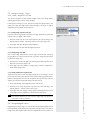
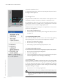
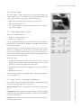
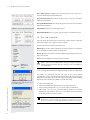
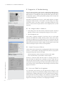
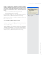
DPV-450
PV ACQUIRE™
FOR AB SCIEX MASS SPECTROMETERS
S O F T WA R E M A N U A L
PV ACQUIRE™
FOR AB SCIEX MASS SPECTROMETERS
S O F T WA R E M A N U A L
REV 02115
REV 02115
1
1
OVERVIEW
O ver view
1.1 I n t ro d u c t i o n
Welcome to the Digital PicoView® Software Instruction Manual. This manual describes the installation and operation of the
PV Acquire Software module to be used with Digital PicoView hardware from New Objective Inc. In addition to being a
useful reference, this manual can be utilized during user training. Storing this manual near the computer operating your Digital
PicoView is highly recommended.
1.2 S o f t w a r e O v e r v i e w
The Digital PicoView® software package consists of two main modules. The first is PV Configure which is used to set up and
configure a default settings file. The second is PV Acquire which is the application that provides the graphical user interface for
the source. PV Acquire enables remote stage positioning, high resolution spray imaging, and advanced features such as Digital
Divert™.
This manual guides you through the installation of PV Configure and PV Acquire software and the source-software communication
hardware. The sections guide you through the daily procedures of software initialization, image optimization, and tip positioning.
Your separate Digital PicoView Hardware Manual is your reference for source assembly, hardware configuration and specific
nanoelectrospray applications.
Additional resources for nanoelectrospray applications can be found in the Tech & App Notes section of the New Objective
website: http://www.newobjective.com/support
D P V- 4 5 0 D I G I TA L P I C O V I E W U S E R M A N U A L
1-3
2 READ THIS FIRST
2
Re a d T his Fir s t
2.1 S a f e t y C o n s i d e r a t i o n s
Electrospray ionization (ESI) involves the use of potentially lethal high-voltage electrical current. Observe all manufacturers’
safety recommendations in the use of such equipment. No equipment modifications should be made except by trained
personnel using methods approved by the manufacturer in accordance with all safety requirements. Installation of equipment
should be performed by qualified personnel in accordance with all applicable electrical codes.
Never use this product with defective, damaged, or faulty equipment. Serious injury or death could result.
Only qualified personnel should use this product. Provide a safe workplace equipped with all necessary safety equipment.
2.2.1 Prior to Installation
Follow all safety recommendations of the equipment manufacturer(s). All system voltages must be brought to ground potential
and all high-voltage contacts disconnected from the inlet system before installation of the Digital PicoView® system.
Inspect all equipment carefully prior to use. Any damaged, chipped, or cracked components should not be used and must be
discarded or repaired.
2.2.2 Handling Fused-Silica Tubing
Handling of fused-silica or glass tubing and tips can result in serious personal injury, including eye and skin injury. Use safety
glasses or goggles meeting ANSI Z87.1-1989 requirements, or the equivalent. Puncture- and chemical-resistant gloves should
also be worn at all times.
2.2.3 Tip Adjustment and/or Replacement
Do not attempt to adjust or replace the tip unless the ESI high voltage and other applicable voltages are turned off and are at
ground potential.
Reduce any applicable backing pressure (liquid, gas, etc.) to ambient before loosening ESI tip fittings and removing the
fused-silica tip or transfer line from the coupling union. Prior to pressurization, make sure that components are tightened to
specifications to prevent separation during use. Failure to adhere to this warning could result in projectile-like expulsion of the
tip from the coupling union, which could cause serious personal injury or damage to surrounding apparatus.
2.2.4 The Transfer Line
D P V- 4 5 0 D I G I TA L P I C O V I E W U S E R M A N U A L
The transfer line connecting to either a tip module or the Micro Injection Valve must not be made from an electrically conductive
material. It must be fabricated from an electrically insulating material such as PEEK™ or fused silica. Otherwise, the operator
may be exposed to potentially lethal voltage.
2-1
WARNING: Do not defeat any mass spectrometer system software or hardware safety interlocks.
2.3 Tr a d e m a r k s
The following trademarks are found in this instruction manual:
Teflon is a registered trademark of E.I. du Pont de Nemours and Co.; QTrap, and TripleTOF are trademarks of AB Sciex;
MicroTight and SealTight are trademarks or registered trademarks of Upchurch Scientific, Inc. a division of IDEX Corporation;
PEEK and PEEKsil are trademarks of Victrex plc; PicoView, Digital PicoView, PicoClear, PicoTip, PicoTip Powered, and PicoFrit
are registered trademarks of New Objective, Inc. IntegraFrit, SilicaTip, TaperTip, GlassTip, and are trademarks of New Objective,
Inc. All other trademarks are the properties of their respective companies.
REV 02115
2 READ THIS FIRST
2. 4 L i m i t e d Wa r r a n t y
DISCLAIMER
Technical information contained in this publication is for reference purposes only and is subject to change without notice.
The information is believed to be reliable and accurate; however, nothing set forth herein constitutes a warranty of any kind or
nature. Given the variety of experimental conditions, New Objective, Inc., cannot guarantee performance at a given flow rate;
the best guide to tip selection and operation is empirical testing.
The user is solely responsible for complying with any patent(s) pertaining to applications or methods using the products
described or mentioned in this manual.
DISCLAIMER OF WARRANTIES
New Objective warrants that PVAcquire Software Product will substantially conform to its specifications during the hardware
period of the New Objective Digital PicoView product.
The warranty on any removable media used to distribute Software Product is provided in the applicable warranty statement. TO
THE MAXIMUM EXTENT PERMITTED BY APPLICABLE LAW, NEW OBJECTIVE AND ITS SUPPLIERS HEREBY DISCLAIM ALL
OTHER WARRANTIES AND CONDITIONS, EITHER EXPRESS, IMPLIED OR STATUTORY, INCLUDING, BUT NOT LIMITED
TO, WARRANTIES OF TITLE AND NON-INFRINGEMENT, ANY IMPLIED WARRANTIES, DUTIES OR CONDITIONS OF
MERCHANTABILITY, OF FITNESS FOR A PARTICULAR PURPOSE AND/ OR LACK OF VIRUSES ALL WITH REGARD TO THE
SOFTWARE PRODUCT. Some states/jurisdictions do not allow exclusion of implied warranties or limitations on the duration of
implied warranties, so the above disclaimer may not apply to you in its entirety.
LIMITATION OF LIABILITY
Notwithstanding any damages that you might incur, the entire liability of New Objective and any of its suppliers your exclusive
remedy for all of the foregoing shall be limited to the greater of the amount actually paid by you separately for the Software
Product or U.S. $5.00 or in-country currency equivalent. TO THE MAXIMUM EXTENT PERMITTED BY APPLICABLE LAW,
IN NO EVENT SHALL NEW OBJECtIVE OR ITS SUPPLIERS BE LIABLE FOR ANY SPECIAL, INCIDENTAL, INDIRECT OR
CONSEQUENTIAL DAMAGES WHATSOEVER, INCLUDING, BUT NOT LIMITED TO, DAMAGES FOR LOSS OF PROFITS
OR CONFIDENTIAL OR OTHER INFORMATION, FOR COST OF COVER, FOR BUSINESS INTERRUPTION, FOR PERSONAL
INJURY, FOR LOSS OF PRIVACY ARISING OUT OF OR IN ANY WAY RELATED TO THE USE OF OR INABILITY TO USE
THE SOFTWARE PRODUCT, EVEN IF NEW OBJECTIVE OR ANY SUPPLIER HAS BEEN ADVISED OF THE POSSIBILITY OF
SUCH DAMAGES AND EVEN IF THE REMEDY FAILS OF ITS ESSENTIAL PURPOSE. Some states/jurisdictions do not allow
the exclusion or limitation of incidental or consequential damages, so the above limitation or exclusion may not apply to you.
D P V- 4 5 0 D I G I TA L P I C O V I E W U S E R M A N U A L
2-2
3
S O F T WA R E C O M P O N E N T S
3 S o f t wa re C o m p o n e n t s
3.1 Host PC System Requirements
3.1.1 PV Acquire is compatible with the following operating systems:
- Windows® 8™, Windows® 7™, Window® XP™- Windows® Vista™, Windows® NT™, Windows® 2000™
- The host PC is required to support two USB 2.0 (or better) connections.
3.2 S o f t w a r e Ch e c k l i s t
-
Digital PicoView® Software Installation media
All of the required application software, device drivers, dll’s, and the National Instruments Run-Time Engine are on this
drive.
-
Digital PicoView Operator’s Manuals
3.3 Hardware Checklist
-
Digital PicoView® Nanospray Source with actuators & camera installed
(See Digital PicoView Hardware Manual for configuration)
USB-to-serial port converter
-
Serial cable for connecting actuators to converter
-
USB Cable for camera to computer connection
D P V- 4 5 0 D I G I TA L P I C O V I E W U S E R M A N U A L
-
3-1
REV 02115
4
S O F T WA R E I N S TA L L AT I O N
4 S o f t wa re I n s t a l l a t i o n
The Digital PicoView® software should be installed and the host PC rebooted
prior to making the USB connections between the Digital PicoView® Camera,
XYZ actuators, and host PC.
4 .1 P V A c q u i r e S o f t w a r e I n s t a l l a t i o n
FIGURE 4.1 Confirm installation
1. Locate the Digital PicoView software.
2. Insert the software media (USB thumb drive)
3. There will be two folders containing software appropriate for your OS; one
will be for 64-bit installation and the other for 32-bit installation. Open the
folder appropriate for your install.
4. Locate the CDStarter.exe file and double-click to launch the installation
application
FIGURE 4.2 Startup dialog box
5. Accept the dialog box by clicking YES. The start-up window appears
6. Click on 1-USB to Serial Install to install the USB-to-serial converter driver.
Follow the default installation instructions.
7. Click 2-Camera Install to install the camera drivers. Follow the default
installation instructions.
8. Click 3-PV Configure Install to install the PV Configure application. Follow
the default installation instructions.
9. Click 4-PV Acquire Install to install the PV Acquire application and National
Instruments™ Run-Time Engine. Follow the default installation instructions.
10. Restart/re-boot the host PC.
The host PC must be rebooted to complete software installation. Do not
connect the USB cables from Digital PicoView Hardware prior to rebooting,
as this will cause software failure.
11. Two Digital PicoView applications have been installed in the Windows®
START menu: Digital PicoView > PV450 Acquire 2_x_x and PV Configure.
12. A successful installation will also result in two icons being added to the
desktop. These icons point to applications for digital camera diagnostic
software. These pointers may be deleted from the desktop at no risk.
13. Additional Installation Notes are available on the software USB drive, follow
these directions should the cdstarter.exe application fail to run.
FIGURE 4.4
Two additional icons
will be added to
the desktop upon
installation. These are
not required and may
be deleted without
risk.
D P V- 4 5 0 D I G I TA L P I C O V I E W U S E R M A N U A L
FIGURE 4.3 Two Digital PicoView
applications are added to the START
menu (Windows® XP shown)
4-1
5
S O F T WA R E & H A R D WA R E I N I T I A L I Z AT I O N
5 S o f t wa re & H a rd wa re I ni t i a li z a t i o n
5.1 C o n n e c t t h e U S B c a b l e s
Prior to using PV Acquire, the USB connections between the host PC and Digital
PicoView® source need to be established. This will be followed by the creation
of a default configuration file using the PV Configure application.
FIGURE 5.1
1. Connect the USB cable from the digital camera to the host PC. Follow
instructions to activate USB driver (if required). (Figure 5.1)
2. Connect the USB cable from the USB-to-serial converter to the host PC.
Follow instructions to activate USB driver (if required). (Figure 5.2)
5.2 S e t t i n g a Po r t A s s i g n m e n t f o r
USB - to - Serial Adapter
The USB-to-serial adapter will be assigned a virtual COM port number by the
operating system. This number needs to be determined and is used by the PV
Configure application to establish a default settings file for PV Acquire.
FIGURE 5.2
1. Open the Windows Device Manager. In Windows XP this is typically found
under: Start > Control Panel (classic view) > System > Hardware Tab (See
Figure 5.3)
2. Click on the Device Manager button
3. The Device Manager List will open. Click on Ports (COM & LPT). Look for
USB Serial Port (ComX) in the sub-list (See Figure 5.4).
4. Note the COM port setting (e.g. COM3, COM4, etc.) that will be seen in
parenthesis (this assignment will be needed when running PV Configure for
the first time).
5.3 S e l e c t i n g a n A l t e r n a t e CO M Po r t ( O P T I O N A L )
If the COM port setting chosen by the operating system is in conflict with
another device, the COM number may be assigned manually. This may resolve
serial port conflicts.
FIGURE 5.3
1. Right-click on the USB Serial Port (ComX) device in the Device Manager list
and select Properties from the pop-up menu (Figure 5.5).
D P V- 4 5 0 D I G I TA L P I C O V I E W U S E R M A N U A L
2. Click on the Port Settings tab.
5-1
3. Click on the Advanced... button.
4. Choose an alternate COM Port Number from the menu list (Figure 5.6).
5. Click the OK button in the Advanced Settings window.
6. Click the OK button in the Properties window.
FIGURE 5.4
REV 02115
5
S O F T WA R E & H A R D WA R E I N I T I A L I Z AT I O N
FIGURE 5.5
FIGURE 5.6
D P V- 4 5 0 D I G I TA L P I C O V I E W U S E R M A N U A L
5-2
6
P V C O N F I G U R E A P P L I C AT I O N
6 P V C o n f i g u re A p p li c a t i o n
PV Configure must be run once prior to the first activation of PV Acquire. The
settings file created by PV Configure is required for the operation of PV Acquire.
6.1 P V C o n f i g u r e O v e r v i e w
FIGURE 6.1
PV Configure generates a default settings configuration file (*.ini file) that PV
Acquire is required to open each time it runs. Think of this much like a “tune
file” for your digital source settings. The default settings configuration file saves
the following information:
COM port assignment
• Number of the COM port for communication with the XYZ Stage through
the USB-to-serial adapter
XYZ Stage Direct Go to Position
• Sets the default XYZ Stage position for the direct go-to position.
FIGURE 6.2
XYZ Stage Retract Position
• Sets the default XYZ Stage position for the retract command
• Used as the retract position for Digital Divert™
Camera Exposure and Gain Settings
• Sets start up values for image brightness and gain
• Camera Acquisition Loop Time
- Sets the acquisition period (in milliseconds) for image acquisition
- Settings below the default value (102 mS) may result in a slow down of the
user interface. The default value yields a frame rate @ 8-10 images/sec.
• Cursor Calibration (Cal X, Cal Y) Values
- Sets the mm calibration value (in µm/pixel) of the on-screen cursors
- Value should ONLY be changed from default settings if the optical tube or
lens is changed from standard configuration.
- Cal X and Cal Y default values are 10.7 µm/pixel
• Poll Stage Position
D P V- 4 5 0 D I G I TA L P I C O V I E W U S E R M A N U A L
- Determines the frequency of polling the stage actuators for position. This
feature is associated with the manual control knobs on the stage controllers
(available on systems prior to 2010).
• Knob Control
- Enables the user to toggle activation of manual control knobs on stage
actuators (available on systems prior to 2010).
• Multiple PV Configure settings files may be used. Each user can have one or
more settings files to accommodate different nanospray configurations.
6-1
• All of the settings, with the exception of the COM port value, may be
changed directly from within PV Acquire.
REV 02115
6
P V C O N F I G U R E A P P L I C AT I O N
6.2 Cr e a t i n g A C o n f i g u r a t i o n S e t t i n g s Fi l e
1. Select PV Configure from the Windows START menu under the Digital PicoView® heading. A dialog box asking you to select
the proper COM port will pop up. (Figure 6.1)
2. Select the COM port number from the menu selection as reported by the Device Manager in section 4.2. In this example
the selected COM port is COM3.
Do not click or type in this pulldown menu. Doing so will corrupt the configuration file making PV Acquire unusable. Select the
Com Port from the pulldown menu only.
3. The main PV Configure dialog window is now available:
4. Select and modify each of the desired configuration parameters.
Guidelines for typical set-up:
- Direct Go To & Retract: default values are good starting points
- Camera Settings:
- Exposure = 20,000 µS
- Gain = 10 dB
- Acquisition Loop Time = 102 mS
- Poll Stage Position Every: OFF
- Knob Control: OFF
- Cal X, Cal Y: Default Values of 10.7 for each
5. Click Save to save the settings file. A standard dialog window will open. The file may be saved under any name, to any userselected directory.
6. Note the file location and file name. Click the OK button to save the file. The PV Configure window will close automatically.
D P V- 4 5 0 D I G I TA L P I C O V I E W U S E R M A N U A L
6-2
7
P V A C Q U I R E 4 5 0 A P P L I C AT I O N
7 P V A c q uire 4 50 A p p li c a t i o n
7.1 P V A c q u i r e S t a r t - u p
FIGURE 7.1
PV Acquire requires user input of the location of the Configuration File each time
it is started. The XYZ stage also requires a Home Stage operation if this is the first
time the software is connecting with the XYZ stage controllers (i.e. installation, or
the power to the stage motors has been interrupted or disconnected). The Home
Stage operation sets the (0,0,0) point for XYZ stage motion. Operation without
establishing the proper Home position will result in erratic stage positioning and
a loss of range of motion.
1. Choose PV Acquire from the Start menu under the Digital PicoView®
heading.
2. A dialog window asking for the location and name of the Configuration File
created in section 6.2 will appear. Choose the File and click OK (Figure 7.1)
3. A second dialog window will open asking if the XYZ stage requires a Home
Stage operation. The Home Stage operation is required if this is the first
use of the stage or if power to the stage motors has been interrupted or
disconnected (Figure 7.2)
FIGURE 7.2
A Home Stage operation must be performed when the Digital PicoView
stage is used for the first time OR if power to the unit’s XYZ stage has been
disrupted or disconnected.
5. Click OK in the message box to begin using PV Acquire (Figure 7.3).
7.2 O v e r v i e w
FIGURE 7.3
One of the most useful features of the Digital PicoView platform is the smart
XYZ motor controls used for stage actuation. Each controller is an independent
microprocessor driven device; The Digital PicoView platform can be used
without the PV Acquire application. It also ensures that the stage position and
spray performance will not be effected if PV Acquire is exited unexpectedly. PV
Acquire can be readily re-started without effecting the stage position.
D P V- 4 5 0 D I G I TA L P I C O V I E W U S E R M A N U A L
7-1
PV Acquire™ is a powerful user interface for Digital PicoView enabling a
high level of productivity for nanospray enabled mass spectrometry. The user
interface supplies an interactive digital image of the MS inlet and the necessary
controls for XYZ stage positioning. Advanced features such as Digital Divert™
enable the remote control of emitter XYZ position from other instruments such
as autosamplers, or liquid chromatographs.
REV 02115
7
Interface Feature
Performance
Sec.
Main Window
Choose Settings, Source Image, or Diagnostics
7.2.1
Measurement Cursor
User drag-and-drop placement for distance 7.7
measurement
and
establishing
P V A C Q U I R E 4 5 0 A P P L I C AT I O N
reference
positions
Cursor Readout
Shows X, Y distance (mm) between cursor
7.7
centers
Image Controls
Real Time Camera Exposure, Gain, Image 7.3,
Magnification, and Image Tool controls
7.4, 7.5
Stage Control Panel
Buttons enable precise XYZ jogging of stage
7.8
Digital Divert™ Panel
Remote (contact closure or digital input) 8.3
FIGURE 7.4 Primary PV Acquire™
window
switching between spray and retract/rinse
position
Mode Panel
Choose Tune, Store, Go To, or Retract & Home
7.2.2
Tabs for In-depth control features
7.2.1 S e t t i n g s Ta b s
The Settings tabs, found at the top of the main window, offer three levels of
control: Settings, Source Image, and Diagnostics (Figure 7.5).
Main Window
Button/Feature
Comment
Source Image Tab
Exposure, Gain, Apply
Controls Camera Exposure Time
and Image Gain
Source Image Tab
Image Magnification
Sets
the
Digital
Magnification Value
Source Image Tab
Image Tool
Selects Cursor, Mouse
Mouse Zoom modes.
Source Image Tab
Pan X, Pan Y
Sets image shift values when
using Image Mag Values of 2 or
3X.
Settings Tab
Acquisition Loop Time
Controls refresh rate of source
image from camera, default
value of 102 mS.
Settings Tab
Stage Polling
This feature is not active in
later software versions (v1.5x
and later) where the stage
controllers have no manual
knobs. Controls how often PV
Acquire communicates with
Stage Controllers. Used when
lots of manual (knob) positioning
is used.
Settings Tab
Cal X, Cal Y
Cursor measurement calibration
values, typically these are NOT
changed from default values.
Settings Tab
Knob Controls
Defeats the manul knob controls
of the XYZ stage controllers. This
feature is inactive with hardware
version later than 2010.
Diagnostics Tab
CCD Camera
Communication and error values
with Camera - Readback only
FIGURE 7.5 PV Acquire™ Settings tab
Image
Pan,
D P V- 4 5 0 D I G I TA L P I C O V I E W U S E R M A N U A L
7-2
7
P V A C Q U I R E 4 5 0 A P P L I C AT I O N
Diagnostics Tab
Cursor Data
Displays Raw Cursor information,
used for recalibration of Cal X,
Cal Y Values. Readback only.
Diagnostics Tab
Configuration File Path
File path of the Configuration
Settings File chosen at start-up.
Readbcak only.
Diagnostics Tab
Com Port Assignment
Value of the COM Port
assignment. Readback only.
Diagnostics Tab
Path
Folder location for saving Digital
Divert screengrab images. Active
field.
to
save
Digital
Divert sceengrab
FIGURE 7.6 Camera exposure setting
too high
7.2.2 M o d e Pa n e l – A d v a n c e d Fe a t u r e C o n t ro l s
FROM 550
Mode Panel
Button/Feature
Comment
Tune Tab
Retract Tip
Moves stage from Current Position to
the Retract Position as defined on the
Retract & Home tab
Tune Tab
Restore Tip
Moves stage from retract position to
last used current position
Tune Tab
EXIT
Preferred way to quit PV Acquire
application. Properly releases all
memory resources and asks if
update to settings configuration file
is desired.
Tune Tab
Update Manual Pos
Software communicates with XYZ
stage controllers. Checks to see if
stage has been moved using manual
control knobs. This features is
inactive for systems after 2010 with
no manual knobs.
Store Tab
Save Position
Saves a position file to disk which
contains the current XYZ stage
position
Store Tab
Load Position
Loads a previously saved position file
and moves the XZY stage to saved
positions
Store Tab
Save Cursor
Creates and saves a cursor position
file which contains the current cursor
position
FIGURE 7.7 Camera exposure
optimized
Position
D P V- 4 5 0 D I G I TA L P I C O V I E W U S E R M A N U A L
Store Tab
7-3
Load Cursor
Position
Go To Tab
Direct X, Direct
Y, Direct Z
Sets the coordinates for direct stage
control
Go To Tab
Apply
Moves the Stage to position defined
by Direct X, Direct Y, Direct Z
Retract & Home Tab
Retract X, Retract
Sets the coordinates of the Retract
Position
Y, Retract Z
REV 02115
Loads a previously saved cursor
position, repositioning the cursor to
the loaded position
Retract & Home Tab
Retract Tip
Moves the Stage to the Retract
Position defined by Retract X, Retract
Y, Retract Z
Retract & Home Tab
Home Stage
Performs Home Stage Operation
7
P V A C Q U I R E 4 5 0 A P P L I C AT I O N
7.3 I m a g e S e t t i n g s: E x p o s u r e, G a i n, A c q u i s i t i o n T i m e
The camera acquisition controls enable complete control over image quality
enabling optimal spray, inlet or emitter imaging.
FIGURE 7.8 Camera acquisition controls
If the Exposure setting is too low, the Source Image will appear black. If the
setting is too high, the image will be washed out (Figure 7.6). Figure 7.7 depicts
adjustments set for optimal camera exposure.
7.3.1 Setting Image Exposure Time (µS)
Exposure controls image quality with respect to image illumination, just like the
exposure time of a digital or film camera.
FIGURE 7.9 Image tools drop-down
menu
1. Place the mouse over the arrow on the Exposure (µS) scale and drag to the
desired position (50,000 - 100,000 µs works in most cases) (Figure 7.8).
2. Click Apply and note changes in image brightness.
Continue adjustment to attain desired brightness/contrast.
7.3.2 Setting Image Gain (dB)
Gain controls image enhancement, contrast range, and noise level. Increasing
the gain allows for a shorter exposure time (e.g. used to image spray dynamics)
but increases image noise.
1. Click the arrow on the Gain (dB) scale and drag to the desired position (8-10
dB works in most cases) (Figure 7.8).
2. Click Apply and note changes in image quality. Continue adjustment to
attain desired image clarity.
7.3.3 Setting Acquisition Loop Time (mS)
Acquisition Loop Time controls the image refresh rate. A low setting (< 50 mS)
can be used to monitor spray dynamics and is useful to observing transient spray
behavior. Settings below 100 mS can compromise the response time of the PV
Acquire user interface and possibly lead to interface lock-up.
1. Click on the Settings tab in upper left corner of the screen
3. Click Apply and note changes in image quality in the Image Preview screen
on the right. Continue adjustment to attain desired image clarity.
Decreasing Acquisition Loop Time increases image frame rate but lowers
performance of the user interface.
7. 4 I m a g e M a g n i f i c a t i o n
Magnifying the Source Image to 1X, 2X, and 3X provides digital magnification of
fine image details. Radio buttons located in the lower right corner of the Source
Image screen allow rapid transition from one magnification level to another; 1X
D P V- 4 5 0 D I G I TA L P I C O V I E W U S E R M A N U A L
2. Click the arrow on the Acquisition Loop Time (mS) scale and drag to the
desired position (~ 100 mS works in most cases).
7-4
7
P V A C Q U I R E 4 5 0 A P P L I C AT I O N
is the default magnification level.
To change magnification level, click the corresponding radio button and wait for
the image to refresh (Figure 7.9).
7. 5 I m a g e To o l s
Image Tools define available mouse modes when the mouse is placed over the
image display. Availability of Image Tools depends on magnification level.
At 1X magnification, Select Cursor is the only active Image Tool. Select Cursor
transforms the mouse into a crosshair cursor (+), allowing the user to move the
green reference cursor in the Source Image display screen.
FIGURE 7.10 Pan X and Pan Y scroll
bars
Additional tools activate upon selecting 2X or 3X magnifications. These tools are
grayed-out at 1X magnification.
1. Select a higher magnification level.
2. Click the dropdown menu immediately below Image Tools and select desired
tool (Figure 7.9).
7.5.1 Image Panning with the Mouse
Pan converts the crosshair cursor to a hand to allow manual image panning.
Mouse panning position is reset each time the magnification is changed.
1. Select Pan in the Image Tools dropdown.
2. Place the hand cursor over image display.
3. Click and drag to “pull” desired image components into view.
7.5.2 Image Zooming with the Mouse
Zoom In and Zoom Out functions allow image display expansion and contraction.
1. Select Zoom In from the Image Tool dropdown.
2. Click in the image display.
FIGURE 7.11 Use the Copy Data
feature to copy images to the clip board
for use in other applications
7.5.3 Panning Scrollbar
The Pan X and Pan Y scrollbars in the lower left corner of the Source Image
tab provide horizontal and vertical scrolling, respectively. Panning enables you
to move the observable image space at 2X and 3X magnifications. Unlike the
mouse panning option, Pan X and Pan Y scrollbar settings are saved when image
magnification settings are changed.
D P V- 4 5 0 D I G I TA L P I C O V I E W U S E R M A N U A L
7-5
3. To return to initial magnification, click Zoom Out from the Image Tools dropdown
or select 1X magnification to return the image to default settings.
1. Select either 2X or 3X from Image Magnification.
2. Click either the Pan X or Pan Y arrow and drag to the desired position (Figure 7.10).
The Pan, Zoom In, and Zoom Out options from the Image Tools dropdown
and the Pan X and Pan Y scrollbars are only active at the 2X and 3X image
magnifications.
REV 02115
7
P V A C Q U I R E 4 5 0 A P P L I C AT I O N
7.6 S a v i n g I m a g e s
The Source Image is readily captured with a copy-and-paste operation into
another application such as Windows® Paint. The background image and
cursors will be saved, the cursor distance readout, however, is not.
1. Right clicking in the image window will bring up a pop-up menu.
2. Select Copy Data (Figure 7.11).
3. Use a paste operation in another suitable application such as Paint or
Microsoft ® Powerpoint ®
7. 7 U s i n g M e a s u r e m e n t Cu r s o r s
FIGURE 7.12 Measurement cursors
provide precise reporting on distance
between the two cursor positions
There are two measurement cursors:
Blue Cursor – GS1 gas nozzle cursor
Green Cursor – emitter cursor
Cursors are placed with a drag-and-drop mouse operation using the left mouse
button.They are a powerful tool for establishing, repeatable emitter protrusion
from the GS1 gas nozzle.
Typically the blue cursor is placed at the front of the GS1 gas nozzle, and the
green cursor is placed at the tip of the emitter. The Cursor Readout will then
show the precise distance between the end of the gas nozle and emitter tip.
Use this value to adjust the tip protrusion from the gas nozzle. Ideal protrusion
distance is between 1.5mm and 2.0mm.
FIGURE 7.13 Stage control panel
To position a cursor:
1. Position the mouse cursor over either screen cursor. The mouse cursor will
change shape from a solid to hollow cross. (Note the blue cursor is a center
marked line, and should be grabbed at the center mark.)
2. Left click-and-hold the mouse while dragging the screen cursor to the desired
position.
3. Release the mouse button.
The Cursor Readout will show an updated distance measurement between the
two cursors. (Figure 7.12)
You can easily control XYZ position of the emitter tip using the Stage Control
commands in the upper right corner of your screen.
The Stage Control contains two fields and six positioning commands (Figure
7.13).
Crash Limit defines the maximum forward tip Y distance (µm) before colliding
with the mass spec inlet. While the default limit is 12,500 µm, you can customize
the value for each emitter.
Step Size is the incremental distance (µm) traveled by the tip when you press any
of the Stage Control buttons.
D P V- 4 5 0 D I G I TA L P I C O V I E W U S E R M A N U A L
7.8 S t a g e C o n t ro l C o m m a n d s & Pa r a m e t e r s
7-6
7
P V A C Q U I R E 4 5 0 A P P L I C AT I O N
The L and R arrows (Left/Right) move the tip along the source X-axis by an
increment defined by the selected Step Size.
The In and Out arrows move the tip along the source Y-axis by an increment
defined by the Step Size.
The Up and Down buttons move the tip along the source Z-axis by an increment
defined by the Step Size.
FIGURE 7.14 Tune tab In the Mode panel
Stage Position reports the current stage position.
Stage Retracted LED turns on (green) when the stage is in the Retract Positon.
7.9 Tu n e Ta b C o m m a n d s
Tune tab within the Mode panel contains basic emitter-actuator positioning
functions and allows you to properly exit PV Acquire™ .
FIGURE 7.15 Retract & Home panel
Click the Tune tab in the Mode panel (Figure 7.14)
Retract Tip moves the emitter to the Retract, X, Retract Y, Retract Z coordinates,
as set on the Retract & Home tab of the Mode panel.
Restore Tip moves the emitter to the last established position before the retract
button was pressed
EXIT saves the configuration and safely quits PV Acquire.
FIGURE 7.16
Stage position
settings
Always click on the EXIT button when closing PV Acquire. Closing the
software using other methods may leave memory resources unavailable to
other applications.
7.10 U s i n g A u t o m a t e d S t a g e Po l l i n g ( I n a c t i v e Fe a t u r e )
FIGURE 7.17 Dialog window
confirming that the stage has been reset
to the home position
PV Acquire can periodically poll the XYZ stage for its current position
automatically if you are uncertain that the values reading in the software program
match those of the stage. This would only happen if your stage was moved using
the manual control knobs (not available on models after 2010).
1. Click on the Settings tab.
D P V- 4 5 0 D I G I TA L P I C O V I E W U S E R M A N U A L
2. Click and hold the Poll Stage Position Every (s) drop-down menu.
7-7
3. Select a polling interval time of 5, 10 or 30 seconds (recommended).
4. Click Apply. You may verify automated polling operation by manually
adjusting the stage position using one or more knob control(s) and waiting
for the Stage Position window to update.
Using a short stage polling time (5 or 10 seconds) can result in poor
performance of the PV Acquire user interface on certain host PC’s since
portions of the interface are unavailable during the update position operation.
FIGURE 7.18 When restarting PV
Acquire, the rompt to home the stage
can be declined if power to Digital
PicoView has remained on
REV 02115
7
P V A C Q U I R E 4 5 0 A P P L I C AT I O N
7.11 S e t t i n g Re t r a c t Po s i t i o n
The Retract Position is typically used in two different operations: (1) Moving the emitter far from the MS inlet making it easier to
change emitters or clean the inlet etc. (2) Establishing the emitter position for use with the Digital PicoView rinsing station. The
XYZ stage is retracted through the Retract Tip button from the Tune or Retract & Home tab of the Mode panel. The actual XYZ
stage position of the Retract Position is set on the Retract & Home panel (Figure 7.15).
1. Select on the Retract & Home tab of the Mode panel.
2. Click the Retract Tip button. The stage will move to the settings set by Retract X, Retract Y, and Retract Z values.The Stage
Retracted LED will light up.
3. Note the position of the XYZ stage. If a different Retract Position is desired, type the new value(s) into Retract X, Retract Y,
and/or Retract Z.
4. Click on Retract Tip to move to the new Retract Position.
5. Repeat steps 3-4 until the final desired position is obtained.
6. Go to the Tune tab of the Mode panel and click Restore Tip to return the XYZ stage to the last operating position.
7.12 S e t t i n g H o m e Po s i t i o n
The Home Position is defined at the (0, 0, 0) setting of the XYZ stage. The Home Position is an absolute reference position that
both PV Acquire and the motor actuators use in making XYZ stage movements. A Home Position operation must be performed
when the Digital PicoView source is used for the first time. A Home Position operation must also be performed if the electrical
power to the motor actuators has been disrupted or disconnected.
If you are merely re-starting PV Acquire and the power to the Digital PicoView source has remained intact, a Home Position
operation should not be required.
1. Click on the Retract & Home tab of the Mode panel.
2. Click the Home Stage button. The stage controls will gray out during the homing operation.
3. When the homing operation is finished the Stage Position will read (0, 0, 0) and a dialog window will appear confirming that
the stage has been homed (Figure 7.17).
The current operating position of the XYZ stage will be lost when the home position operation is performed.
7.13 Q u i t t i n g P V A c q u i r e
1. Click on the Tune tab in the Mode panel
2. Click on Exit. A dialog box will appear asking if you want to update the default configuration file with the currently selected values.
3. Select Yes if you wish to: 1) modify the existing configuration file or 2) create a new configuration file with the most recently
used Digital PicoView operating parameters. If you answer yes, you will be prompted with a standard file dialog window.
4. The only other way to exit the program is through the Windows Task Manager Control Panel (CTL-ALT-DEL), but this method
is not recommended.
Always click EXIT before closing the PV Acquire window. Closing the software using other methods may leave memory
resources unavailable to other applications.
D P V- 4 5 0 D I G I TA L P I C O V I E W U S E R M A N U A L
The proper way to quit PV Acquire is to always click Exit from the Tune tab of the Mode panel when closing PV Acquire.
Closing the software using other methods may leave background processes running and memory resources unavailable to other
applications. While other methods such as directly closing the program window through the Microsoft Windows buttons or
using the application stop button will work to terminate the program, it is not a best practice with PV Acquire. Using the Exit
button ensures that all PV Acquire functions are termintated properly and that saved settings will be retained.
7-8
7
P V A C Q U I R E 4 5 0 A P P L I C AT I O N
7.14 Re - S t a r t i n g P V A c q u i r e
PV Acquire can be re-started with the procedure in section 7.1. However, as long as the power to the Digital PicoView XYZ
stage has remained intact from the last use, there is no need to execute a Home Stage operation.
The user may safely decline the Home Stage request on re-start (see Figure 7.18).
This way the stage position, spray operation, etc. of the source will not be disturbed during the PV Acquire re-start sequence.
D P V- 4 5 0 D I G I TA L P I C O V I E W U S E R M A N U A L
PV Acquire may be exited and re-started without disturbing the physical operation (stage position, spray voltage etc.) of the
Digital PicoView source provided that a Home Stage operation is NOT performed on re-start.
7-9
REV 02115
8
A D VA N C E D F E AT U R E S
8 A d va n c e d Fe a t u re s
8.1 S t o r e C o m m a n d s
Store tab in the Mode panel contains functions for storing and re-loading stage and cursor position files you select (Figure 8.1).
The position and cursor information is stored as a date and time stamped text file. The name of the file may be changed to a
title selected by the user.
8.1.1 Save Cursor Position
1. Click on the Go To tab
2. Click Save Position to save the current emitter position and cursor setting in a position file.
3. Click Load Position to load a position file that will restore the cursor and stage to the position contained in that position file.
Once the file is loaded, the stage will move to the saved position and the stage will move to the new coordinates.
8.1.2 Save Position
1. Click on the Store tab
2. Click Save Cursor Position to save the current cursor setting.
3. Click Load Cursor Position to load a cursor position file that will restore the cursors to the positions contained in that
previously saved position file.
Once the file is loaded, the stage will move to the saved position and the stage will move to the new coordinates.
8.3 D i g i t a l D i v e r t™
Digital Divert™ is a powerful feature that enables remote toggling of the XYZ stage position between the spray and retract
positions. The feature saves both the spray and retract positions, and your emitter can move between them with precision at a
time interval of your choosing. PV Acquire will take pictures of the spray at each interval for evidence of spray stability. Control
is via a low level intergace, either a traditional contact closure or digital (TTL compatible) control signal with a third party
hardware platform.
Another instrument (mass spectrometer, autosampler, liquid chromatograph, etc.) can then be used to control whether the
nanospray emitter is in the operating (spray) position or the retracted (rinse) position. The combined system ensures that both
the mass spec inlet and emitter stay as clean as possible during repetitive LC-MS/MS runs. For example, some LC’s provide a
so-called “Run out” signal that is actively true when a gradient is being delivered. This can be used to enable Digital PicoView to
position the emitter in the spray position during gradient elution and in the rinse position for loading, column conditioning, etc.
8.3.1 Setting up Digital Divert
The easiest way to connect Digital Divert to your MS is through an LC system. Please check your LC manual for more information
on connecting interfaces like Digital Divert.
Before activating your Digital Divert Box, you should set the coordinates of your spray and retract (wash) positions; the spray
positions are in the upper right hand corner in the Stage Control section and the retract positions are in the lower right under the
Retract & Home tab. See the hardware manual for more information. If you are not interested in retracting your tip during spray
but would like screen shots at intervals you choose, simply match the coordinates of the retract position to those of the spray.
D P V- 4 5 0 D I G I TA L P I C O V I E W U S E R M A N U A L
The Digital Divert interface is made available through the Digital PicoView source camera. A cable and interface box connected
to the camera provides the connection point for the interface. Refer to the Digital PicoView Hardware Manual for instructions
on making the physical interface connections and setting up the emitter rinsing station.
8-1
8
A D VA N C E D F E AT U R E S
1. A positive and negative wire should be connected to the Digital Divert box
(pins 1 and 4). Make sure that the wire running from +5V (pin 1) runs to the
positive terminal) on the machine you’re interfacing with.
2. Connect the Digital Divert box to the top of the Digital PicoView source
camera using the serial cable provided. This provides the interface connection.
When connecting Digital Divert with Eksigent LC systems, see Section 8.4 for
specific contact closure instructions
FIGURE 8.1
8.3.2 Configuration Choices
The Digital Divert™ interface gives a choice over the type of control (contact
closure or TTL compatible) and the polarity of the interface. The type of control
is determined by the selected control channel.
FIGURE 8.2
Toggle Digital
Divert ON
Channel Selection:
Channel 0 is for conventional contact closure and requires an actual contact
between pins 1 and 2 of the Interface Box. The input is true when the contact
is closed. The Channel 0 LED will light when the contact is closed.
Channel 1 is for a TTL level compatible digital signal. The input is true when
the voltage between pins 3 and 4 of the interface box is approx. 2.3-2.8 V or
greater (5 V max.). The Channel 1 LED will light when the voltage is high.
Divert when input is:
FIGURE 8.3 Digital Divert configuration
PIN 1
False will divert the XYZ stage to the retract position when the channel is
false. When the channel is true the XYZ stage will be in the spray position.
PIN 2
PIN 3
PIN 4
+5V plug
D P V- 4 5 0 D I G I TA L P I C O V I E W U S E R M A N U A L
FIGURE 8.4 Digital Divert Interface Box
8-2
True will divert the XYZ stage to the retract position when the channel is
true. When the channel is false the XYZ stage will be in the spray position.
The desired operating (spray) and retract (rinse) positions should be fine
tuned before activating the Digital Divert feature.
8.3.2.1 Using the Modified Digital Divert™ Box
The modified digital divert box consists of a standard digital divert box which
has been modified to be compatible with open collector inputs. The modified
digital divert box includes a 5 kOhms resistor, which connects pins 1 and 3
and a jumper wire which connects pins 2 and 4. Connect the positive wire to
pin 1 on the digital divert box and the negative (or ground) wire to pin 4. Select
Channel 0 in the software under ‘Divert Input Channel’ when using the modified
Digital Divert box.
8.3.3 Activating Digital Divert
1. From the main PV Acquire window, select the ON Digital Divert radio
button (Figure 8.2). The Mode panel will gray-out, preventing access to other
PV Acquire features.
2. A window will pop up that asks you to create a file name; this is for the
automatic screen shots that will be taken at each position change. We
suggest creating a separate folder for these screen shots as the PV Acquire
REV 02115
8
A D VA N C E D F E AT U R E S
will automatically save other information about your Digital Divert toggling
in similar formats. After you create a method, the system will take a screen
shot at the very beginning of the method.
3. Select Channel 0 or Channel 1 from the Divert Input Channel 1 drop-down
menu (Fig. 8.3).
4. Select True or False from the Divert When Input Channel 1 is drop-down menu.
5. Digital Divert is now ready for operation.
6. Digital Divert may be turned off at any time by clicking the OFF radio button.
8.3.5 Testing Digital Divert™
1. To test basic operation, connect two 6” insulated wires—with ends stripped
1/2” bare—between pins 1 and 2 of the Digital Divert Control Interface Box.
FIGURE 8.5 The Digital Divert Interface
box connected to a cable that runs to the
Digital PicoView source camera
2. Set Digital Divert ON and set to Channel 0 with positive True.
3. Twist the two wires into electrical contact. The Channel 0 LED should light
green. If the Channel 0 LED does not light, check to see that the Control
Interface Box power supply is plugged in.
The XYZ stage should begin a movement to the retract position. The Stage Retract
LED will then light green. Disconnecting the wires should cause the Channel 0
LED to go dark, with a return of the XYZ stage to the last used operating position.
8.3.6 Digital Divert Control Buffer
The Digital Divert interface input contains a memory buffer that will toggle the
stage position for every change in command state from false/true. Undesired
changes in channel input state should be avoided, especially if they occur on a
time scale that is shorter than the transit time of the XYZ stage between positions.
FIGURE 8.6 Create a folder and
name it apprpriately to save other timestamped files to. The first green bar
in Digital Divert will light up when the
contact is closed.
When Digital Divert is activated, all stage controls are grayed out and
deactivated. Additionally, if manual knob control was activated, this is also
automatically turned off to prevent any unintentional stage movement.
8. 4 C o n f i g u r e t h e D i g i t a l D i v e r t I n t e r f a c e B o x
1. Required Materials
Parts supplied with the DPV-450 Digital PicoView Nanospray ion source
•
•
•
•
•
•
Digital Divert box
Power supply
DB-9 serial cable
Signal cable
Small screw driver
External interface cable (Only when connecting to an ekspert™
nanoLC 400 system, supplied with the LC system)
D P V- 4 5 0 D I G I TA L P I C O V I E W U S E R M A N U A L
The Digital PicoView Nanospray Source Hardware Manual contains information
on installing and configuring the Digital Divert interface box. Depending
on the model, the Eksigent system uses use either TTL or contact closure to
communicate with the ion source. The instructions below describe how to
configure the Digital Divert box regardless of signaling method.
8-3
7
P V A C Q U I R E 4 5 0 A P P L I C AT I O N
2. Connect the Digital Divert box to the DPV-450 Digital PicoView nanospray ion source
1. Connect the DB-9 serial cable:
a. Connect one end of the DB-9 serial cable to the digital camera.
b. Connect the other end of the DB-9 serial cable to the back of the Digital Divert box.
2. Connect the power supply to the side of the Digital Divert box.
3. Connect the signal cable to the Digital Divert box:
a. Connect the black wire to pin 4.
b. Connect the white wire to pin 1.
FIGURE 8.7 Cable Connections on the Digital Divert Interface Box
3. Based on the LC configuration, connect the other end of the signal cable:
• For a cHiPLC® system (regardless of the LC system):
a. Connect the black wire to GND on the back of the cHiPLC system.
D P V- 4 5 0 D I G I TA L P I C O V I E W U S E R M A N U A L
b. Connect the white wire to VLV A (refer to Figure 8.7).
8-4
FIGURE 8.8 Cable Connections on the cHiPLC System Connectors
• For an ekspert nanoLC 400 system:
Use the connector on the cHiPLC segment of the bifurcated external interface cable and follow the instructions above for
the cHiPLC system (refer to Figure 8.8). The connector does not have to be connected to anything, it is just used to connect
the wires.
REV 02115
7
P V A C Q U I R E 4 5 0 A P P L I C AT I O N
• For a NanoLC Ultra® system:
a. Connect the black wire to CMN or GND on the back of the LC. Use the channel that will control the divert; usually this
is the elution channel.
b. Connect the white wire to RUN Out of the same channel (refer to Figure 8.9).
FIGURE 8.9 Cable Connections on the nanoLC Ultra, NanoLC, or Tempo Systems
• For a NanoLC™ or Tempo™ system:
a. Connect the black wire to GND or CMN on the back of the LC. Use the channel that will control the divert; usually this
is the elution channel.
b. Connect the white wire to RUN Out of the same channel (refer to Figure 8.9).
D P V- 4 5 0 D I G I TA L P I C O V I E W U S E R M A N U A L
8-5
9
DIAGNOTICS & TROUBLESHOOTING
9 D i a g n o s t i c s & Tro u b l e s h o o t in g
The error detection features of PV Acquire™ enable rapid trouble-shooting of
software and/or hardware problems. Errors are detected either through pop-up
dialog windows or in the Diagnostics tab of the main window. Recovery from an
error generally requires correcting the problem, quitting from PV Acquire and
re-starting the application.
FIGURE 9.1 Settings tab
Fortunately recovering from such errors is often simple and does not require
changing the emitter position or interruption of the ESI voltage. The unique,
autonomous nature of the motor actuators of the Digital PicoView® source
ensures a crash of the PV Acquire software will not negatively affect your MS
acquisition.
9.1 N o I m a g e V i s i b l e i n W i n d o w
1. In the Settings tab of the main window, Check the Exposure (20,000 µS
typically) and Gain control (10 dB typically) settings for non-zero values.
2. Check the Diagnostics tab
FIGURE 9.2 Diagnostics tab showing all
camera connections are stable
If the camera is properly connected to the host PC all error codes should
read zero. All handle OUT variables will have positive values. If the camera
connection has failed, the error code Dev Open or error code Get Dev will read
back a negative value. Driver Handle OUT will read zero. Check the connection
cable, then quit and restart PV Acquire. Simply reconnecting the camera cable
without re-starting PV Acquire will not correct the problem.
9.2 S e r i a l C o n n e c t i o n Fa i l u r e
A failure of the serial connection (such as unplugging the cable) to the XYZ stage
controls, or a power failure to the stage motors, may result in a pop-up error
message showing a VISA session lost message:
D P V- 4 5 0 D I G I TA L P I C O V I E W U S E R M A N U A L
FIGURE 9.3 Diagnostics tab showing
USB cable interruption
9-1
Check all stage motor cable connections and motor power supply.
Correct any disconnects, quit and then re-start PV Acquire.
Sometimes a connection failure will NOT result in a message; instead, your
stage will simply not respond to the commands you send it. Make sure you
check all stage connections before trying to move the stage. Sending too many
commands to a disconnected stage can cause the PV Acquire software to freeze.
If the software freezes, open the Windows Task Manager (ctrl-alt-del), end the
program, and restart it.
9.3 I n c o r r e c t CO M Po r t A s s i g n m e n t
FIGURE 9.4 Diagnostics tab
REV 02115
If you disconnect and reconnect your XYZ stage from the USB port in your
computer, the computer may automatically reassign COM port numbers to the
attached devices. Adding another device may also reassign COM port numbers.
If there have been any device changes in your USB port, you should confirm
the number of the correct COM port for PV Acquire by disconnecting your XYZ
stage and reconnecting it (see section 5.2 for assigning port numbers).
9
DIAGNOTICS & TROUBLESHOOTING
Choosing an incorrect COM port assignment in PV Configure™ will result in
painfully slow and repetitive (at least six) pop-up window error messages similar
to the following, showing a VISA Timeout Expired message. This error occurs
because your PV Acquire program is unable to communicate with the stage
properly:
If this occurs start the Windows® Task Manager (CTL-ALT-DEL)
Locate and end the PV Acquire 1_*.exe process:
It is recommended that, after errors occur with PV Acquire, the host PC is
rebooted to prevent any additional downstream errors from occuring.
FIGURE 9.5 Error message for incorrect
COM port assignment
Repeat the process in Section 5.2 Setting a Port Assignment to determine the
proper COM port assignment.
9. 4 P V A c q u i r e™ U s e r I n t e r f a c e Froz e n
The user interface can freeze or lock-up if too many mouse clicks occur before
the program can respond. This is typically problematic when the camera’s
Acquisition Loop Time parameter (found under the Settings tab in the main
window) is set below 50 mS.
The most efficient way to fully recover from lock-up is to go to the Windows
Task Manager, end the PV Acquire 1_*.exe process and re-start the application.
It is recommended that after errors occur with PV Acquire that the host PC is
rebooted to prevent any additional downstream errors from occurring.
D P V- 4 5 0 D I G I TA L P I C O V I E W U S E R M A N U A L
9-2
D P V- 4 5 0 D I G I TA L P I C O V I E W U S E R M A N U A L
7
9-3
P V A C Q U I R E 4 5 0 A P P L I C AT I O N
REV 02115
P V A C Q U I R E 4 5 0 A P P L I C AT I O N
7
D P V- 4 5 0 D I G I TA L P I C O V I E W U S E R M A N U A L
9-4