1
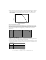
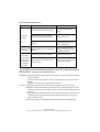
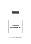
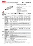
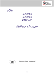
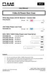
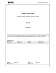
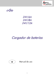
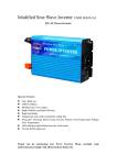
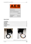
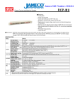
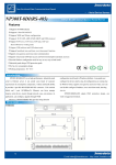
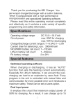
PB-300 / 360
USER'S MANUAL
Sunpower (UK) Ltd
Tel: +44 (0)118 981 1001 Fax: +44 (0)118 981 2002 E-mail: [email protected]
SPECIFICATION : PB-300
MODEL
PB-300P/N-12
PB-300P/N-24
BOOST CHARGE VOLTAGE
14.4V
28.8V
FLOAT CHARGE VOLTAGE
13.6V
27.2V
VOLTAGE ADJUSTABLE RANGE 13 ~ 14.7V
26 ~ 28.8V
RECOMMENDED BATTERY
80 ~ 200Ah
OUTPUT CAPACITY(AMP HOURS)(Note 5)
40 ~ 125Ah
INPUT
BATTERY TYPE
Open & Sealed Lead Acid
OUTPUT CURRENT(max.)
20.85A
10.5A
CONTINUOUS OUTPUT
CURRENT (Typ.)
(Note 6)
12.5A
6.25A
VOLTAGE RANGE
90 ~ 132VAC / 180 ~ 264VAC selected by switch
FREQUENCY RANGE
47 ~ 63Hz
EFFICIENCY (Typ.)
85%
POWER FACTOR (Typ.)
>0.65 (with P type) at 230VAC
AC CURRENT (Typ.)
6A/115VAC
INRUSH CURRENT (Typ.)
COLD START 60A
LEAKAGE CURRENT
<3.5mA / 240VAC
86%
3A/230VAC
90 ~ 110% rated output current
OVER LOAD
PROTE- REVERSE POLARITY
CTION
OVER VOLTAGE
OVER TEMPERATURE
FUNCTION REMOTE CONTROL (CN5)
WORKING TEMP.
Protection type : Constant current limiting, recovers automatically after fault condition is removed
By internal fuse
15 ~ 17V
30 ~ 35V
Protection type : Shut down o/p voltage, re-power on to recover
Protection type : Automatically derate charge current until zero
Open: Normal work
-10 ~ +40
Short: Stop Charging
(Refer to output load derating curve)
20 ~ 90% RH non-condensing
WORKING HUMIDITY
ENVIROSTORAGE TEMP., HUMIDITY -40 ~ +85 , 10 ~ 95% RH
NMENT
TEMP. COEFFICIENT
0.05%/ (0 ~ 45
VIBRATION
10 ~ 500Hz, 2G 10min./1cycle, 60min. each along X, Y, Z axes
SAFETY STANDARDS
EN60335-2-29 CB Approved by TUV
WITHSTAND VOLTAGE
I/P-O/P:3KVAC I/P-FG:1.5KVAC O/P-FG:0.5KVAC
SAFETY &
ISOLATION RESISTANCE
I/P-O/P, I/P-FG, O/P-FG:100M Ohms/500VDC
EMC
(Note 4)
EMI CONDUCTION & RADIATION Compliance to EN55022 (CISPR22) Class B
HARMONIC CURRENT
Compliance to EN61000-4-2,3,4,5,6,8,11; ENV50204, EN55024, Light industry level, criteria A
MTBF
115.8Khrs min.
OTHERS DIMENSION
PACKING
NOTE
Compliance to EN61000-3-2,-3 (only P type)
EMS IMMUNITY
MIL-HDBK-217F (25
)
253*135*48.5mm(L*W*H)
1.45Kg; 6pcs/9.7Kg/0.93CUFT
1. All parameters NOT specially mentioned are measured at 230VAC input, rated load and 25 of ambient temperature.
2. Ripple & noise are measured at 20MHz of bandwidth by using a 12" twisted pair-wire terminated with a 0.1uf & 47uf parallel capacitor.
3. Tolerance : includes set up tolerance, line regulation and load regulation.
4. The power supply is considered a component which will be installed into a final equipment. The final equipment must be re-confirmed
that it still meets EMC directives.
5. This is Mean Well's suggested range. Please consult your battery manufacturer for their suggestions about maximum charging current
limitation.
6. Test condition is at 25 , charging current will change under different temperature.
Sunpower (UK) Ltd
Tel: +44 (0)118 981 1001 Fax: +44 (0)118 981 2002 E-mail: [email protected]
SPECIFICATION : PB-360
MODEL
PB-360P/N-12
PB-360P/N-24
BOOST CHARGE VOLTAGE
14.4V
28.8V
FLOAT CHARGE VOLTAGE
13.6V
27.2V
VOLTAGE ADJUSTABLE RANGE 13 ~ 14.7V
26 ~ 28.8V
OUTPUT RECOMMENDED BATTERY
80 ~ 200Ah
CAPACITY(AMP HOURS)(Note 5)
40 ~ 125Ah
INPUT
BATTERY TYPE
Open & Sealed Lead Acid
OUTPUT CURRENT(max.)
24.3A
VOLTAGE RANGE
90 ~ 132VAC / 180 ~ 264VAC selected by switch
FREQUENCY RANGE
47 ~ 63Hz
EFFICIENCY (Typ.)
85%
POWER FACTOR (Typ.)
>0.65 (with P type) at 230VAC
AC CURRENT (Typ.)
7A/115VAC
INRUSH CURRENT (Typ.)
COLD START 60A
LEAKAGE CURRENT
<3.5mA / 240VAC
12.5A
86%
3.5A/230VAC
90 ~ 110% rated output current
OVER LOAD
PROTE- REVERSE POLARITY
CTION
OVER VOLTAGE
OVER TEMPERATURE
FUNCTION REMOTE CONTROL (CN5)
WORKING TEMP.
Protection type : Constant current limiting, recovers automatically after fault condition is removed
By internal fuse
15 ~ 17V
30 ~ 35V
Protection type : Shut down o/p voltage, re-power on to recover
Protection type : Automatically derate charge current until zero
Open: Normal work
-20 ~ +60
Short: Stop Charging
(Refer to output load derating curve)
20 ~ 90% RH non-condensing
WORKING HUMIDITY
ENVIROSTORAGE TEMP., HUMIDITY -40 ~ +85 , 10 ~ 95% RH
NMENT
TEMP. COEFFICIENT
0.05%/ (0 ~ 45
VIBRATION
10 ~ 500Hz, 2G 10min./1cycle, 60min. each along X, Y, Z axes
SAFETY STANDARDS
EN60335-2-29 CB Approved by TUV
WITHSTAND VOLTAGE
I/P-O/P:3KVAC I/P-FG:1.5KVAC O/P-FG:0.5KVAC
SAFETY &
ISOLATION RESISTANCE
I/P-O/P, I/P-FG, O/P-FG:100M Ohms/500VDC
EMC
(Note 4)
EMI CONDUCTION & RADIATION Compliance to EN55022 (CISPR22) Class B
HARMONIC CURRENT
Compliance to EN61000-4-2,3,4,5,6,8,11; ENV50204, EN55024, Light industry level, criteria A
MTBF
115.8Khrs min.
OTHERS DIMENSION
PACKING
NOTE
Compliance to EN61000-3-2,-3 (only P type)
EMS IMMUNITY
MIL-HDBK-217F (25
)
253*135*48.5mm(L*W*H)
1.5Kg; 6pcs/10Kg/0.93CUFT
1. All parameters NOT specially mentioned are measured at 230VAC input, rated load and 25 of ambient temperature.
2. Ripple & noise are measured at 20MHz of bandwidth by using a 12" twisted pair-wire terminated with a 0.1uf & 47uf parallel capacitor.
3. Tolerance : includes set up tolerance, line regulation and load regulation.
4. The power supply is considered a component which will be installed into a final equipment. The final equipment must be re-confirmed
that it still meets EMC directives.
5. This is Mean Well's suggested range. Please consult your battery manufacturer for their suggestions about maximum charging current
limitation.
Sunpower (UK) Ltd
Tel: +44 (0)118 981 1001 Fax: +44 (0)118 981 2002 E-mail: [email protected]
ON/OFF
SWITCH
230/115VAC
SWITCH
230
INLET
3 POLE IEC320 C14
Battery Connection
LED
+V
-V
SVR1
DC (+)
Warning
Please make sure the
polarity of the battery is
connected correctly!
DC (-)
Battery
3
Sunpower (UK) Ltd
Tel: +44 (0)118 981 1001 Fax: +44 (0)118 981 2002 E-mail: [email protected]
Assembly Procedure:
1.Make sure the charger is shut off and choosing suitable wires to connect the charger
and batteries based on the rating of charging current. The polarity must be correct:
charger output (+) should be connected to the (+) terminal of batteries and charger
output (-) should be connected to the (-) terminal.
In no times should the (+) and (-) be short together or the charger and batteries will
be damaged.
2.Select the correct input voltage range between 115VAC and 230VAC. The selecting
switch is preset at 230VAC in the factory.
3.Set the ON/OFF(0/-) power switch to ON(-) and check whether the operation of LED
is correct (red : charging; green : battery is full).
Notes On Operation:
1.The charger is only suitable for "lead-acid" batteries.
2.The charger should be assembled in the place with good ventilation and low moisture.
Exposure to the rain or snow is strictly prohibited.
3.Wires connecting between the charger and batteries should be as short as possible
since the high voltage drop on the wires will increase the time required to fully charge
the batteries.
4.Make sure the charging voltage and charging current are suitable for the batteries
you are using.
5.If the batteries need to connect in series for charging, old batteries are not suggested
to be used with new ones or the lifetime of batteries may reduce because of the
unbalance charging voltage distribution on new and old batteries.
6.Please turn off the charger before connecting or disconnecting the wires.
7.The charger has a 2-year worldwide warranty, however, damages from misusing the
charger will not be included in the coverage of warranty.
Status Under General Operation:
At the beginning stage of operation, the charger provides the largest current with
14.4Vdc of output voltage (for 12V batteries) to charge batteries. The LED indicator will
lighten in red and the built-in fan will spin to dissipate the heat (360W only). After a
period of time (probably a couple of hours, based on the capacity of batteries), the
charging current will decrease gradually. After reaching 10% of its maximum value, the
charger will go into "floating-charge" stage. The fan will stop spinning, charging voltage
will decrease to 13.6Vdc, and the LED indicator will turn to green. The relationship
between charging current and charging voltage for each operation stage are shown in
the curves below:
4
Sunpower (UK) Ltd
Tel: +44 (0)118 981 1001 Fax: +44 (0)118 981 2002 E-mail: [email protected]
Start
V boost
V FLT
Charge Voltage
100%
Charge Current
stage 1
stage 3
Constant Current Constant Voltage
Floating
Red
Green
LED COLOR
State
V boost
V FLT
stage 2
PB-300/360-12 PB-300/360-24
14.4V
28.8V
13.6V
27.2V
NOTE: Output voltage of the charger (V FLT ) can be adjusted through SVR1 without
connecting the batteries and this adjustment will change the value of V boost
at the same time. For example, if originally V FLT is 13.6V and V boost is 14.4V, after
adjusting V FLT to 13.2V under no-load condition, V boost will also reduce to 14V.
So, please consult the manufacturer of batteries about the suitable charging
voltage before make any adjustment.
Charging Current And Ambient Temperature
1.The charging current of PB-300 will reduce when the ambient temperature goes up.
Please refer to the derating curve shown as below:
100
90
80
LOAD (%)
70
60
40
30
-10
0
10
20 25 30
40
EXTERNAL CASE TEMPERATURE (
5
50
)
Sunpower (UK) Ltd
Tel: +44 (0)118 981 1001 Fax: +44 (0)118 981 2002 E-mail: [email protected]
2.Below the ambient temperature of 40 , PB-360 can provide the maximum charging
current to the batteries. If the ambient temperature is higher than 40 , the output
current of PB-360 will decrease automatically. Please refer to the derating curve
shown as below:
100
90
80
LOAD (%)
70
60
40
30
10
20
30
40
50
AMBIENT TEMPERATURE (
60
70
)
Selection Of Output Connection:
Please choose wires with suitable diameter of its cross section based on the current
rating. Please refer to the following table for the information of some frequently used
wires. Using red wires to connect the (+) terminals and black ones for (-) terminals is
highly recommended. (Black wires for grounding is a usual practice in electrical
applications.)
Max.Current(A)
UL1015(600V 105 )
35
22
12
8
6
4
2
AWG
CROSS SECTION(mm )
10
12
14
16
18
20
5.262
3.309
2.081
1.309
0.823
0.517
Suggested Battery Capacity:
1.It will not have any problem if the capacity of batteries larger than the suggested value.
It just takes more time to make the batteries fully charged!
2.If you have any question about the suitable charging current for the batteries, please
refer to the technical data provided by the battery manufacturers or consult the vendor
of the batteries.
Model
Suggested Battery capacity
PB-300-12
PB-300-24
PB-360-12
PB-360-24
60-100Ah
30-60Ah
80-200Ah
40-125Ah
6
Sunpower (UK) Ltd
Tel: +44 (0)118 981 1001 Fax: +44 (0)118 981 2002 E-mail: [email protected]
Notes On Failure Elimination
Status
No output
voltage
Possible Reasons
Ways to Eliminate
Power switch is not set to ON(-)
Set the power switch to
ON(-)
Wrong polarity of the battery
connection (output fuse open)
Replace the fuse
Wrong selection of the 115/230Vac
switch
Repair required. Please
send it back to us or any
of our distributors
Output voltage Wrong selection of the 115/230Vac
is too low
switch
Can't achieve
Batteries are aging or broken
the FLOAT
(green light)
stage after
The gauge of output wire is not
long period
large enough
of charging
operation
Choose the correct input
voltage range through the
115/230Vac switch
Replace the batteries
Choose connecting wires
with suitable gauge
If you still cannot eliminate the failure situation, please consult
MEAN WELL or any of our distributors
WARNING : Explosive gases. prevent flames and sparks, Provide adequate ventilation
during charging.
Disconnect the supply before making or breaking the connections to the
battery.
Against recharging non-rechargeable batteries.
Caution : (1)Temperature of the case will be high during the charging operation.
(2)If the AC input terminal does not connect to F.G. or the ground, then the case
should be grounded or the leakage current may harm the users while touching
the case.
(3)The charger should be fixed firmly at its operation place or be mounted on
a holding rack for extra support. Reserved space for built in is at least
(325*145*55) L*W*H
(4)During charging, the battery must be placed in a well ventilated area.
7
Sunpower (UK) Ltd
Tel: +44 (0)118 981 1001 Fax: +44 (0)118 981 2002 E-mail: [email protected]