1
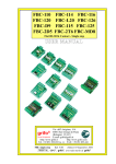
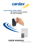
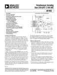
Executive Summary The Cellwatch system is built using modules. The majority of the system is constructed with Data Collection Modules (DCMs). The DCMs are optically linked to Control Units (CUs) that in turn are connected via RS485 to the Battery Monitoring Unit (BMU or iBMU), a rack or wall-mounted PC, running the proprietary Cellwatch software under the Windows operating system. The system architecture is such that a battery monitoring system can easily be configured for any size battery, anywhere, and be added to economically. A single Cellwatch system is also able to monitor switchgear and generator battery sets with the addition of a simple extender kit. Technical Description Cellwatch is a state-of-the-art battery monitoring system designed specifically for large (three-phase) UPS. It utilizes the latest fiber optic technology to provide rapid, noise-free transmission of information on battery health. The modular system continuously monitors the entire battery system, including string and cell level voltage, ohmic value, current and temperature throughout the charge, discharge, and float periods. Cellwatch provides immediate warnings of battery deterioration, including thermal runaway and imminent failure of batteries. Cellwatch identifies any individual battery that exhibits problems—providing a proactive approach to ensuring UPS reliability. In addition, this monitoring system allows battery replacement to be based on the battery’s condition, not simply on how long it’s been in use, helping avoid premature and unnecessary replacement. The concepts behind the Cellwatch system are flexibility, ease of installation, safe use and operation. It can be installed on new or old batteries. The modular design allows the system to fit applications of any size and configuration, including monitoring several separate battery systems simultaneously (UPS, switchgear, generator). Battery parameters which can be monitored on a per cell basis include: • On Float Voltage • Ohmic Value (OV) On a battery system, it can report on: • Total Float Voltage • String Current • Ambient Temperature • Pilot Temperature In Cellwatch, current and temperature monitoring are constant, voltage can be user-defined for every 6 hours or hourly scans and ohmic value can be set for monitoring every 12 or 24 hours. Cellwatch best practices are to set the voltage scan on an hourly basis and ohmic value every 24 hours. The Cellwatch system provides daily battery monitoring with an ultra-light pulsed 1 amp load. It is also the only battery monitoring system that is fully UL listed and CE certified. 130 Seaboard Lane A-13, Franklin, TN 37067 Phone: (615) 661-6261 • Fax (615) 661-6288 www.johntech.com Communication The iBMU is set up to automatically search for and obtain a TCP/IP address from a local network DHCP sever.* If no network DHCP server is available (i.e. when the network is not connected) the iBMU will automatically use 192.168.0.128 as a default address. This is most useful as this address is what is used to connect to the iBMU from a laptop using pcAnywhere. PcAnywhere on the iBMU is configured to launch a ‘host’ which runs automatically and minimized, when Windows starts up. The host ID is ‘cellwatch’ and it is configured to accept connections through the network (Ethernet) or through a modem (note - you cannot connect to the host by network and modem at the same time). The version of pcAnywhere supplied is a single license Remote and Host, so that the Remote element can be installed on the user’s own computer system. *If, for security reasons, a network administrator does not want the Cellwatch iBMU to be installed on the network, then a remote monitoring solution is still available across the network via a KVM-over-IP system (end-user or partner supplied – not a Cellwatch component). This solution allows visibility and control of the iBMU over the network without plugging the network into the iBMU. It simply transmits video, mouse and keyboard signals over the network. KVMSwitchTech.com is a reliable source and the RKD-KVM-17 model is compatible with Cellwatch (http://www.kvmswitchtech.com). WEB SERVER: Cellwatch comes with an integral HTTP web server (secure or open capability). This is turned on from the Cellwatch software screen and allows anyone on the user’s network to see the summarized results from the battery monitoring system. For this to operate, Cellwatch must be connected to a Local Area Network and correctly configured by the network administrator for the monitoring system to be viewed across the Internet. Cellwatch data is refreshed every 10 seconds (by default but modifiable) and can be accessed from a standard web browser anywhere in the world. This access to Cellwatch is read-only and cannot interfere with the operation of Cellwatch battery monitoring. This web server allows only ‘push’ and the download of data, and is only available on port 80. We are not aware of any security issues with this web server. MODEM CONNECTION: As noted previously, the pcAnywhere host is already configured to accept an incoming connection via the internal modem of the iBMU. All that is required to establish a connection is to ensure that the iBMU is connected to a suitable telephone line, and to dial into it from a PC having a pcAnywhere remote set up. MODBUS TCP/IP INTERFACE: The Cellwatch software, running on the iBMU, can communicate with a Modbus device using TCP/IP protocols over a network. The Modbus function is turned on in the Cellwatch software using the dropdown menu and the iBMU must be connected to the same network as the MODBUS device. Cellwatch can transfer more detailed battery and alarm information upon request from another MODBUS-enabled device on the same network. BUILDING MANAGEMENT SYSTEM (BMS) INTERFACE: The simple BMS Gateway allows the Cellwatch software running on its iBMU to interface to a facility’s management and control software package using the iBMU RS232 port. Enabling this function allows the 130 Seaboard Lane A-13, Franklin, TN 37067 Phone: (615) 661-6261 • Fax (615) 661-6288 www.johntech.com software to communicate via the serial port to an external computer system for reporting and further alarm functions. CELLWATCH.NET: An optional web-based service that extends the functionality of Cellwatch battery monitoring by providing email alarm routing, disaster recovery and uptime monitoring. It can use either a network SMTP or a dial-up connection or both (cascaded, network first). It uses its own send-mail program and does not receive emails in any way so should not present a security problem. This product is available separately and renewable for a fee on an annual basis. CELLWATCH EMAIL ALERT: Cellwatch Email Alert is now available as a downloadable feature for the Cellwatch iBMU with software versions 4.0 and higher. With the Cellwatch Email Alert feature, you’ll know instantly when a battery issue arises no matter where you are. The software will allow a Cellwatch administrator to self-configure an email address to receive all alarm events, and notifications can also be sent to an SMSC gateway. System requirements for Windows 7: Cellwatch software versions 4.0 and higher will support the Windows 7 operating system (older versions are not compatible with the Operating System.) Systems shipped after October, 2012 and beyond are fully compatible with the Windows 7 OS, only requiring a new Solid State Hard Drive to facilitate the upgrade. Key advantages of Windows 7 for Cellwatch users are: Microsoft will be providing patches and bug fixes for many years to come. Automatic updates are now available at the administrator’s discretion. This version of Windows 7 Embedded is fully optimized to maximize the performance of the Cellwatch battery monitoring application. All Cellwatch history data is fully compatible and will not be lost during the upgrade process. Upgrading to Windows 7 ensures long-term Cellwatch Operating System Support. Please see www.cellwatch.com/appnotes for installation/user manual and other application notes for Modbus tables, critical distances and configuration parameters. Preventing Thermal Runaway with Cellwatch Will Cellwatch detect and prevent thermal runaway? YES it will if installed and used properly, Cellwatch will detect the symptoms of thermal runaway in cabinetised VRLA batteries and alarm the facility manager/battery technician before significant damage is caused. Thermal runaway is caused by the heat generated in mainly VRLA lead acid cells exceeding their ability to dissipate that heat and can result in complete destruction of the battery including the risk of fire. This can be caused by A charger fault applying too much voltage/current to the battery string 130 Seaboard Lane A-13, Franklin, TN 37067 Phone: (615) 661-6261 • Fax (615) 661-6288 www.johntech.com Weak or shorted cells in a string causing other jars or cells to overcharge Excessive heat being applied to a battery string due to faulty HVAC or poor location Acid leaks or corrosion causing ground faults Excessive AC ripple causing overheating Thermal runaway rarely occurs quickly, it is most often a process that takes place over several days, so can be detected by continuous battery monitoring, provided battery monitoring takes place DAILY. Cellwatch provides dry contact relays in its Control Unit for the triggering of external events such as audible or visual alarms. A dedicated Thermal Runaway switch can be created by following these guidelines: 1. Only use the high voltage alarm limits on the string being protected – follow the rules above, set the low voltage alarms to 50% nominal jar voltage (6v on a 12v system) 2. Only use the high temperature alarm limits on any string on this control unit – follow the rules above, set the low temperature to 1 (either ºC or ºF) 3. Install one Control Unit per UPS battery. Even if you have only one string per UPS. If you have 4 UPS batteries, with 1 string each, install 4 Control Units 4. The Config Builder program will accommodate this configuration by using the “Force” this string to be on a new Control Unit” function 5. Wire the CU relays labelled Voltage and Temperature Normally Open connections in series with the Current relay’s normally closed contact so that when both V and T conditions are met and its not in a discharge the alarm can be triggered. Three alarms generated by Cellwatch are specific to preventing thermal runaway: Ohmic Value Alarms Measurement of ohmic value (internal resistance) on a daily basis is the best predictor of cell failure, and cell failure is one of a number of causes of thermal runaway. Changes in cell characteristics that cause thermal runaway that are detected by ohmic value alarms would include internal plate shorting and premature aging. Voltage Alarms Cellwatch voltage alarm parameters detect overcharging caused by rectifier problems or adjacent cell failure. They will also detect under voltage that may indicative of an overheating cell in the early stages of a charger-caused thermal cycle. Temperature Alarms Mounting Cellwatch temperature probes in the correct locations, at the top of racks or cabinets and on pilot cells will reduce the probability of thermal runaway by detecting when charger faults occur and overcharge all the cells in a battery. Installation The diagram in figure 1 (below) shows a basic layout of the Cellwatch system. Each DCM can read voltage or ohmic value data from four cells, jars or monoblocs. The control unit (CU) incorporates current and temperature inputs, as well as converting the optic signals to RS485. All DCMs are linked fiber optically in a series loop to the CU. One BMU can control up to 31 CUs and each CU can control up to 130 Seaboard Lane A-13, Franklin, TN 37067 Phone: (615) 661-6261 • Fax (615) 661-6288 www.johntech.com 254 Data Collection Modules (DCMs). In addition, each CU has up to 4 current inputs and up to 4 temperature inputs, along with 4 alarms triggered volt-free relay contacts. Electrical Requirements The BMS shall meet the requirements of the National Electrical Code. Each component that connects to the 110vAC to 240vAC utility power and is connected in some way to any part of the system that is humanly accessible shall be UL approved. The BMS shall be designed and manufactured in such a way as to survive; over and under voltage transients of any duration, and over current conditions caused by the primary 110v/240v AC power source. The low voltage components of the BMS connected to the battery shall not draw from the battery being measured, more than 25mA average during any 24 hour period, for the entire battery monitoring system. 130 Seaboard Lane A-13, Franklin, TN 37067 Phone: (615) 661-6261 • Fax (615) 661-6288 www.johntech.com SAFETY The BMS shall be connected to the battery in such a way as to ensure there is no risk of high DC voltage transmission to an operator panel or other human interface. For this requirement high DC voltage shall mean a voltage that is regularly over 60vDC. To avoid the risk of short circuit and / or fire, cables connected to the battery shall be limited to a maximum length of 5 metres (15 feet) and shall be constructed of cable approved to UL1015 of a gauge no less than 22AWG. For safe identification all cables leading to or from the battery shall be clearly identified either with cable markers or by using colour coded cables. All measuring circuits connected to the battery shall be protected by high impedance circuits or fuses to avoid the risk of accidental discharge. No components, cables, cases, displays connected to the battery or forming part of the human interface shall be flammable, nor shall they rise to a temperature that presents a hazard to operators, maintenance technicians or other service personnel. ROI Analysis Purchasing a Cellwatch system will save money in 3 ways: 1. Eliminating the need for purchasing battery PMs on a monthly, quarter, semi-annual, or annual basis. 2. Maintaining the integrity of the batteries in the string by identifying and removing a failing battery when it occurs, therefore, increasing the time between complete battery replacements. 3. Reducing the chance of a power outage by daily reporting of battery health. The graph above reflects the combined savings experienced when PM costs are reduced and battery life is extended. In this example, a data center with 160 jars and Cellwatch installed will save $90K over a 7 year period, compared to quarterly PMs and no battery monitoring system. When compared to monthly 130 Seaboard Lane A-13, Franklin, TN 37067 Phone: (615) 661-6261 • Fax (615) 661-6288 www.johntech.com PMs and no battery monitoring, the savings would be greater than $250K. Larger battery deployments will save millions. The battery configuration in this example consists of 4 strings, each with 40 jars (160 jars). For the first year of this analysis, there is an opportunity to either purchase a replacement battery or to purchase a Cellwatch system. As you can see the savings can be realized immediately. Example: Cellwatch Battery Monitoring Kit Configuration (2 strings in separate battery rooms) Qty (1) iSK-M240: Main Cellwatch Kit for initial battery rack with 240 monitoring points. Intelligent Battery Monitoring Units (iBMU): Wall mountable (see figure 1) or rack mountable (2U high server module) with Cellwatch software and communication software. LAN and modem included, Modbus TCP/IP and integrated web browser are standard. RS232 to RS485 data connector. Control Unit (CU): Converts RS485 signals to optical signals for DCMs. Handles inputs from the current transducer (CT) and temperature transducers (TT). Houses (4) volt-free alarm contacts to allow connection for additional alarm capabilities. Data Collection Modules: A small solid state component that connects to (4) cells to be monitored. Connects to the CU via fiber optic, providing a safe (no voltage) connection with noise immunity. Power to the DCM is supplied from the batteries it is monitoring. Measures voltage and ohmic value (internal resistance) of its host cell. Each channel can be 2, 4, 6 or 12 volts. DCM Accessory Kits: Fiber optic cable, rubber boots, tie mounts, ring tags. Current Transducer (CT): Measures string current for discharge and recharge. Temperature Transducers (TT): Measures pilot cell and ambient battery room temperatures. Qty (1) iSK-CS240: Second Cellwatch Kit for 2nd rack with 240 monitoring points. Same components as above except for the iBMU. Control Unit (CU): Converts RS485 signals to optical signals for DCMs. Handles inputs from the current transducer (CT) and temperature transducers (TT). Houses (4) volt-free alarm contacts to allow connection for 130 Seaboard Lane A-13, Franklin, TN 37067 Phone: (615) 661-6261 • Fax (615) 661-6288 www.johntech.com additional alarm capabilities. Data Collection Modules: A small solid state component that connects to (4) cells to be monitored. Connects to the CU via fiber optic, providing a safe (no voltage) connection with noise immunity. Power to the DCM is supplied from the batteries, it is monitoring. Measures voltage and ohmic value (internal resistance) of its host cell. Each channel can be 2, 4, 6, 12 or 16 volts. DCM Accessory Kits: Fiber optic cable, rubber boots, tie mounts, ring tags. Current Transducer (CT): Measures string current for discharge and recharge. Temperature Transducers (TT): Measures pilot cell and ambient battery room temperatures. 130 Seaboard Lane A-13, Franklin, TN 37067 Phone: (615) 661-6261 • Fax (615) 661-6288 www.johntech.com