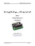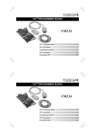
1
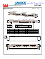
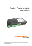
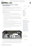
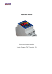
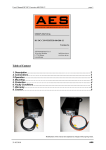
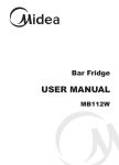
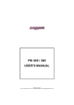
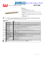
Jameco SKU Number: 2106116
RCP-MU
Power Control and Monitor System
Features :
1U low profile
19-inch rack mounting
Control and monitor up to 3 RCP-1000 units
Suitable for all kinds of RCP output (12V,24V,48V)
Digital meters for output voltage, output current, and internal temperature
on front panel
Potential meter for adjusting output voltage of RCP-1000 unit on front panel
Relay contacts and LED indicators for AC fail, DC fail, and over temperature
warning
Removable fixing accessory
3 years warranty
2
Description : RCP-MU is the monitoring and control unit used for the RCP-1000 series rack power. It can decode the I C signal sent by
RCP series and display through digital meters or relay contact signals. RCP-MU can also turn ON/OFF or trim the output
voltage of RCP-1000 remotely that make the basic control more easily.
SPECIFICATION
MODEL
INPUT
RCP-MU
VOLTAGE RANGE
90 ~ 264VAC
FREQUENCY RANGE
47 ~ 63Hz
AC CURRENT (Typ.)
INRUSH CURRENT (Typ.)
0.35A/115VAC
30A/115VAC
MONITORING INPUTS
DIGITAL METER
OUTPUT
FUNCTION
ENVIRONMENT
CONTROL OUTPUT
127 ~ 370VDC
0.2A/230VAC
50A/230VAC
2
I C signal ( AC OK, DC OK, and over temperature alarm signals for each RCP-1000 unit ), output voltage of the RCP-1U rack
Note.2 Display the DC output voltage, current, and internal temperature of each RCP-1000 unit
Remote ON/OFF and output voltage trimming for each RCP-1000 unit
RELAY CONTACT
Alarm for AC Fail, DC Fail, and Over Temperature ; rating : 30VDC, 1A
LED INDICATOR
AC Fail, DC Fail, Over Temperature
REMOTE ON/OFF CONTROL
The controlled RCP-1000 unit can be turned ON/OFF on the front panel for RCP-MU
VOLTAGE TRIM
Output voltage of the controlled RCP-1000 unit and be trimmed by 10% on the front panel of RCP-MU
WORKING TEMP.
-20 ~ +60
WORKING HUMIDITY
STORAGE TEMP., HUMIDITY
VIBRATION
SAFETY STANDARDS
WITHSTAND VOLTAGE
20~90% RH non-condensing
-40 ~ +85
, 10 ~ 95% RH
10 ~ 500Hz, 2G 10min./1cycle, 60min. each along X, Y, Z axes
Design refer to UL60950-1, TUV EN60950-1
I/P-O/P:3KVAC I/P-FG:1.5KVAC O/P-FG:0.5KVAC
SAFETY & ISOLATION RESISTANCE
I/P-O/P, I/P-FG, O/P-FG:100M Ohms / 500VDC / 25
EMC
EMI CONDUCTION & RADIATION Compliance to EN55022 (CISPR22) Class B
HARMONIC CURRENT
OTHERS
NOTE
Compliance to EN61000-3-2,-3
EMS IMMUNITY
Compliance to EN61000-4-2,3,4,5,6,8,11
DIMENSION
440*68*44mm (L*W*H)
1.15Kg; 6pcs/8Kg/1.27CUFT
PACKING
/ 70% RH
1. All parameters NOT specially mentioned are measured at 230VAC input, rated load and 25 of ambient temperature.
2. Resolution and tolerance of the values shown on the digital meter depends on the controlled RCP series.
File Name:RCP-MU-SPEC 2008-08-07
Jameco SKU Number: 2106116
RCP-MU
Power Control and Monitor System
Mechanical Specification
Case No. 701A
3
DC Fail
Tem p Alar
m
AC Fail
OFF
1
2
3
PSU
ON/O FF
VOL TS
AMP S
DC Fail
Tem p Alar
m
PSU1
2
AC Fail
TEM P
VOL TS
AMP S
DC Fail
Tem p Alar
m
PSU3
AC Fail
ON
1
PSU2
Your Reliab le Power
Partne r
PSU
Output Adjus
t
Unit:mm
TEM P
VOL TS
AMP S
TEM P
BACK
Model Select
Switch
AC Input Terminal Block
Communication
Connector
Output
Voltage Lock
Alarm Signals Terminal Block
Alarm Signals
w w w. m e a n w e l l . c o m
100 - 240VAC
N
L
Temp 3
Alarm
DC 3
Fail
AC 3
Fail
3
5
Temp 2
Alarm
DC 2
Fail
AC 2
Fail
9
11
Temp 1
Alarm
DC 1
Fail
AC 1
Fail
15
17
All alarm signals are potential free relays
1
2
4
6
7
8
10
12
13
14
16
18
2
Pin No.
1
2
3
13
14
25
Disable
1 2 3
3
AC Input Terminal Block
1
Enable
Supply Voltage: 100 - 240VAC 50/60Hz
0.35 - 0.2A
1
Communication
VOLTS
LOCK
MODEL
SELECT
Model : RCP-MU
1 2 3
Alarm Signals Pin No. Assignment
Assignment
FG
AC/N
AC/L
Pin No.
1,2
3,4
5,6
Assignment
Temp 3 Fail
DC 3 Fail
AC 3 Fail
Pin No.
7,8
9,10
11,12
Assignment
Temp 2 Fail
DC 2 Fail
AC 2 Fail
Pin No.
13,14
15,16
17,18
Assignment
Temp 1 Fail
DC 1 Fail
AC 1 Fail
Communication Connector Pin No. Assignment
Pin No.
1
2
3
4
5
Pin No.
Assignment
ON/OFF-A
AC-OK-A
DC-OK-A
V-TRIM-A
T-ALARM-A
Pin No.
Assignment
+5V-AUX
GND-AUX
ON/OFF-B
AC-OK-B
DC-OK-B
6
7
8
9
10
Assignment
V-TRIM-B
T-ALARM-B
NC
CS
ON/OFF-C
11
12
13
14
15
Pin No.
Pin No.
Assignment
AC-OK-C
DC-OK-C
V-TRIM-C
T-ALARM-C
+S
16
17
18
19
20
Assignment
-S
+V
SCL
SDA
-V
21
22
23
24
25
68
TOP
AMPS
ON
PSU
Output Adjust
1
2
3
PSU
ON/OFF
OFF
1
2
AC Fail
DC Fail
VOLTS
AMPS
Temp Alarm
TEMP
AC Fail
DC Fail
VOLTS
AMPS
Temp Alarm
TEMP
3
Remote Adjust Remote ON/OFF
Display of PSU1
Display of PSU2
TEMP
7.4
36.9
VOLTS
Temp Alarm
PSU3
DC Fail
PSU2
AC Fail
Partn er
Your Relia ble Power
10.2
PSU1
44
7.1
FRONT
Display of PSU3
440
466.1
483.6
File Name:RCP-MU-SPEC 2008-08-07
Jameco SKU Number: 2106116
RCP-MU
Power Control and Monitor System
Block Diagram
The diagram below only shows one set of input / output signals. One RCP-MU can control and monitor up to 3 units of RCP-1000 power unit.
PSU ON/OFF
ON / OFF
Display
Voltage
Current
Temperature
LED Alarm
AC Fail
DC Fail
Temp Alarm
PSU
Output Adjust
+V
MCU
V- Trim
-V
AC Fail
Relay
Contact
SCA / SDL
DC Fail
Temp Alarm
12V
24V
48V
66V
Model
Select
Typical User Manual
RCP-1U Address dip switch setting
1. Monitoring Input
RCP-1U
ON
RCP-MU
Communication
CN500
OFF
1 2 3 4 5 6 7 8 9
Module A Module B Module C
2. Alarm Signal Relay Contact
Function
Description
AC Fail
When input AC fail, relay open, LED lights
DC Fail
When output DC fail, relay open, LED lights
Temp Alarm
When temperature exceed the limit of temperature, relay open, LED lights
3. Model Select Switch
To get better display resolution, the correct output voltage of RCP-1000 that is monitored should be chosen. The factory original setting is for 48V models.
ON
1 2 3
OFF
ON
ON
(24V)
(12V)
(48V)
1 2 3
OFF
1 2 3
OFF
ON
(66V)
1 2 3
OFF
(For special custom made
RCP-1000 models)
4. Output Voltage Lock
The output voltage adjustment for RCP-1000 units can be enabled or disabled for different application needs.
Enable
Voltage of power device can not be adjusted.
(a)
1 2 3
Disable
Enable
Voltage of power device can be adjusted independently by VRs.
(b)
1 2 3
Disable
File Name:RCP-MU-SPEC 2008-08-07
RCP-MU
Power Control and Monitor System
INPUT FUNCTION TEST
NO
1
TEST ITEM
SPECIFICATION
TEST CONDITION
INPUT VOLTAGE RANGE
90VAC~264 VAC
I/P:TESTING
RESULT
VERDICT
25 V~264V
O/P:RCP-1000 UNIT
Ta:25℃
I/P:
TEST: OK
LOW-LINE-3V= 87 V
P
HIGH-LINE+15%=300 V
O/P: RCP-1000 UNIT
ON: 30 Sec . OFF: 30 Sec 10MIN
( AC POWER ON/OFF NO DAMAGE )
2
INPUT FREQUENCY RANGE
47HZ ~63 HZ
I/P: 90VAC ~ 264 VAC
NO DAMAGE OSC
TEST: OK
O/P: RCP-1000 UNIT
P
Ta:25℃
5
INPUT CURRENT
230V/
0.2
A (TYP)
I/P: 230 VAC
I=
0.04
A/ 230 VAC
115V/
0.35
A (TYP)
I/P: 115 VAC
I=
0.048
A/ 115 VAC
P
O/P: RCP-1000 UNIT
Ta:25℃
6
INRUSH CURRENT
230V/
50
A (TYP)
I/P: 230 VAC
I=
30
A/ 230 VAC
115V/
30
A(TYP)
I/P: 115 VAC
I=
15
A/ 115 VAC
COLD START
P
O/P: RCP-1000 UNIT
Ta:25℃
CONTROL FUNCTION TEST
NO
1
2
TEST ITEM
SPECIFICATION
TEST CONDITION
RESULT
REMOTE CONTROL
The controlled RCP-1000 unit
I/P: 230 VAC
OK
can be turned ON/OFF on the
O/P: RCP-1000 UNIT
front panel for RCP-MU
Ta:25℃
Output voltage of the controlled
I/P: 230 VAC
12V=10.1
V~13.6
V
RCP-1000 unit and be trimmed
O/P: RCP-1000 UNIT
24V=18.5
V~26.7
V
by 10% on the front panel of
Ta:25℃
48V=38.3
V~53.6
V
66V=53.6
V~73.3
V
VOLTAGE TRIM
RCP-MU
VERDICT
p
Model: RCP-MU
p
Test Report
1 / 7
RCP-MU
Power Control and Monitor System
TYPICAL USER MANUAL
NO
1
TEST ITEM
Monitoring Input
SPECIFICATION
TEST CONDITION
RESULT
RCP-1U Address dip switch
I/P: 230 VAC
OK
setting
O/P: RCP-1000 UNIT
VERDICT
Ta:25℃
P
2
Alarm
Signal
Relays Contact
3
I/P: 230 VAC
OK
Function
Description
O/P: RCP-1000 UNIT
AC Fail
When input AC fail, relay
open, LED lights
Ta:25℃
DC Fail
When output DC fail, relay
open, LED lights
Temp Trip
When temperature exceed
the limit of temperature,
relay open, LED lights
P
Mode Select
To get better display resolution, the correct output voltage of RCP-1000 that is
I/P: 230 VAC
Switch
monitored should be chosen. The factory original setting is for 48V models.
O/P: RCP-1000 UNIT
OK
Ta:25℃
P
4
Voltage Adjust
Power device voltage can not be adjusted.
I/P: 230 VAC
OK
O/P: RCP-1000 UNIT
Ta:25℃
P
Power device voltage can be adjust independently by VRs.
Model: RCP-MU
Test Report
2 / 7
RCP-MU
Power Control and Monitor System
7 Segment Display - LED / Relay TEST:
Normal condition :
TEST CONDITION
PSU AC IN OFF
PSU AC IN ON
RESULT
PSU SWITCH OFF
Ok
PSU SWITCH ON
Ok
Abnormal condition
TEST CONDITION
OTP
Output Shorting
RESULT
PSU SWITCH ON
ok
&
PSU AC IN ON
Note:
○
LED DARK:OK
LED LIGHTS : FAIL
:Relay short
:Relay open
Model: RCP-MU
Test Report
3 / 7
RCP-MU
Power Control and Monitor System
DIGITAL METER TEST:
TEST CONDITION:INPUT VOLTAGE:230VAC
POWER
UNIT
Module
A
RCP-1000-12
B
C
A
RCP-1000-24
B
C
A
RCP-1000-48
B
C
A
RCP-1000-66
B
C
TEST
CONDITION
output voltage
on the display
DMM voltage
measurement
output current
on the display
DMM current
measurement
internal
temperature on
the display
Digital
thermometer
measurement
VERDICT
NO LOAD
12.1V
12.07V
0A
0A
35.5℃
35.7℃
OK
50% LOAD
12.3V
12.06V
29.8A
30.7A
35.5℃
35.8℃
OK
100% LOAD
12.5V
12.05V
60.1A
61.6A
34.8℃
35.3℃
OK
NO LOAD
12.1V
12.07V
0A
0A
31℃
30.9℃
OK
50% LOAD
12.4V
12.06V
29.8A
30.6A
30.6℃
30.7℃
OK
100% LOAD
12.5V
12.05V
60.1A
61.5A
29.9℃
29.8℃
OK
NO LOAD
12.1V
12.07V
0A
0A
28.7℃
28.7℃
OK
50% LOAD
12.4V
12.06V
29.8A
30.6A
29.1℃
29.4℃
OK
100% LOAD
12.5V
12.05V
60.1A
61.4A
31.4℃
30.3℃
OK
NO LOAD
23.9V
24.11V
0A
0A
35.9℃
35.3℃
OK
50% LOAD
24.2V
24.11V
19.8A
20.3A
36.3℃
35.5℃
OK
100% LOAD
24.2V
24.1V
40.5A
40.9A
36.7℃
35.8℃
OK
NO LOAD
23.9V
24.11V
0A
0A
27.6℃
27.7℃
OK
50% LOAD
24.1V
24.11V
19.6A
20.3A
28℃
28.1℃
OK
100% LOAD
24.2V
24.11V
40.5A
40.7A
30.6℃
30.7℃
OK
NO LOAD
23.9V
24.12V
0A
0A
32.5℃
31.7℃
OK
50% LOAD
24.2V
24.11V
19.8A
20.2A
32.1℃
31.4℃
OK
100% LOAD
24.2V
24.11V
40.5A
40.7A
31.4℃
30.3℃
OK
NO LOAD
47.8V
48.2V
0A
0A
34.8℃
34.9℃
OK
50% LOAD
48.1V
48.19V
10.3A
10.7A
34.8℃
34.9℃
OK
100% LOAD
47.8V-48.3V
48.18V
20.8A
21.6A
34.8℃
34.8℃
OK
NO LOAD
48.1V
48.13V
0A
0A
31.8℃
32.9℃
OK
50% LOAD
48.3V
48.13V
10.2A
10.7A
32.1℃
32.6℃
OK
100% LOAD
48.3V-48.6V
48.12V
20.7A
21.6A
32.1℃
32.7℃
OK
NO LOAD
47.8V
48.13V
0A
0A
31.4℃
32.4℃
OK
50% LOAD
48.1V
48.13V
10.3A
10.8A
31.4℃
32.3℃
OK
100% LOAD
47.8V-48.3V
48.12V
20.6A
21.6A
30.2℃
31.8℃
OK
NO LOAD
65.6V
66.14V
0A
0A
31.4℃
31.9℃
OK
50% LOAD
65.6V
66.14V
7.8A
7.5A
30.1℃
31.5℃
OK
100% LOAD
65.6V-65.9V
66.14V
15.2A
15.3A
30.2℃
30.6℃
OK
NO LOAD
65.6V
66.16V
0A
0A
29.9℃
29℃
OK
50% LOAD
65.6V
66.16V
7.8A
7.5A
30.2℃
29.4℃
OK
100% LOAD
65.6V-65.9V
66.15V
15.2A
15.3A
31.8℃
30.9℃
OK
NO LOAD
65.6V
66.17V
0A
0A
33.3℃
33.3℃
OK
50% LOAD
65.6V
66.16V
7.8A
7.6A
32.9℃
32.5℃
OK
100% LOAD
65.6V-65.9V
66.15V
15.2A
15.4A
33.3℃
33℃
OK
NOTE: output voltage/ current /internal temperature on the display. For tolerance range, please refer to specification of RCP-1000.
Model: RCP-MU
Test Report
4 / 7
RCP-MU
Power Control and Monitor System
ENVIRONMENT TEST
NO
1
TEST ITEM
SPECIFICATION
TEST CONDITION
TEMPERATURE RISE TEST
MODEL:RCP-MU
RESULT
VERDICT
1. HIGH AMBIENT BURN-IN:2.5 HRS
I/P: 230VAC O/P: RCP-1000-48*3PCS
2
LOW TEMPERATURE
Ta= 61 ℃
HIGH AMBIENT
NO
Position
P/N
1
2
U101
U7
HEF4511B
74HC573D
3
U5
PIC18F4321-I/PT
63.7℃
4
U6
74HC573D
59.8℃
5
U4
74HC573D
58.4℃
6
U3
74HC573D
58.9℃
7
Q2
TIP122 5A/100V
67.8℃
8
C7
100u/25V UL10Kh YXM
65.0℃
9
LF1
LF501
60.9℃
10
T1 COIL
TF-1394
72.4℃
11
U1
FSDM0265RNB
76.6℃
12
C105
220U/35V 105℃ KY
67.0℃
13
RY3
RELAY OUAZ-SS-112L
72.4℃
14
RY4
RELAY OUAZ-SS-112L
71.5℃
15
RY5
RELAY OUAZ-SS-112L
69.3℃
TURN ON AFTER
2 HOUR
TURN ON TEST
Ta= 61 ℃
60.3℃
62.0℃
P
TEST:OK
I/P: 230 VAC
O/P: RCP-1000-48*3PCS
P
Ta= -20 ℃
3
4
TEST:OK
HIGH HUMIDITY
AFTER 12 HOURS
I/P: 272 VAC
HIGH TEMPERATURE
IN CHAMBER ON
O/P: RCP-1000-48*3PCS
HIGH VOLTAGE
CONTROL 60 ℃
Ta= 60 ℃
TURN ON TEST
NO DAMAGE
HUMIDITY=
VIBRATION TEST
1 Carton & 1 Set
P
95 %R.H
TEST:OK
(1) Waveform: Sine Wave
(2) Frequency:10~500Hz
(3) Sweep Time:10min/sweep cycle
(4) Acceleration:2G
P
(5) Test Time:1 hour in each axis (X.Y.Z)
(6) Ta:25℃
Model: RCP-MU
Test Report
5 / 7
RCP-MU
Power Control and Monitor System
SAFETY TEST
NO
1
TEST ITEM
SPECIFICATION
TEST CONDITION
WITHSTAND VOLTAGE
I/P-O/P: 3 KVAC/min
I/P-O/P: 3.6 KVAC/min
I/P-O/P:
1.26
mA
I/P-FG: 1.5 KVAC/min
I/P-FG: 1.8 KVAC/min
I/P-FG:
0.85
mA
O/P-FG: 0.5 KVAC/min
O/P-FG: 0.6 KVAC/min
O/P-FG:
3.41
mA
Ta:25℃
2
ISOLATION RESISTANCE
GROUNDING CONTINUITY
I/P-O/P:500VDC>100MΩ
I/P-O/P: 500
I/P-FG: 500VDC>100MΩ
I/P-FG:
O/P-FG:500VDC>100MΩ
O/P-FG: 500
VDC
I/P-O/P:
1.5
GΩ
500 VDC
I/P-FG:
1.1
GΩ
O/P-FG:
7.4
GΩ
VDC
P
P
NO DAMAGE
FG(PE) TO CHASSIS
40 A / 2min
OR TRACE <
Ta:25℃ / 70%RH
100 mΩ
VERDICT
NO DAMAGE
Ta:25℃/70%RH
3
RESULT
18
mΩ
P
E.M.C TEST
NO
TEST ITEM
SPECIFICATION
TEST CONDITION
RESULT
1
HARMONIC
EN61000-3-2
I/P: 230 VAC/50HZ
PASS
CLASS A
O/P:FULL LOAD
VERDICT
P
Ta:25℃
2
CONDUCTION
EN55022
I/P: 230 VAC (50HZ)
PASS
CLASS B
O/P:FULL LOAD
Test by certified Lab
P
Ta:25℃
3
RADIATION
EN55022
I/P: 230 VAC (50HZ)
PASS
CLASS B
O/P:FULL LOAD
Test by certified Lab
P
Ta:25℃
4
5
6
E.S.D
E.F.T
SURGE
EN61000-4-2
I/P: 230 VAC/50HZ
LIGHT INDUSTRY
O/P:FULL LOAD
AIR:8KV / Contact:4KV
Ta:25℃
EN61000-4-4
I/P: 230 VAC/50HZ
LIGHT INDUSTRY
O/P:FULL LOAD
INPUT: 1KV
Ta:25℃
IEC61000-4-5
I/P: 230 VAC/50HZ
LIGHT INDUSTRY
O/P:FULL LOAD
L-N :1KV
CRITERIA A
P
CRITERIA A
P
CRITERIA A
P
Ta:25℃
L,N-PE:2KV
7
Test by certified Lab & Test Report Prepare
M.T.B.F & LIFE CYCLE CALCULATION
NO
TEST ITEM
SPECIFICATION
TEST CONDITION
RESULT
1
CAPACITOR
SUPPOSE C105
LIFE CYCLE
I/P: 230VAC
O/P: RCP-1000-48*3PCS Ta= 25 ℃
LIFE TIME= 1182279 HRS
I/P: 230VAC
O/P: RCP-1000-48*3PCS Ta= 60 ℃
LIFE TIME= 104510 HRS
VERDICT
IS THE MOST CRITICAL COMPONENT
P
COMPONENT STRESS TEST
NO
1
TEST ITEM
SPECIFICATION
TEST CONDITION
RESULT
Power Transistor
Q2 Rated
I/P:High-Line +3V = 267 V
(1)
( D to S) or (C to E) Peak Voltage
TIP122 : 100V 5A
O/P: (1) RCP-1000 UNIT
VERDICT
7.7
V
P
Ta:25℃
Model: RCP-MU
Test Report
6 / 7
RCP-MU
Power Control and Monitor System
DATE
SAMPLE
TEST RESULT
TESTER
APPROVAL
2008/4/18
RD SAMPLE
PASS
SANFORD SU
VINCENT TSENG
PASS
SANFORD SU
VINCENT TSENG
PASS
SANFORD SU
VINCENT TSENG
2008/7/15
2008/8/15
PRODUCT SAMPLE
W0806A33
PRODUCT SAMPLE
W0807D48
2003/12/12 A50-F023
Model: RCP-MU
Test Report
7 / 7