1
DevKit8000 User Manual
Version 1.0
Release: 2009-05-18
DevKit8000 user manual
Revision history
Rev
Date
Description
1.0
2009-01-16
Initial version
For additional information, please visit: http://www.timll.com
DevKit8000
User manual
Timll Technic Inc..
Version 1.0 — 5/19/2009
2 of 71
DevKit8000 user manual
table of contents
DEVKIT8000 USER MANUAL........................................................................................................................ 1
CHAPTER ONE: OVERVIEW........................................................................................................................ 5
I SYSTEM OVERVIEW ........................................................................................................................................ 5
1.1 Introduction ............................................................................................................................................ 5
1.2 Define ..................................................................................................................................................... 6
1.3 Accessories.......................................................................................................................................... 6
CHAPTER TWO: HARDWARE SYSTEM .................................................................................................... 7
II HARDWARE OVERVIEW ................................................................................................................................. 7
2.1 Architecture diagram.............................................................................................................................. 7
2.2 Features.................................................................................................................................................. 8
2.3 Hardware interface diagram .................................................................................................................. 9
III HARDWARE SPECIFICATION ........................................................................................................................ 10
3.1 Power input interface ........................................................................................................................... 10
3.2 Power output interface ......................................................................................................................... 10
3.3 Power switch ........................................................................................................................................ 10
3.4 S-VIDEO interface ................................................................................................................................11
3.5 HDMI Interface .....................................................................................................................................11
3.6 TFT_LCD interface .............................................................................................................................. 12
3.7 AUDIO OUT interface ......................................................................................................................... 13
3.8 Camera interface.................................................................................................................................. 13
3.9 MIC IN interface .................................................................................................................................. 14
3.10 Keyboard interface ............................................................................................................................. 15
3.11 Series ports ......................................................................................................................................... 15
3.12 LAN interface ..................................................................................................................................... 15
3.13 USB OTG interface ............................................................................................................................ 16
3.14 USB HOST interface .......................................................................................................................... 16
3.15 SD/MMC Card interface .................................................................................................................... 17
3.16 JTAG interface.................................................................................................................................... 17
3.17 Expansion interface............................................................................................................................ 18
3.18 KEY .................................................................................................................................................... 19
3.19 LED .................................................................................................................................................... 19
CHAPTER THREE: LINUX SYSTEM......................................................................................................... 21
IV LINUX SYSTEM OVERVIEW ........................................................................................................................ 21
4.1 Pre-installed software ....................................................................................................................... 21
4.2 BSP features...................................................................................................................................... 22
V LINUX SYSTEM QUICK START....................................................................................................................... 23
5.1 system boot ........................................................................................................................................... 23
5.2 choose the display device ..................................................................................................................... 23
5.3 Test........................................................................................................................................................ 24
DevKit8000
User manual
Timll Technology Inc..
Version 1.0 - 5/19/2009
3 of 71
DevKit8000 user manual
5.4 DevKit8000 Demo ................................................................................................................................ 29
VI LINUX SYSTEM DEVELOPMENT ................................................................................................................. 32
6.1 Install the cross compilation environment............................................................................................ 32
6.2 system complie.................................................................................................................................. 33
6.3 System Customization...................................................................................................................... 35
VII LINUX IMAGE UPDATE .............................................................................................................................. 39
7.1 Update the image for SD card.............................................................................................................. 39
7.2 Update the image for NAND Flash ...................................................................................................... 40
VIII THE DEVELOPMENT OF APPLICATION....................................................................................................... 43
8.1 LED application development ......................................................................................................... 43
CHAPTER FOUR: WINCE SYSTEM .......................................................................................................... 45
IX WINCE SYSTEM OVERVIEW ....................................................................................................................... 45
9.1 Pre-compiled image.............................................................................................................................. 45
9.2 Board Support Package(BSP) .............................................................................................................. 46
X WINCE SYSTEM QUICK START ..................................................................................................................... 48
10.1 system boot ......................................................................................................................................... 48
10.2 Test...................................................................................................................................................... 48
XI LINUX SYSTEM DEVELOPMENT ................................................................................................................. 50
11.1 Install the cross compilation environment .......................................................................................... 50
11.2 system complie.................................................................................................................................... 50
XII WINCE IMAGE UPDATE ............................................................................................................................. 54
12.1 Update the image for SD card............................................................................................................ 54
12.2 Update the image for NAND Flash .................................................................................................... 54
XIII THE DEVELOPMENT OF APPLICATION....................................................................................................... 55
13.1 The interface and demonstration of application................................................................................. 55
13.2 The development demonstration of interface application .................................................................. 57
APPENDIX ....................................................................................................................................................... 58
APPENDIX I DRIVER INSTALLATION OF LINUX USB ETHERNET/RNDIS GADGET .......................................... 58
APPENDIX II LINUX BOOT DISK FORMAT ....................................................................................................... 61
APPENDIX III THE SETUP OF TFTP SERVER ...................................................................................................... 66
APPENDIX IV WINCE SOURCE ........................................................................................................................ 68
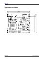
APPENDIX V DIMENSIONS .............................................................................................................................. 69
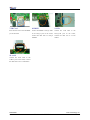
APPENDIX VI PERIPHERAL CONNECTION ........................................................................................................ 70
DevKit8000
User manual
Timll Technology Inc..
Version 1.0 - 5/19/2009
4 of 71
DevKit8000 user manual
Chapter one: Overview
I System Overview
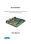
1.1 Introduction
DevKit8000 is an evaluation kit issued by Timll Technic Inc. (Timll) based on processor OMAP35x of
Texas Instrument (TI). Processor OMAP35x is integrated with 600MHz ARM Cortex™-A8 core and
412MHz DSP core which can process and calculate the digital signals. Multiple interfaces are
provided too. DevKit8000 provides network port, S-VIDEO interface, Audio input and output interface,
USB OTG, USB HOST, SD/MMC interface, series port, SPI interface, IIC interface, JTAG interface,
CAMERA interface, TFT interface, interface for touch screen and keyboard, bus interface as well as
HDMI interface.
DevKit8000 has provided a completed software development platform for developers to evaluate
processor OMAP35x. It supports linux-2.6.28 operating system and contains completed basic drivers
in order to provide users a quick way to assess the processor OMAP35x, design drivers for Linux
system and customize application software. Moreover, the release version of the mature operating
system google android and angstrom (GPE), and the DVI output reaches the display standard of
720P, letting users experience the powerful data processing and calculation of processor OMAP35x.
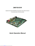
Fig 1.1 Product photo
DevKit8000
User manual
Timll Technology Inc..
Version 1.0 - 5/19/2009
5 of 71
DevKit8000 user manual
1.2 Define
HDMI
DVI
: High Definition Multimedia Interface
: Digital Visual Interface
1.3 Accessories
DevKit8000 Evaluation Kit contains:
z One DevKit8000 Evaluation board
z One 4.3” LCD( contain touch panel)
z One SD card
z One serial cable(IDC10-to-DB9)
z One 5V@2A Power adapter
z One Touch Pen
z One USB cable(Type A Male to Type Mini-B Male)
z One USB cable(Type A Female to Type Mini-A Male)
z One USB HUB
z One cross Ethernet cable
z One HDMI to DVI-D cable
z One S-Video cable
DevKit8000
User manual
Timll Technology Inc..
Version 1.0 - 5/19/2009
6 of 71
DevKit8000 user manual
Chapter Two: Hardware system
II Hardware Overview
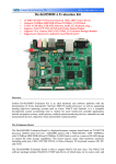
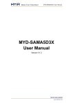
2.1 Architecture diagram
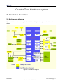
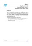
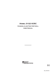
Figure 2.1 is the architecture map for DevKit8000 and Peripheral equipment of this board is also
shown.
Figure 2.1 Architecture diagram
DevKit8000
User manual
Timll Technology Inc..
Version 1.0 - 5/19/2009
7 of 71
DevKit8000 user manual
2.2 Features
The DevKit8000 Evaluation board is based on OMAP3530 processor and takes full features of the
processor. This board is characterized as follows:
Processor
•
OMAP3530 processor (pin-to-pin compatible with OMAP35x families)
•
600-MHz ARM Cortex™-A8 Core
•
412-MHz TMS320C64x+™ DSP Core
•
Integrated L1 memory for ARM CPU (16kB I-Cache, 16kB D-Cache, 256kB L2) and On-Chip
memory (64kB SRAM, 112kB ROM)
Memory
•
128MByte DDR SDRAM, 166MHz
•
128MByte NAND Flash, 16bit
•
Audio/Video Interfaces
•
A 4 line S-VIDEO interface
•
An HDMI interface (High Definition Multimedia Interface)
•
A audio input interface
•
A two-channel audio output interface
LCD/Touch screen
•
Resolution: 480 (W) x 272 (H) dots
•
RGB, 391680 colors
•
Brightness: Typical 350 cd/m2 (min 300 cd/m2)
•
4 line Touch Screen
Data Transfer Interface
•
Serial port:
1 x 3 line serial port, RS232 voltage
1 x 5 line serial port, TTL voltage
•
USB port:
1 x USB2.0 OTG, High-speed, 480Mbps
•
SD/MMC port:
1 channel SD/MMC port, support 3.3V and 1.8V logic voltage
1 channel SD/MMC port, support 1.8V logic voltage
•
Ethernet: 10/100Mbps, RJ45 connector
•
1 channel McSPI Interface (Multichannel Serial Port Interface)
•
1 channel McBSP interface (Multi-Channel Buffered Serial Port)
•
1 channel I2C interface
•
1 channel HDQ interface (HDQ/1-Wire)
Input Interface
•
1 Camera interface (support CCD or CMOS camera)
•
6*6 keyboard interface
•
One 14-pin JTAG interface
•
One BOOT button
•
One RESET button
•
One USER button
DevKit8000
User manual
Timll Technology Inc..
Version 1.0 - 5/19/2009
8 of 71
DevKit8000 user manual
•
One ON/OFF button
Mechanical Parameters
•
Dimensions: 110 mm x 95 mm
•
Input Voltage: +5V
•
Power Consumption: 0.5A @ 5V
•
Temperature Range: 0 `C ~ 70 `C
•
Humidity Range: 20% ~ 90%
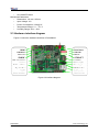
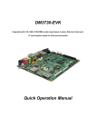
2.3 Hardware interface diagram
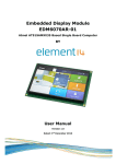
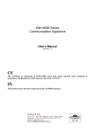
Figure 2.2 show the hardware interface of DevKit8000.
Figure 2.2 interface diagram
DevKit8000
User manual
Timll Technology Inc..
Version 1.0 - 5/19/2009
9 of 71
DevKit8000 user manual
III Hardware specification
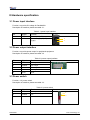
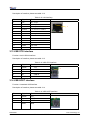
3.1 Power input interface
Function: to provide 5V voltage for DevKit8000.
Description of interface: please see table 3-1.
Table 3-1 power input interface
Pin
Signal
Function
Pin out
1
GND
Power input (+5V)
2
+5V
Power
(Type)
supply
(+5V)
2
2A
1
3.2 Power output interface
Function: to provide power output for peripheral equipment.
Description of interface: please see table 3-2
Table 3-2 power output interface
Pin
Signal
Function
1
VDD50
5V output
2
VDD42
4.2V output
3
VDD33
3.3V output
4
ADCIN
ADC input
5
GND
GND
Pin out
1
3.3 Power switch
Function: +5V power switch
Description of interface: please see table 3-3.
Table 3-3 power switch
Pin
Signal
Function
1
DC IN
VDD Input
2
VDD50
+5V
3
NC
NC
DevKit8000
User manual
Pin out
1
2
Timll Technology Inc..
Version 1.0 - 5/19/2009
10 of 71
DevKit8000 user manual
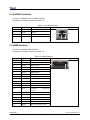
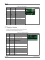
3.4 S-VIDEO interface
Function: A standard 4-line S-VIDEO interface.
Description of interface: please see table 3-4.
Table 3-4 S-VIDEO interface
Pin
Signal
Function
1
GND
GND
2
GND
GND
3
OUTPUT1
VIDEO Y
4
OUTPUT2
VIDEO C
Pin out
4
3
2
1
3.5 HDMI Interface
Function: a standard HDMI interface.
Description of interface: please see table 3-5
Table 3-5 HDMI interface
Pin
Signal
Function
Pin out
1
DAT2+
TMDS data 2+
2
DAT2_S
TMDS data 2 shield
3
DAT2-
TMDS data 2-
4
DAT1+
TMDS data 1+
5
DAT1_S
TMDS data 1 shield
6
DAT1-
TMDS data 1-
7
DAT0+
TMDS data 0+
8
DAT0_S
TMDS data 0 shield
9
DAT0-
TMDS data 0-
10
CLK+
TMDS data clock+
11
CLK_S
TMDS data clock shield
12
CLK-
TMDS data clock-
13
CEC
Consumer
Control
14
NC
NC
15
SCL
IIC master serial clock
16
SDA
IIC serial bidirectional data
17
GND
GND
18
5V
5V
19
HPLG
Hot plug and play detect
Electronics
DevKit8000
User manual
1
Timll Technology Inc..
Version 1.0 - 5/19/2009
11 of 71
DevKit8000 user manual
3.6 TFT_LCD interface
Function: TFT_LCD interface
Description of interface: please see table 3-6
Table 3-6 TFT_LCD interface
Pin
Signal
Function
Pin out
1
DSS_D0
LCD Pixel data bit 0
2
DSS_D1
LCD Pixel data bit 1
3
DSS_D2
LCD Pixel data bit 2
4
DSS_D3
LCD Pixel data bit 3
5
DSS_D4
LCD Pixel data bit 4
6
DSS_D5
LCD Pixel data bit 5
7
DSS_D6
LCD Pixel data bit 6
8
DSS_D7
LCD Pixel data bit 7
9
GND
GND
10
DSS_D8
LCD Pixel data bit 8
11
DSS_D9
LCD Pixel data bit 9
12
DSS_D10
LCD Pixel data bit 10
13
DSS_D11
LCD Pixel data bit 11
14
DSS_D12
LCD Pixel data bit 12
15
DSS_D13
LCD Pixel data bit 13
16
DSS_D 14
LCD Pixel data bit 14
17
DSS_D15
LCD Pixel data bit 15
18
GND
GND
19
DSS_D16
LCD Pixel data bit 16
20
DSS_D17
LCD Pixel data bit 17
21
DSS_D18
LCD Pixel data bit 18
22
DSS_D19
LCD Pixel data bit 19
23
DSS_D20
LCD Pixel data bit 20
24
DSS_D21
LCD Pixel data bit 21
25
DSS_D22
LCD Pixel data bit 22
26
DSS_D23
LCD Pixel data bit 23
27
GND
GND
28
DEN
AC bias control (STN)
or pixel data enable
(TFT)
29
HSYNC
LCD
Horizontal
Synchronization
30
VSYNC
LCD
Vertical
Synchronization
31
GND
GND
DevKit8000
User manual
1
Timll Technology Inc..
Version 1.0 - 5/19/2009
12 of 71
DevKit8000 user manual
32
CLK
LCD Pixel Clock
33
GND
GND
34
X+
X+ Position Input
35
X-
X- Position Input
36
Y+
Y+ Position Input
37
Y-
Y- Position Input
38
SPI_CLK
SPI clock
39
SPI_MOSI
Slave data in, master
data out
40
SPI_MISO
Slave data out, master
data in
41
SPI_CS
SPI enable
42
IIC_CLK
IIC master serial clock
43
IIC_SDA
IIC serial bidirectional
data
44
GND
GND
45
VDD18
1.8V
46
VDD33
3.3V
47
VDD50
5V
48
VDD50
5V
49
RESET
Reset
50
PWREN
Power on enable
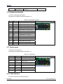
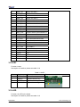
3.7 AUDIO OUT interface
Function: A standard Audio out interface.
Description of interface: please see table 3-7
Table 3-7 Audio out interface
Pin
Signal
Function
1
GND
GND
2
NC
NC
3
Right
Right output
4
NC
NC
5
Left
Left output
Pin out
3.8 Camera interface
Function: Camera image sensor interface
Description of interface: please see table 3-8
DevKit8000
User manual
Timll Technology Inc..
Version 1.0 - 5/19/2009
13 of 71
DevKit8000 user manual
Table 3-8 camera interface
Pin
Signal
Function
1
GND
GND
2
D0
Digital image data bit 0
3
D1
Digital image data bit 1
4
D2
Digital image data bit 2
5
D3
Digital image data bit 3
6
D4
Digital image data bit 4
7
D5
Digital image data bit 5
8
D6
Digital image data bit 6
9
D7
Digital image data bit 7
10
D8
Digital image data bit 8
11
D9
Digital image data bit 9
12
D10
Digital image data bit 10
13
D11
Digital image data bit 11
14
GND
GND
15
PCLK
Pixel clock
16
GND
GND
17
HS
Horizontal synchronization
18
VDD50
5V
19
VS
Vertical synchronization
20
VDD33
3.3V
21
XCLKA
Clock output a
22
XCLKB
Clock output b
23
GND
GND
24
FLD
Field identification
25
WEN
Write Enable
26
STROBE
Flash strobe control signal
27
SDA
IIC master serial clock
28
SCL
IIC serial bidirectional data
29
GND
GND
30
VDD18
1.8V
Pin out
1
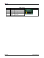
3.9 MIC IN interface
Function: A standard MIC IN interface
Description of interface: please see table 3-9
Table 3-9 MIC IN interface
Pin
Signal
Function
1
GND
GND
2
NC
NC
3
MIC MAIN P
Right input
4
NC
NC
DevKit8000
User manual
Pin out
Timll Technology Inc..
Version 1.0 - 5/19/2009
14 of 71
DevKit8000 user manual
5
MIC MAIN N
Left input
3.10 Keyboard interface
Function: 6X6 keyboard interface
Description of interface: please see table 3-10
Table 3-10 keyboard interface
Pin
Signal
Function
Pin out
1
KC0
Keypad matrix column 0 output
2
KR0
Keypad matrix row 0 input
3
KC1
Keypad matrix column 1 output
4
KR1
Keypad matrix row 1 input
5
KC2
Keypad matrix column 2 output
6
KR2
Keypad matrix row 2 input
7
KC3
Keypad matrix column 3 output
8
KR3
Keypad matrix row 3 input
9
KC4
Keypad matrix column 4 output
10
KR4
Keypad matrix row 4 input
11
KC5
Keypad matrix column 5 output
12
KR5
Keypad matrix row 5 input
13
VDD18
1.8V
14
GND
GND
1
2
3.11 Series ports
Function 3-line series port
Description of interface: please see table 3-11
Table 3-11 series port
Pin
Signal
Function
1
NC
NC
2
TXD
Transit data
3
RXD
Receive data
4
NC
NC
5
GND
GND
6
NC
NC
7
NC
NC
8
NC
NC
9
NC
NC
Pin out
1
PIN 1
6
3.12 LAN interface
Function: to provide a network interface.
DevKit8000
User manual
Timll Technology Inc..
Version 1.0 - 5/19/2009
15 of 71
DevKit8000 user manual
Description of interface: please see table 3-12.
Table 3-12 LAN interface
Pin
Signal
Function
1
TX+
TX+ output
2
TX-
TX- output
3
RX+
RX+ input
4
VDD25
2.5V Power for TX/RX
5
VDD25
2.5V Power for TX/RX
6
RX-
RX- input
7
NC
NC
8
NC
NC
9
VDD
3.3V Power for LED
10
LED1
Speed LED
11
LED2
Link LED
12
VDD
3.3V Power for LED
Pin out
1
3.13 USB OTG interface
Function: A mini USB A interface.
Description of interface: please see table 3-13
Table 3-13 USB OTG interface
Pin
Signal
Function
1
VBUS
+5V
2
DN
USB Data-
3
DP
USB Data+
4
ID
USB ID
5
GND
GND
Pin out
1
3.14 USB HOST interface
Function: A standard USB interface
Description of interface: please see table 3-14
Table 3-14 USB HOST interface
Pin
Signal
Function
1
VBUS
+5V
2
DN
USB Data-
3
DP
USB Data+
4
GND
GND
Pin out
DevKit8000
User manual
1
Timll Technology Inc..
Version 1.0 - 5/19/2009
16 of 71
DevKit8000 user manual
3.15 SD/MMC Card interface
Function: A standard SD/MMC Card interface which employs design for automatic detection for
insertion, protection.
Description of interface: please see table 3-15
Table 3-15 SD/MMC Card interface
Pin
Signal
Function
1
MINISD_CD1
Mini SD Card detect 1
2
MINISD_CD2
Mini SD Card detect 2
3
DAT2
MMC card data 2
4
DAT3
MMC card data 3
5
DAT4
MMC card data 4
6
MINISD_DAT2
Mini SD card data 2
7
GND
GND
8
MINISD_DAT3
Mini SD card data 3
9
DAT5
MMC card data 5
10
MINISD_CMD
Mini SD card command
11
VSS
GND
12
MINISD_VSS
GND
13
NC
NC
14
VDD
VDD
15
NC
NC
16
MINISD_VDD
VDD
17
CLK
MMC card clock
18
MINISD_CLK
Mini SD card clock
19
DAT6
MMC card data 6
20
MINISD_VSS
GND
21
VSS
GND
22
MINISD_DAT0
Mini SD card data 0
23
DAT7
MMC card data 7
24
MINISD_DAT1
Mini SD card data 1
25
DAT0
MMC card data 0
26
DAT1
MMC card data 1
27
SD_CD
SD Card detect
28
SD_WP
SD write protect
29
GND
GND
30
GND
Pin out
1
GND
3.16 JTAG interface
Function: JTAG interface
Description of interface: please see table 3-16
DevKit8000
User manual
Timll Technology Inc..
Version 1.0 - 5/19/2009
17 of 71
DevKit8000 user manual
Table 3-16 JTAG interface
Pin
Signal
Function
1
TMS
Test mode select
2
NTRST
Test system reset
3
TDI
Test data input
4
GND
GND
5
VIO
1.8V
6
NC
NC
7
TDO
Test data output
8
GND
GND
9
RTCK
Receive test clock
10
GND
GND
11
TCK
Test clock
12
GND
GND
13
EMU0
Test emulation 0
14
EMU1
Pin out
1
4
Test emulation 1
3.17 Expansion interface
Function: various expansion interfaces can be customized
Description of interface: please see table 3-17
Table 3-17 expansion interface
Pin
Signal
Function
1
GND
GND
2
BSP1_DX
Transmitted serial data 1
3
BSP1_DR
Received serial data 1
4
BSP1_CLKR
Received clock 1
5
BSP1_FSX
Transmit frame synchronization 1
6
BSP1_CLKX
Transmit clock 1
7
BSP1_CLKS
External clock input 1
8
BSP1_FSR
Receive frame synchronization 1
9
UART1_CT
S
UART1 clear to send
10
UART1_RT
S
UART1 request to send
11
UART1_RX
UART1 receive data
12
UART1_TX
UART1 transmit data
13
GND
GND
14
MMC2_CLK
MMC2 card clock
15
MMC2_CMD
GND
16
MMC2_D0
MMC2 card data 0
DevKit8000
User manual
Pin out
1
2
Timll Technology Inc..
Version 1.0 - 5/19/2009
18 of 71
DevKit8000 user manual
17
MMC2_D1
MMC2 card data 1
18
MMC2_D2
MMC2 card data 2
19
MMC2_D3
MMC2 card data 3
20
MMC2_D4
MMC2 card data 4
21
MMC2_D5
MMC2 card data 5
22
MMC2_D6
MMC2 card data 6
23
MMC2_D7
MMC2 card data 7
24
BSP3_DX
Transmitted serial data 3
25
BSP3_DR
Received serial data 3
26
BSP3_CLKX
Transmit clock 3
27
BSP3_FSX
Transmit frame synchronization 3
28
GND
GND
29
IIC3_SCL
IIC3 master serial clock
30
IIC3_SDA
IIC3 serial bidirectional data
31
SPI1_SIMO
Slave data in, master data out
32
SPI1_SOMI
Slave data out, master data in
33
SPI1_CLK
SPI1 clock
34
SPI1_CS0
SPI enable 0
35
SPI1_CS3
SPI enable 3
36
HDQ_SIO
Bidirectional HDQ
37
VDD33
3.3V
38
VDD18
1.8V
39
VDD50
5V
40
VDD50
5V
3.18 KEY
Function: button
Description of interface: please see table 3-18
Table 3-18 KEY
Pin
Signal
Function
1
USER-KEY
User-defined key
2
ON/OFF
System ON/OFF key
3
RESET
System reset key
4
BOOT-KEY
System boot configuration
Pin out
1
4
4
3.19 LED
Function: the LED in the board
Description of interface: please see table 3-19
DevKit8000
User manual
Timll Technology Inc..
Version 1.0 - 5/19/2009
19 of 71
DevKit8000 user manual
Table 3-19 LED
Pin
Signal
Function
1
LED33
3.3V Power led
2
LED50
4.2V Power led
3
LEDB
User LED
4
LED1
User LED
5
LED2
User LED
6
LED3
User LED
Pin out
DevKit8000
User manual
1
6
Timll Technology Inc..
Version 1.0 - 5/19/2009
20 of 71
DevKit8000 user manual
Chapter Three: Linux System
IV Linux system Overview
This chapter provides an overview of software system of DevKit8000, including the introduction
of pre-installed software, specifications of DevKit8000 BSP package and various specifications
contained in DevKit8000 CD.
DevKit8000 software system includes: pre-compiled images, application system source code,
cross compilation tools, auxiliary tools for development. Images, applications, source code and
auxiliary tools of DevKit8000 can be found in the release CD DevKit8000.
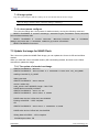
The SD card of DevKit8000 has the following software:
z x-loader--------------------------(x-load.bin.ift_for_NAND)
z u-boot------------------------------(flash-uboot.bin)
z 2.6 kernel--------------------------(uImage)
z rootfs-------------------------------(ubi.img)
In addition, the CD provides the following programs and software:
z The image files for burning
z Cross compilation tools
z Source code for each part of system
z User testing program and development demonstration
z Some tools that may be used by users when operating DevKit8000
4.1 Pre-installed software
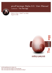
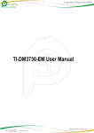
Software image has been contained in FLASH before the delivery. A completed system consists
of four parts: i.e. x-loader, u-boot, kernel and rootfs. The Figure 3.1 shows the structure of the system:
Figure 3.1 System compose map
Features and functions of each part of the system are:
1. x-loader is a first level bootstrap program. After the system start-up, the ROM inside the CPU
will copy the x-loader to internal RAM and perform work. Its main function is to initialize the CPU,
DevKit8000
User manual
Timll Technology Inc..
Version 1.0 - 5/19/2009
21 of 71
DevKit8000 user manual
copy u-boot into the memory and give the control power to u-boot;
2. u-boot is a second level bootstrap program. It is used for interacting with users and updating
images and leading the kernel;
3. The latest 2.6.x kernel is employed and can be customized based on DevKit8000;
4. Rootfs employs Open-source system. It is small in capacity and powerful.
4.2 BSP features
DevKit8000 BSP is used for customizing and generating the Linux operating system applicable to
DevKit8000 hardware platform. Users can conduct a secondary development on the basis of this
BSP. The BSP in the CD attached in DevKit8000 contains the following showed in table 3-1.
Table 3-1 BSP specifications
Item
Note
NAND / ONENAND
x-loader
MMC/SD
FAT
BIOS
NAND / ONENAND
u-boot
MMC/SD
FAT
NET
Kernel
Device Driver
GUI
Linux-2.6.x
Supports ROM/CRAM/EXT2/EXT3/FAT/NFS/
JFFS2/UBIFS and various file systems
serial
Series driver
rtc
Hardware clock driver
net
10/100M Ethernet card DM8000 driver
flash
nand flash driver (supports nand boot)
lcd
TFT LCD driver
touch
screen
Touch screen controller ads7846 driver
mmc/sd
mmc/sd controller driver
usb otg
Usb otg 2.0 driver (can be configured as
master/slave device)
dvi
Supports dvi-d signal output
s-video
Supports s-video signal output
keypad
6x6 matrix keyboard driver
led
User led lamp driver
Angstrom
release version for embedded devices’ desktop
environment
Android
google android system
DevKit8000
User manual
Timll Technology Inc..
Version 1.0 - 5/19/2009
22 of 71
DevKit8000 user manual
V Linux system quick start
5.1 system boot
Note: When you boot the board and operate the system, you may use the terminal,
Please open PC Window Hyper terminal software and set the following:
y Baud rate: 115200
y Data bit: 8
y Parity check: no
y Stop bit: 1
y Flow control: no
5.1.1 Boot from Nand Flash
The board will boot from the NAND Flash by default, the user need to link the serial cable from
the PC to the board, and power on the board, then the board will boot from NAND Flash.
Note: the method to update the image from the NAND Flash will be show in <7.2 Update the
image for NAND Flash>
5.1.2 Boot from SD card
If the board need be booting from SD card, it should press the BOOT_KEY button (the botton
position: refer the <3.18 KEY>) when power on the board, the system will boot from the SD card.
Note: the method to update the image from the SD card will be show in <7.1 Update the image
for SD card>
5.2 choose the display device
System supports a wide range of display mode; the default display mode was the 4.3”LCD, and
the user can change the display mode by change the U-Boot configure param.
5.2.1 Display with the 4.3”LCD
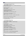
It should change the param by run the command as follow in the U-boot command mode.
1. NAND Flash boot mode
OMAP3 DevKit8000 # setenv bootargs console=ttyS2,115200n8 ubi.mtd=4 root=ubi0:rootfs
rootfstype=ubifs video=omapfb:mode:4.3inch_LCD
OMAP3 DevKit8000 # setenv bootcmd nand read.i 80300000 280000 200000\;bootm 80300000
OMAP3 DevKit8000 # saveenv
2. SD card boot mode
DevKit8000
User manual
Timll Technology Inc..
Version 1.0 - 5/19/2009
23 of 71
DevKit8000 user manual
OMAP3 DevKit8000 # setenv bootargs console=ttyS2,115200n8 root=/dev/ram
initrd=0x81600000,40M video=omapfb:mode:4.3inch_LCD
OMAP3 DevKit8000 # setenv bootcmd 'mmcinit;fatload mmc 0 80300000 uImage;fatload mmc 0
81600000 ramdisk.gz;bootm 80300000'
OMAP3 DevKit8000 # saveenv
5.2.2 Display with the 7”LCD
It should change the param by run the command as follow in the U-boot command mode.
1. NAND Flash boot mode
OMAP3 DevKit8000 # setenv bootargs console=ttyS2,115200n8 ubi.mtd=4 root=ubi0:rootfs
rootfstype=ubifs video=omapfb:mode:7inch_LCD
OMAP3 DevKit8000 # setenv bootcmd nand read.i 80300000 280000 200000\;bootm
80300000
OMAP3 DevKit8000 # saveenv
2. SD card boot mode
OMAP3 DevKit8000 # setenv bootargs console=ttyS2,115200n8 root=/dev/ram
initrd=0x81600000,40M video=omapfb:mode:7inch_LCD
setenv bootcmd 'mmcinit;fatload mmc 0 80300000 uImage;fatload mmc 0 81600000
ramdisk.gz;bootm 80300000'
OMAP3 DevKit8000 # saveenv
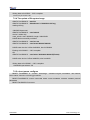
5.2.3 Display with the DVI-D
It should change the param by run the command as follow in the U-boot command mode.
1. NAND Flash boot mode
OMAP3 DevKit8000 # setenv bootargs console=ttyS2,115200n8 ubi.mtd=4 root=ubi0:rootfs
rootfstype=ubifs video=omapfb:mode:720p60
OMAP3 DevKit8000 # setenv bootcmd nand read.i 80300000 280000 200000\;bootm
80300000
OMAP3 DevKit8000 # saveenv
2. SD card boot mode
OMAP3 DevKit8000 # setenv bootargs console=ttyS2,115200n8 root=/dev/ram
initrd=0x81600000,40M video=omapfb:mode:720p60
setenv bootcmd 'mmcinit;fatload mmc 0 80300000 uImage;fatload mmc 0 81600000
ramdisk.gz;bootm 80300000'
OMAP3 DevKit8000 # saveenv
5.3 Test
5.3.1 Test on LED
LEDB, LED1, LED2 and LED3 in the board is user’ led lamp (the LED postion: refer the <3.20
LED>), of which LED1 indicates the running status of the system and LED2 indicates whether there is
data transmission with SD card.
The following show how to use the user’s led lamp LED3:
1. Please enter the following command in the terminal end to illumine the lamp led2
DevKit8000
User manual
Timll Technology Inc..
Version 1.0 - 5/19/2009
24 of 71
DevKit8000 user manual
root@DevKit8000:~#
echo -n 1 >/sys/class/leds/led3/brightness
2. Please enter the following command in the terminal end to extinguish the lamp led2
root@DevKit8000:~# echo -n 0 >/sys/class/leds/led3/brightness
The lamp LED3 will illumine and extinguish in accordance with user’s command.
5.3.2 Test on KEYPAD
The development board provides a 6x6 interface for connecting matrix keyboard. The tool evtest
can be used to test whether the matrix keyboard is in normal operation:
root@DevKit8000:~# evtest /dev/input/event0
Please press a random key in the matrix keyboard, for example, press “1”, the terminal end will show
the following:
Event: time 946684837.310027, type 1 (Key), code 2 (1), value 1
Event: time 946684837.402160, type 1 (Key), code 2 (1), value 0
Of which “type 1 (Key), code 2 (1), value 1” indicates button has been pressed, button value is “2”
(corresponds to “1” key for full-button keyboard ), status is “Pressed” (“0” represents button is
released).
Notes: Press CONTROL+C to quit the test
5.3.3 Test on touch screen
1. Run the command to test the touch screen.
root@DevKit8000:~# ts_calibrate
Then follow the LCD prompt, click the "+" icon 5 times to complete the calibration
2. Calibration is complete, enter the following commands for Touch Panel Test:
root@DevKit8000:~# ts_test
Follow the LCD prompts to choose draw point, draw line test.
Notes: Press CONTROL+C to quit the test
5.3.4 Test on RTC
The development board contains hardware clock for save and synchronize the system time. Test can
be made with the following steps:
1. Set the system time as 8:00 PM, August, 8, 2008
root@DevKit8000:~# date 080820002008
Fri Aug 8 20:00:00 UTC 2008
2. Write the system clock into RTC
root@DevKit8000:~# hwclock –w
DevKit8000
User manual
Timll Technology Inc..
Version 1.0 - 5/19/2009
25 of 71
DevKit8000 user manual
3. Read the RTC
root@DevKit8000:~# hwclock
Fri Aug 8 20:00:21 2008 0.000000 seconds
We can see that the RTC clock has been set as August, 8, 2008; the system clock will be saved in the
hardware clock.
4. Restart the system; enter the following commands to renew the system clock
root@DevKit8000:~#
hwclock –s
root@DevKit8000:~#
date
Fri Aug 8 20:01:45 UTC 2008
We can see the system time is set as hardware time.
5.3.5 Test on MMC/SD Card
Insert the MMC/SD card, the system will automatically detect and set the MMC/SD card under the
/media directory.
root@DevKit8000:~# cd /media/
root@DevKit8000:/media# ls
card
hdd
mmcblk0p1 ram
union
cf
mmc1
net
realroot
root@DevKit8000:/media# cd mmcblk0p1/
5.3.6 Test on USB OTG
1. USB OTG used as devices:
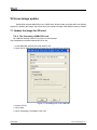
1) After booting the system, please use the USB Line (USB mini B to USB A) to connect the
development board and PC; USB mini B connects the development board, USB A connect the PC.
Notes: For the installation of driver Linux USB Ethernet/RNDIS Gadget,
please see the description in Appendix 1.
2) After successful connection, PC will show a virtual network card as displayed in Figure 4.3
Figure 4.3 virtual network card
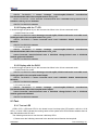
3) Set the IP address of the virtual network card, for example:
DevKit8000
User manual
Timll Technology Inc..
Version 1.0 - 5/19/2009
26 of 71
DevKit8000 user manual
Figure 4.4 IP setting
4)Set the IP address of development board and virtual network card as in the same network
segment. For example:
root@DevKit8000:~# ifconfig usb0 192.168.1.115
root@DevKit8000:~# ifconfig
lo
Link encap:Local Loopback
inet addr:127.0.0.1 Mask:255.0.0.0
UP LOOPBACK RUNNING MTU:16436 Metric:1
RX packets:26 errors:0 dropped:0 overruns:0 frame:0
TX packets:26 errors:0 dropped:0 overruns:0 carrier:0
collisions:0 txqueuelen:0
RX bytes:2316 (2.2 KiB) TX bytes:2316 (2.2 KiB)
usb0
Link encap:Ethernet HWaddr 5E:C5:F6:D4:2B:91
inet addr:192.168.1.115 Bcast:192.168.1.255 Mask:255.255.255.0
UP BROADCAST RUNNING MULTICAST MTU:1500 Metric:1
RX packets:253 errors:0 dropped:0 overruns:0 frame:0
TX packets:43 errors:0 dropped:0 overruns:0 carrier:0
collisions:0 txqueuelen:1000
RX bytes:35277 (34.4 KiB) TX bytes:10152 (9.9 KiB)
5 Test:
DevKit8000
User manual
Timll Technology Inc..
Version 1.0 - 5/19/2009
27 of 71
DevKit8000 user manual
root@DevKit8000:~# ping 192.168.1.15
PING 192.168.1.15 (192.168.1.15): 56 data bytes
64 bytes from 192.168.1.15: seq=0 ttl=128 time=0.885 ms
64 bytes from 192.168.1.15: seq=1 ttl=128 time=0.550 ms
2. USB OTG used as HOST
Please use the USB Line (USB mini B to USB A) to connect the development board and PC;
USB mini A connects the development board, USB B connect the PC.
root@DevKit8000:~# cd /media/
root@DevKit8000:/media# ls
card
hdd
mmcblk0p1 ram
sda1
cf
mmc1
net
realroot union
root@DevKit8000:/media# cd sda1
The system will automatically detect and set the USB device under the /media directory.
Notes: Some USB flash disks may be identified as sda
5.3.7 Test on Audio/Video
The board has audio input and output interface. But at present, audio output can be realized. The
system has mplayer to play the wav, mp3 and avi. Users can enter the following commands for a test:
root@DevKit8000:~# mplayer /sample_video.avi
You can hear the stereo music with a headphone and can watch the video after connecting to the
screen.
5.3.8 Test on network
The board has a 10/100M self-adapting network card DM8000; users can connect the board to the
LAN and enter the following commands for a test:
root@DevKit8000:~# ifconfig eth0 192.192.192.200
eth0: link down
root@DevKit8000:~# eth0: link up, 100Mbps, full-duplex, lpa 0x41E1
root@DevKit8000:~# ping 192.192.192.90
PING 192.192.192.90 (192.192.192.90): 56 data bytes
64 bytes from 192.192.192.90: seq=0 ttl=128 time=1.007 ms
64 bytes from 192.192.192.90: seq=1 ttl=128 time=0.306 ms
64 bytes from 192.192.192.90: seq=2 ttl=128 time=0.397 ms
64 bytes from 192.192.192.90: seq=3 ttl=128 time=0.367 ms
--- 192.192.192.90 ping statistics --4 packets transmitted, 4 packets received, 0% packet loss
round-trip min/avg/max = 0.306/0.519/1.007 ms
DevKit8000
User manual
Timll Technology Inc..
Version 1.0 - 5/19/2009
28 of 71
DevKit8000 user manual
Notes: The ip address in the network card of development board and PC
should be in the same network segment, for example: 192.192.192.x. Press
CONTROL+C to quit the test.
5.4 DevKit8000 Demo
5.4.1 The demonstration of angstrom(GPE) desktop release version
1. Famat the SD card and divided into 2 areas in accordance with appendix 2. Reload the SD card
and execute the following commands.
cp /media/cdrom/linux/demo/angstrom/MLO /media/LABEL1
cp /media/cdrom/linux/demo/angstrom/u-boot.bin /media/LABEL1
cp /media/cdrom/linux/demo/angstrom/uImage /media/LABEL1
rm –rf /media/LABEL2/*
sudo tar jxvf
linux/demo/angstrom/Angstrom-DevKit8000-demo-image-glibc-ipk-2008.1-test-2
0080111-DevKit8000.rootfs.tar.bz2 –C /media/LABEL2
sync
umount /media/LABEL1
umount /media/LABEL2
2. Insert the SD card into the development board; after booting the u-boot, kernel start-up parameters
can be set as showed below:
For LCD monitor
OMAP3 DevKit8000 # set bootargs mem=128M console=ttyS2,115200n8
root=/dev/mmcblk0p2 rw noinitrd rootdelay=1
For DVI monitor
OMAP3 DevKit8000 # set bootargs mem=128M console=ttyS2,115200n8
root=/dev/mmcblk0p2 rw noinitrd rootdelay=1 video=omapfb:mode:720p60
3. Execute the following commands to enter into the desktop system
OMAP3 DevKit8000 # mmcinit
OMAP3 DevKit8000 # fatload mmc 0 80300000 uimage
OMAP3 DevKit8000 # bootm 80300000
Notes: When entering into the desktop system for the first time, the system
will conduct considerable configuration, please wait for a few minutes. Later,
users can directly enter into the desktop after start-up.
DevKit8000
User manual
Timll Technology Inc..
Version 1.0 - 5/19/2009
29 of 71
DevKit8000 user manual
5.4.2 The demonstration of google android system
1. Famat the SD card and divided into 2 areas in accordance with appendix 2. Reload the SD card
and execute the following commands.
For the 4.3”LCD:
cp /media/cdrom/linux/demo/android/MLO /media/LABEL1
cp /media/cdrom/linux/demo/android/u-boot.bin_4.3 /media/LABEL1/u-boot.bin
cp /media/cdrom/linux/demo/android/uImage_4.3 /media/LABEL1/uImage
rm –rf /media/LABEL2/*
sudo tar jxvf linux/demo/ android/RFS.tar.bz2 –C /media/LABEL2
sync
umount /media/LABEL1
umount /media/LABEL2
For the 7”LCD:
cp /media/cdrom/linux/demo/android/MLO /media/LABEL1
cp /media/cdrom/linux/demo/android/u-boot.bin_7 /media/LABEL1/u-boot.bin
cp /media/cdrom/linux/demo/android/uImage_7 /media/LABEL1/uImage
rm –rf /media/LABEL2/*
sudo tar jxvf linux/demo/ android/RFS.tar.bz2 –C /media/LABEL2
sync
umount /media/LABEL1
umount /media/LABEL2
2. Insert the SD card into the development board; the boot the board, the board will enter the Android
system.
5.4.3 DVSDK Demo
1. Famat the SD card and divided into 2 areas in accordance with appendix 2. Reload the SD card and execute
the following commands.
For the 4.3”LCD:
cp /media/cdrom/linux/demo/dvsdk/MLO /media/LABEL1
cp /media/cdrom/linux/demo/dvsdk/u-boot.bin /media/LABEL1
cp /media/cdrom/linux/demo/dvsdk/uImage_4.3 /media/LABEL1/uImage
rm –rf /media/LABEL2/*
sudo tar jxvf linux/demo/dvsdk/DVSDK.tar.bz2 –C /media/LABEL2
sync
umount /media/LABEL1
umount /media/LABEL2
For the 7”LCD:
cp /media/cdrom/linux/demo/dvsdk/MLO /media/LABEL1
cp /media/cdrom/linux/demo/dvsdk/u-boot.bin /media/LABEL1
cp /media/cdrom/linux/demo/dvsdk/uImage_7 /media/LABEL1/uImage
rm –rf /media/LABEL2/*
sudo tar jxvf linux/demo/dvsdk/DVSDK.tar.bz2 –C /media/LABEL2
sync
umount /media/LABEL1
DevKit8000
User manual
Timll Technology Inc..
Version 1.0 - 5/19/2009
30 of 71
DevKit8000 user manual
umount /media/LABEL2
2. Insert the SD card into the development board; the boot the board, the board will enter the system
and then it will display the 2D/3D video.
DevKit8000
User manual
Timll Technology Inc..
Version 1.0 - 5/19/2009
31 of 71
DevKit8000 user manual
VI Linux System Development
This section will introduce how to establish a Linux system development platform run on DevKit8000
hardware platform with the use of DevKit8000 BSP. Details to be provided contain the formation of
cross compilation environment, the generation of system image and demonstrate how to customize
the system.
Notes: The Linux said thereof is ubuntu 7.10 which will be referred as ubuntu.
6.1 Install the cross compilation environment
User must well form an arm Linux cross compilation environment before developing the
DevKit8000. We will take ubuntu operating system as the example to introduct the formation of cross
compilation environment. The operation in Linux is similar with that in ubuntu system.
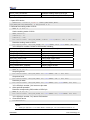
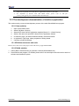
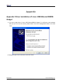
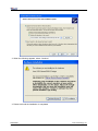
6.1.1 The installation of cross compilation tool
Insert the CD, ubuntu will put the CD under /media/cdrom directory, and the cross compilation
tool whose name is arm-2007q3-51-arm-none-linux-gnueabi.bin will be put under
/media/cdrom/linux/tools directory.
Users can execute the following commands to start up the installation of cross compilation tool:
cd /media/cdrom/linux/tools
./arm-2007q3-51-arm-none-linux-gnueabi.bin
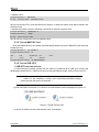
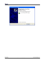
The installation can be made in accordance with the content showed. The following figure shows
the installation path
DevKit8000
User manual
Timll Technology Inc..
Version 1.0 - 5/19/2009
32 of 71
DevKit8000 user manual
Figure 5.1 the installation of cross compilation tool
Notes: The manual takes /home/embest as default installation directory. Users may change
the path.
6.1.2 The installation of other tools
Other tools included in linux/tools directory of CD may be used for source code. Users can
execute the following commands for installation:
mkdir /home/embest/tools
cp /media/cdrom/linux/tools/mkimage /home/embest/tools
cp /media/cdrom/linux/tools/signGP /home/embest/tools
cp /media/cdrom/linux/tools/mkfs.ubifs /home/embest/tools
cp /media/cdrom/linux/tools/ubinize /home/embest/tools
cp /media/cdrom/linux/tools/ ubinize.cfg /home/embest/tools
6.1.3 Adding environment variable
After installation of the above tools, those tools can be added into environment variable with the
following commands:
export
PATH=/home/embest/CodeSourcery/Sourcery_G++_Lite/bin:/home/embest/tools:$P
ATH
Notes: Users can put it into the barsrc file, and the adding of environment variable can be
finished as the system starts.
6.2 system complie
6.2.1 Preparation
The source code of each part of the system is under the linux/source of CD. Users can copy it to
the system and unzip it before developing. For example:
mkdir /home/embest/work
cd /home/embest/work
tar xvf /media/cdrom/linux/source/x-load-1.41.tar.bz2
tar xvf /media/cdrom/linux/source/u-boot-1.3.3.tar.bz2
tar xvf /media/cdrom/linux/source/linux-2.6.28-omap.tar.bz2
sudo tar xvf /media/cdrom/linux/source/rootfs.tar.bz2
When the above steps are finished, the current directory will generate linux-2.6.22-omap,
u-boot-1.3.3 and x-load-1.41 these three directories.
6.2.2 x-loader image generated
DevKit8000 supports MMC/SD boot or NAND boot. The burned x-loader image files are different
with the different boot modes, and the corresponding methods for mapping will differ too.
DevKit8000
User manual
Timll Technology Inc..
Version 1.0 - 5/19/2009
33 of 71
DevKit8000 user manual
We will introduce the generation of x-loader image file under different boot modes.
1. To generate x-loader image file MLO used for SD card start-up
When the above steps are finished, the current directory will generate the file MLO we need.
cd x-load-1.41
make distclean
make omap3devkit8000_config
make
signGP x-load.bin
mv x-load.bin.ift MLO
2. To generate the x-load.bin.ift_for_NAND start-up
1) To alter the file x-loader-1.4.1/include/configs/omap3DevKit8000.h and annotate the following:
//#define CFG_CMD_MMC
1
2) Cross compilation
cd x-load-1.41
make distclean
make omap3devkit8000_config
make
signGP x-load.bin
mv x-load.bin.ift x-load.bin.ift_for_NAND
When the above steps are finished, the current directory will generate the file
x-load.bin.ift_for_NAND we need.
6.2.3 u-boot image generated
cd u-boot-1.3.3
make distclean
make omap3devkit8000_config
make
When the above steps are finished, the current directory will generate the file u-boot.bin we
need.
6.2.4 kernel image generated
cd linux-2.6.28-omap
make distclean
make omap3_devkit8000_defconfig
make uImage
When the above steps are finished, the arch/arm/boot directory will generate the file uImage we
need.
6.2.5 ubifs image generated
cd /home/embest/work
DevKit8000
User manual
Timll Technology Inc..
Version 1.0 - 5/19/2009
34 of 71
DevKit8000 user manual
sudo mkfs.ubifs -r rootfs -m 2048 -e 129024 -c 812 -o ubifs.img
sudo ubinize -o ubi.img -m 2048 -p 128KiB -s 512 /home/embest/tools/ubinize.cfg
When the above steps are finished, the current directory will generate the file ubi.img we need.
6.3 System Customization
Actually, Linux kernel has many options for configuring the kernel. According to the default
configuration, users can add or delete some configuration to suit different need. The following
example illustrates the general process of system customization.
6.3.1 Alteration of kernel configuration
Kernel source code provides the default configuration file:
arch/arm/configs/omap3_DevKit8000_defconfig
Users can customize the system on the basis of this file
cd linux-2.6.28-omap
cp arch/arm/configs/omap3_devkit8000_defconfig .config
make menuconfig
The example that we use usb gadget to simulate usb mass storage device will be taken to
introduce the system customization:
1. Select Device drivers
2. Select USB support
DevKit8000
User manual
Timll Technology Inc..
Version 1.0 - 5/19/2009
35 of 71
DevKit8000 user manual
3. Select USB Gadget Support
DevKit8000
User manual
Timll Technology Inc..
Version 1.0 - 5/19/2009
36 of 71
DevKit8000 user manual
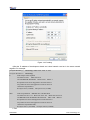
4. The configuration of USB Gadget Support can be changed as showed in the following
6.3.2 Compilation
Save the configuration and execute the following command to recompile the kernel:
make
make uImage
After the above steps are finished, arch/arm/boot directory will generate a new kernel image
zImage; drivers/usb/gadget directory will generate a new module file g_file_storage.ko.
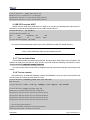
6.3.3 Test
Update kernel image file zlmage in SD card, copy file g_file_storage.ko to the SD card and
reboot the system. Execute the following commands to stimulate the sd card into usb mass storage
device for PC’s visit:
root@DevKit8000:~# cd /media/mmcblk0p1/
root@DevKit8000:/media/mmcblk0p1# insmod g_file_storage.ko file=/dev/mmcblk0p1
stall=0 removable=1
g_file_storage gadget: File-backed Storage Gadget, version: 7 August 2007
g_file_storage gadget: Number of LUNs=1
g_file_storage gadget-lun0: ro=0, file: /dev/mmcblk0p1
musb_hdrc musb_hdrc: MUSB HDRC host driver
musb_hdrc musb_hdrc: new USB bus registered, assigned bus number 2
usb usb2: configuration #1 chosen from 1 choice
hub 2-0:1.0: USB hub found
hub 2-0:1.0: 1 port detected
DevKit8000
User manual
Timll Technology Inc..
Version 1.0 - 5/19/2009
37 of 71
DevKit8000 user manual
Use the USB line (USB mini B to USB A) to connect the development board and PC, PC will give
a hint that usb mass storage device is found; a new mobile hard disk is found and users can perform
operation for it.
Notes: Please make sure that the kernel image has been updated, otherwise, module
g_file_storage.ko will fail to load and the similar tips will show:
insmod: cannot insert '/media/mmcblk0p1/g_file_storage.ko': Device or resource busy
DevKit8000
User manual
Timll Technology Inc..
Version 1.0 - 5/19/2009
38 of 71
DevKit8000 user manual
VII Linux image update
DevKit8000 supports MMC/SD boot or NAND boot; different start-up modes will have different
method for updating the image. We will introduce the update of image under different start-up modes.
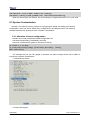
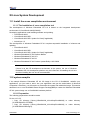
7.1 Update the image for SD card
7.1.1 The formatting of MMC/SD card
HP USB Disk Storage Format Tool 2.0.6 is recommended:
http://selfdestruct.net/misc/usbboot/SP27213.exe
1. Insert MMC/SD card into the card reader in PC
2. Open the HP USB Disk Storage Format Tool, the following tips will show:
Figure 7.1 Formatting tool of HP USB Disk
3. Select “FAT32”
4. Click “Start”
5. When formatting is completed, click “OK”
DevKit8000
User manual
Timll Technology Inc..
Version 1.0 - 5/19/2009
39 of 71
DevKit8000 user manual
7.1.2 Image update
Copy the system image to SD card. Then you can use the SD card for the new image.
Note: the image contains: MLO, u-boot.bin, uImage, ramdisk.gz
7.1.3 u-boot param configure
The user can change the U-boot param for defaut mode by running the following command.
OMAP3 DevKit8000 # setenv bootargs console=ttyS2,115200n8 root=/dev/ram
initrd=0x81600000,40M
OMAP3 DevKit8000 # setenv bootcmd 'mmcinit;fatload
uImage;fatload mmc 0 81600000 ramdisk.gz;bootm 80300000'
mmc
0
80300000
OMAP3 DevKit8000 # saveenv
7.2 Update the image for NAND Flash
The U-boot can update the NAND Flash image; you can update the U-boot via SD card as follow
method.
When you enter the U-boot commad mode by SD card booting method, and then run the follow
command to update the image.
7.2.1 The update of x-loader boot image
OMAP3 DevKit8000 # mmcinit
OMAP3 DevKit8000 # fatload mmc 0:1 80000000 x-load.bin.ift_for_NAND
reading x-load.bin.ift_for_NAND
9664 bytes read
OMAP3 DevKit8000 # nand unlock
device 0 whole chip
nand_unlock: start: 00000000, length: 134217728!
NAND flash successfully unlocked
OMAP3 DevKit8000 # nand ecc hw
OMAP3 DevKit8000 # nand erase 0 80000
NAND erase: device 0 offset 0x0, size 0x80000
Erasing at 0x60000 -- 100% complete.
OK
OMAP3 DevKit8000 # nand write.i 80000000 0 80000
NAND write: device 0 offset 0x0, size 0x80000
Writing data at 0x7f800 -- 100% complete.
524288 bytes written: OK
DevKit8000
User manual
Timll Technology Inc..
Version 1.0 - 5/19/2009
40 of 71
DevKit8000 user manual
7.2.2 The update of u-boot boot image
OMAP3 DevKit8000 # mmcinit
OMAP3 DevKit8000 # fatload mmc 0:1 80000000 flash-uboot.bin
reading flash-uboot.bin
1085536 bytes read
OMAP3 DevKit8000 # nand unlock
device 0 whole chip
nand_unlock: start: 00000000, length: 134217728!
NAND flash successfully unlocked
OMAP3 DevKit8000 # nand ecc sw
OMAP3 DevKit8000 # nand erase 80000 160000
NAND erase: device 0 offset 0x80000, size 0x160000
Erasing at 0x1c0000 -- 100% complete.
OK
OMAP3 DevKit8000 # nand write.i 80000000 80000 160000
NAND write: device 0 offset 0x80000, size 0x160000
Writing data at 0x1df800 -- 100% complete.
1441792 bytes written: OK
7.2.3 The update of kernel image
OMAP3 DevKit8000 # mmcinit
OMAP3 DevKit8000 # fatload mmc 0:1 80000000 uImage
reading uImage
1991900 bytes read
OMAP3 DevKit8000 # nand unlock
device 0 whole chip
nand_unlock: start: 00000000, length: 268435456!
NAND flash successfully unlocked
OMAP3 DevKit8000 #
OMAP3 DevKit8000 #
nand ecc sw
nand erase 280000 200000
NAND erase: device 0 offset 0x280000, size 0x200000
Erasing at 0x460000 -- 100% complete.
OK
OMAP3 DevKit8000 #
nand write.i 80000000 280000 200000
NAND write: device 0 offset 0x280000, size 0x200000
DevKit8000
User manual
Timll Technology Inc..
Version 1.0 - 5/19/2009
41 of 71
DevKit8000 user manual
Writing data at 0x47f800 -- 100% complete.
2097152 bytes written: OK
7.2.4 The update of filesystem image
OMAP3 DevKit8000 # mmcinit
OMAP3 DevKit8000 # fatload mmc 0:1 80000000 ubi.img
reading ubi.img
12845056 bytes read
OMAP3 DevKit8000 # nand unlock
device 0 whole chip
nand_unlock: start: 00000000, length: 268435456!
NAND flash successfully unlocked
OMAP3 DevKit8000 #
OMAP3 DevKit8000 #
nand ecc sw
nand erase 680000 7980000
NAND erase: device 0 offset 0x680000, size 0x7980000
Erasing at 0x7fe0000 -- 100% complete.
OK
OMAP3 DevKit8000 #
nand write.i 80000000 680000 $(filesize)
NAND write: device 0 offset 0x680000, size 0xc40000
Writing data at 0x12bf800 -- 100% complete.
12845056 bytes written: OK
7.2.5 u-boot param configure
OMAP3 DevKit8000 # setenv bootargs
root=ubi0:rootfs rootfstype=ubifs
console=ttyS2,115200n8
ubi.mtd=4
OMAP3 DevKit8000 # setenv bootcmd nand read 80300000 280000 200000\;bootm
80300000
OMAP3 DevKit8000 # saveenv
DevKit8000
User manual
Timll Technology Inc..
Version 1.0 - 5/19/2009
42 of 71
DevKit8000 user manual
VIII The development of application
This section will introduce how to conduct the development of application on the DevKit8000
hardware platform, including the formation of DevKit8000 software environment. Examples will be
taken to show the general process of the development of DevKit8000 application.
8.1 LED application development
8.1.1 Coding
led_acc.c source code, The three led lamps in the development board will flash in the form of
accumulator
#include <stdio.h>
#include <unistd.h>
#include <sys/types.h>
#include <sys/ipc.h>
#include <sys/ioctl.h>
#include <fcntl.h>
#define LED0 "/sys/class/leds/led0/brightness"
#define LED1 "/sys/class/leds/led1/brightness"
#define LED2 "/sys/class/leds/led2/brightness"
int main(int argc, char *argv[])
{
int f_led0, f_led1, f_led2;
unsigned char i = 0;
unsigned char dat0, dat1, dat2;
if((f_led0 = open(LED0, O_RDWR)) < 0){
printf("error in open %s",LED0);
return -1;
}
if((f_led1 = open(LED1, O_RDWR)) < 0){
printf("error in open %s",LED1);
return -1;
}
if((f_led2 = open(LED2, O_RDWR)) < 0){
printf("error in open %s",LED2);
return -1;
}
for(;;){
i++;
dat0 = i&0x1 ? '1':'0';
dat1 = (i&0x2)>>1 ? '1':'0';
DevKit8000
User manual
Timll Technology Inc..
Version 1.0 - 5/19/2009
43 of 71
DevKit8000 user manual
dat2 = (i&0x4)>>2 ? '1':'0';
write(f_led0, &dat0, sizeof(dat0));
write(f_led1, &dat1, sizeof(dat1));
write(f_led2, &dat2, sizeof(dat2));
usleep(300000);
}
}
8.1.2 Cross compilation
arm-none-linux-gnueabi-gcc led_acc.c –o led_acc
8.1.3 Download and run
Resources can be put into the system in the way of SD card or U flash card or download. Then enter
the directory that file led_acc exists, and input the following commands and enter, then the led_acc
will run in the background.
./led_acc &
DevKit8000
User manual
Timll Technology Inc..
Version 1.0 - 5/19/2009
44 of 71
DevKit8000 user manual
Chapter Four: WinCE System
IX WinCE system Overview
DevKit8000 software system includes: pre-compiled images and applications and their corresponding
static library, dynamic link library, header file and source code; cross compilation tools, auxiliary tools
for development. Images, applications, Cross compilation tools used for generating image and
application can be downloaded from Microsoft. Image, application, source code and auxiliary tools of
DevKit8000 can be found in the release CD or SD card of DevKit8000 .
The SD card of DevKit8000 has the following software:
y X-Loader image(MLO)
y Ethernet Bootloader(EBOOT)image(EBOOTSD.nb0)
y Windows Embedded CE 6.0 sample OS image(NK.bin)
y Test programmer(DevKit8000.exe)
The CD of DevKit8000 includes:
y Windows Embedded CE 6.0 DevKit8000 Board Support Package(BSP)source code for TI
OMAP35X
y Windows Embedded CE 6.0 project for DevKit8000 BSP
y DevKit8000 application development example(source code)
y Auxiliary development tools
This section mainly introduces and DevKit8000 software system and covers description of
pre-compiled images and BSP and test kit, some functions and features of various images and
applications in the CD.
9.1 Pre-compiled image
The pre-compiled images include boot image X-Loader and EBOOT and sample OS image. X-Loader
is a first level guidance code. After the start-up of system, the ROM inside the CPU will copy the
x-loader to internal RAM and perform work. Its main function is to initialize the CPU, and copy
EBOOT to DDR memory and execute EBOOT. EBOOT is a second level guidance code, by default, it
will copy system image to DDR memory and hand the control right to the operating system. EBOOT
also can provide related functions to manage the basic hardware and set the shared data in operating
system.
Taking Mobile Handheld as an example, the pre-compiled images support the following:
Image
Feature
X-Loader
To boot EBOOT
EBOOT
To boot the operating system from the
network (network card or RNDIS)
To boot the operating system with SD card
To boot the operating system from the
DevKit8000
User manual
Timll Technology Inc..
Version 1.0 - 5/19/2009
45 of 71
DevKit8000 user manual
NAND Flash
Demonstrated operating system
Windows Explorer
Console Window
CAB File Installer/Uninstaller
Internet Explorer 6.0
ActiveSync
Power Management (Full)
.NET Compact Framework 3.5
Hive-based Registry
RAM and ROM File System
Device Drivers
9.2 Board Support Package(BSP)
DevKit8000 BSP is used to customize the boot image and Windows Embedded CE 6.0 OS image run
on DevKit8000 hardware platform. It supports the following:
Module
Feature
X-Loader module
NAND
ONENAND
SD
EBOOT module
NAND
ONENAND
SD
OAL module
ILT
REBOOT
Watchdog
RTC
KITL module
RNDIS KITL
Driver module
NLED driver
GPIO/I2C/SPI/MCBSP driver
Series port driver
6X6 keyboard driver
Audio driver
NAND(K9F1G08)driver
Display driver(LCD/DVI.
TOUCH driver
S
end/TV)/
SD/MMC/SDIO driver
DM9000 network card driver
USB OTG driver
USB EHCI driver
VRFB driver
DSPLINKK/CMEMK driver
GPIO keyboard driver
DevKit8000
User manual
Timll Technology Inc..
Version 1.0 - 5/19/2009
46 of 71
DevKit8000 user manual
PWM(TPS65930)driver
ADC(TPS65930)driver
ONENAND driver
SMSC911X network card driver
Power management module
Backlight driver
Battery driver
Sleep / wake-up button driver
Expansion of power management
Application module
Flash Plug-in and Flash player
MP3/MPEG4/H264 DSP Hardware decoder
BSPINFO(control panel)
CETK
Note:
DevKit8000 hardware platform may not support some modules
Some library and source code provided by BSP may subject to third-party copyright
DevKit8000
User manual
Timll Technology Inc..
Version 1.0 - 5/19/2009
47 of 71
DevKit8000 user manual
X WinCE system quick start
10.1 system boot
Note: When you boot the board and operate the system, you may use the terminal, Please open
PC Window Hyper terminal software and set the following:
y Baud rate: 115200
y Data bit: 8
y Parity check: no
y Stop bit: 1
y Flow control: no
10.1.1 Boot from Nand Flash
The board will boot from the NAND Flash by default, the user need to link the serial cable from the PC to the
board, and power on the board, then the board will boot from NAND Flash.
Note: the method to update the image from the NAND Flash will be show in <12.2 Update the
image for NAND Flash>
10.1.2 Boot from SD card
If the board need be booting from SD card, it should press the BOOT_KEY button (the botton position:
refer the <3.18 KEY>) when power on the board, the system will boot from the SD card.
Note: the method to update the image from the SD card will be show in <12.1 Update the
image for SD card>
10.2 Test
10.2.1 introduce
DevKit8000 board test kit is the application of Windows Embedded CE 6.0 and is used to test
DevKit8000 software and hardware platform. It supports the following features:
y Automatic test on SD card
y Automatic test on NAND Flash disk
y Automatic test on network
y Manual test on keyboard
y Automatic test on RTC
y Semi-automatic test on NLED
y Semi-automatic test on audio output and input
y Semi-automatic test on LCD display
DevKit8000
User manual
Timll Technology Inc..
Version 1.0 - 5/19/2009
48 of 71
DevKit8000 user manual
10.2.2 Test on software and hardware system
Note: you should link the serial cable from PC to the board, and link the LCD, key, audio out
and audio in device to the board, if you don’t link the device, it should impact the test results.
Open PC Window Hyper terminal software and set the following:
y Baud rate: 115200
y Data bit: 8
y Parity check: no
y Stop bit: 1
y Flow control: no
Please shut down the PC firewall or enable the LAN data communication and set the following:
y IP address: 192.168.1.2
y Subnet mask: 255.255.255.0
1. Windows Embedded CE 6.0. Insert the SD card and boot the system, hyper terminal
will show start-up information. After a while, you can enter the system and experience
Windows Embedded CE 6.0
2. If the touch screen is not accurate, please calibrate it (Stylus Properties window,
Calibration property page [My Device\Control Panel\Stylus])
3. Run the test program ADevKit8000.exe[\Storage Card].
4. Click “Start” and the test will begin.
5. Keypad window will show, test the keyboard, press ESC button or click “Quit” to quit the
test.
6. LED will be blinking, and waiting for users to judge.
7. Boot sound can be heard.
8. The screen will show RGB three primary colors in turn; touch the screen to quit the test.
9. After the test is completed, the results will show in test edit box: “SUCCESS” means the
test is passed; “FAILED” means the test is not passed.
Notes:
If the file system in the SD card is damaged, Please recover the image referring to “6.3
The update of the image.
DevKit8000
User manual
Timll Technology Inc..
Version 1.0 - 5/19/2009
49 of 71
DevKit8000 user manual
XI Linux System Development
11.1 Install the cross compilation environment
11.1.1 The installation of cross compilation tool
The development of Windows Embedded CE 6.0 is based on the integrated development
environment of Visual Studio 2005(VS2005).
Developing applications need installing software and updating:
y Visual Studio 2005
y Visual Studio 2005 SP1
y Visual Studio 2005 SP1 Update for Vista (if applicable)
y ActiveSync 4.5
The development of Windows Embedded CE 6.0 requires sequential installation of software and
updating:
y Visual Studio 2005
y Visual Studio 2005 SP1
y Visual Studio 2005 SP1 Update for Vista (if applicable)
y Windows Embedded CE 6.0 Platform Builder
y Windows Embedded CE 6.0 SP1
y Windows Embedded CE 6.0 R2
y Windows Embedded CE 6.0 Product Update Rollup 12/31/2008
Notes:
If there is an old CE development environment in the system, the use of Windows
Embedded CE 6.0 development platform may be influenced. Uninstalling the old one
and then installing the new one is recommended.
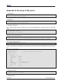
11.2 system complie
If the sample Windows Embedded CE 6.0 OS image in the CD of DevKit8000 satisfies your
applications, you just need to add it into your application and get the authorization of Microsoft
Corporation. Otherwise, you will need to re-customize the system and rebuild the image. This section
describes how to use DevKit8000 Board Support Package(BSP)to create the Windows Embedded
CE 6.0 system image run on DevKit8000 hardware platform.
11.2.1 Preparation
The following preparations should be made:
For the 4.3”LCD:
y Copy CD directory [\wince_6\DevKit8000_4.3inch\bsp\DevKit8000] to under directory
[C:\WINCE600\PLATFORM].
y Copy CD directory [\wince_6\DevKit8000_4.3inch\bsp\DevKit8000] to under directory
[C:\WINCE600\OSDesigns].
DevKit8000
User manual
Timll Technology Inc..
Version 1.0 - 5/19/2009
50 of 71
DevKit8000 user manual
For the 7”LCD:
y Copy CD directory [\wince_6\DevKit8000_7inch\bsp\DevKit8000]
[C:\WINCE600\PLATFORM].
y Copy CD directory [\wince_6\DevKit8000_7inch\bsp\DevKit8000]
[C:\WINCE600\OSDesigns].
to
under
directory
to
under
directory
Notes:
If user needs to use DevKit8000 BS to develop Windows Embedded CE 6. operating system, the
construction of Windows Embedded CE 6.0 development platform is required.
This manual takes the default installation path for Windows Embedded CE 6.0 software, i.e. its
default path is [C:\WINCE600].
11.2.2 system complie
1.
Open the file DevKit8000.sln[C:\WINCE600\OSDesigns\DevKit8000] or take the following steps
to create a new project:
a) Open Visual Studio 2005.
b) Select the menu: File[New->Project].
c) Select template type of Platform Builder for CE 6.0
d) Select a file name and open Windows Embedded CE 6.0 OS Design Wizard
e) Set the Embest DevKit8000 BSP into the BSP list.
f) Continue to finish the Wizard.
2. Select submenu [Build-> Global Build Settings]
y Copy Files to Release Directory After Build
y Make Run-Time Image After build
3. If KITL is needed, set Enable Kernel Debugger and Enable KITL into Build Options page
[Project-> Properties].
4. Select [Build-> Build Solution] to build BSP. These operations cover the whole compilation
including sysgen operating system’s components. After a entire compilation process is
completed, the build commands under Solution Explorer window can be used to save the build
time.
Images including NK.bin, EBOOTSD.nb0 and MLO and so on will be generate;
Copy
the
files
MLO,
EBOOTSD.nb0
and
NK.bin
under
[C:\WINCE600\OSDesigns\DevKit8000\DevKit8000\RelDir\DevKit8000_ARMV4I_Release] to the SD
card. Insert the SD card into the device and boot the device for a test.
11.2.3 System Customization
Windows Embedded CE 6.0 consists of a number of independent modules. Each module provides
specific functions, of which some modules can be divided into several components. Each component
has specific feature, making OEM/ODM customize a stable and efficient version according to specific
application.
Taking Mobile Handheld as a template, sample DevKit8000 OS image adds features of components
including:
DevKit8000
User manual
Timll Technology Inc..
Version 1.0 - 5/19/2009
51 of 71
DevKit8000 user manual
Component
Path
CAB File Installer/Uninstaller
Core OS->CEBASE->Application – End User
.NET Compact Framework 3.5
Core
OS->CEBASE->Applications
and
Services
Development->.NET
Compact
Framework 3.5
OS Dependencies
Framework 3.5
for
.NET
Compact
Core
OS->CEBASE->Applications
and
Services
Development->.NET
Compact
Framework 3.5-> OS Dependencies for .NET
Compact Framework 3.5
Point-to-Point Protocol over Ethernet (PPPoE)
Core OS->CEBASE->Communication Services
and Networking->Networking – Wide Area
Network (WAN)
USB Function Driver
Core OS->CEBASE->Core OS Services->USB
Host Support
USB Host Support
Core OS->CEBASE->Core OS Services->USB
Host Support
USB Human Input Device (HID) Class Driver
Core OS->CEBASE->Core OS Services->USB
Host Support
USB HID Keyboard and Mouse
Core OS->CEBASE->Core OS Services->USB
Host Support-> USB Human Input Device
(HID) Class Driver
USB Storage Class Driver
Core OS->CEBASE->Core OS Services->USB
Host Support
RAM and ROM File System
Core OS->CEBASE->File Systems and Data
Store->File System – Internal (Choose 1)
Hive-based Registry
Core OS->CEBASE->File Systems and Data
Store->Registry Storage – Internal (Choose 1)
exFAT File System
Core OS->CEBASE->File Systems and Data
Store->Storage Manager
FAT File System
Core OS->CEBASE->File Systems and Data
Store->Storage Manager
Storage Manager Control Panel Applet
Core OS->CEBASE->File Systems and Data
Store->Storage Manager
Transaction-Safe FAT File System (TFAT)
Core OS->CEBASE->File Systems and Data
Store->Storage Manager
Video/Image Compression Manager
Core
OS->CEBASE->Graphics
and
Multimedia
Technologies->Media->Video
Codecs and Renderers
Console Window
Core
OS->CEBASE->Shell
and
Interface->Shell->Command Shell
SD Memory
Device Drivers->SDIO->SDIO Memory
serial
Device
Drivers->USB
Function Clients
DevKit8000
User manual
User
Function->USB
Timll Technology Inc..
Version 1.0 - 5/19/2009
52 of 71
DevKit8000 user manual
Windows Embedded CE Test Kit
Device Drivers
Components can be added or deleted in window Catalog Items View of Visual Studio 2005(VS2005)
integrated development environment.
DevKit8000
User manual
Timll Technology Inc..
Version 1.0 - 5/19/2009
53 of 71
DevKit8000 user manual
XII WinCE image update
12.1 Update the image for SD card
(1)Run the software of HP Disk Storage Format Tool and format the SD card for FAT or FAT32 filesystem.
(2) Copy the image file(MLO, EBOOTSD.nb0, NK.bin, ADevKit8000.exe) in CD:\wince_6\image\
lcd480X272 to SD card.
(3) Then you can boot the system with the SD for the new image.
Note:
1) You can download the software HP USB Disk Storage Format Tool 2.0.6 from the follow
website: http://selfdestruct.net/misc/usbboot/SP27213.exe
2) The folder of dvi1280X720 was corresponding DVI output image file, and the lcd480X272
was LCD output image.
12.2 Update the image for NAND Flash
(1)Run the software of HP Disk Storage Format Tool and format the SD card for FAT or FAT32
filesystem.
(2) Copy the image file(MLO, EBOOTNAND.nb0, NK.bin, ADevKit8000.exe) from
CD:\wince_6\image\ lcd480X272 to SD card, then change the name from EBOOTNAND.nb0 to
EBOOTSD.nb0 in the SD card.
(3) Insert the SD card to the board, press the BOOT button and then power on the board again;
HyperTerminal will start printing the output information, at the same time press [SPACE] to enter the
EBOOT menu.
(4) Press [5] to enter the Flash manage menu.
(5) Press [a], [b], [c] separately to write the image(XLDR, EBOOT, NK) to flash.
(6) Press [0] to return to the main menu, and press [2], [4], [7], [y] to change the boot device.
(7) Power on the system again, and then the board will boot from the NAND flash.
DevKit8000
User manual
Timll Technology Inc..
Version 1.0 - 5/19/2009
54 of 71
DevKit8000 user manual
XIII The development of application
This section introduces how to develop the application run on DevKit8000 hardware platform on the
basis of Windows Embedded CE 6.0 operating system. The following preparations should be made:
y Run
the
installation
package
DevKit8000
Software
Development
Kit(SDK)(DevKit8000_SDK.msi)under CD directory [\wince_6\sdk], and finish the SDK installation in
accordance with hints.
Notes:
1. If user needs to use DevKit8000 BS to develop Windows Embedded CE 6. operating system, the
construction of Windows Embedded CE 6.0 development platform is required.
2. The installation of Windows Mobile 6 Professional SDK other than DevKit8000 SDK is advised.
You
can
obtain
this
software
through
[http://www.microsoft.com/downloads/details.aspx?familyid=06111A3A-A651-4745-88EF-3D480
91A390B&displaylang=en].
3. The development example of this manual is based on the development of Windows Mobile 6
Professional SDK.
13.1 The interface and demonstration of application
The Application Programming Interface(API)used by DevKit8000 application development employs
the standard application interface of Windows Embedded CE 6.0. DevKit8000 just has an additional
GPIO interface based on standard API.
Note:
1. For interface definition of Windows Embedded CE 6.0 standard application, please refer
to related help documents of MSDN Windows Embedded CE 6.0 API.
2. The example of the use of standard API is provided in the section of ” 7.2 The development
demonstration of interface application”.
3. Some interfaces are just used for drivers. They can’t be used by the application
programmer..
13.1.1The definition and demonstration of GPIO interface
GPIO device name L"GIO1:", to expand DeviceIoControl interface definition, corresponding IOCTL
code includes:
IOCTL Code
Description
IOCTL_GPIO_SETBIT
Set GPIO pin as 1
IOCTL_GPIO_CLRBIT
Set GPIO pin as 0
IOCTL_GPIO_GETBIT
Read GPIO pin
IOCTL_GPIO_SETMODE
Set the working mode of GPIO pin
DevKit8000
User manual
Timll Technology Inc..
Version 1.0 - 5/19/2009
55 of 71
DevKit8000 user manual
IOCTL_GPIO_GETMODE
Read the working mode of GPIO pin
IOCTL_GPIO_GETIRQ
Read the corresponding IRQ of GPIO pin
Operation example is showed below:
1. Open GPIO device
HANDLE hFile = CreateFile(_T("GIO1:"), (GENERIC_READ|GENERIC_WRITE),
(FILE_SHARE_READ|FILE_SHARE_WRITE), 0, OPEN_EXISTING, 0, 0);
2. Set/read the working mode of GPIO
DWORD id = 0, mode = 0;
Set the working mode of GPIO:
DWORD pInBuffer[2];
pInBuffer[0] = id;
pInBuffer[1] = mode;
DeviceIoControl(hFile, IOCTL_GPIO_SETMODE, pInBuffer, sizeof(pInBuffer), NULL, 0, NULL, NULL);
Read the working mode of GPIO:
DeviceIoControl(hFile, IOCTL_GPIO_GETMODE, &id, sizeof(DWORD), &mode, sizeof(DWORD), NULL, NULL);
"id" is GPIO Pin number, "mode" is GPIO mode, including:
Mode definition
Description
GPIO_DIR_OUTPUT
Output mode
GPIO_DIR_INPUT
Input mode
GPIO_INT_LOW_HIGH
Rising edge trigger mode
GPIO_INT_HIGH_LOW
Falling edge trigger mode
GPIO_INT_LOW
low level trigger mode
GPIO_INT_HIGH
high level trigger mode
GPIO_DEBOUNCE_ENABLE
Jumping trigger enable
1.
The operation of GPIO Pin
DWORD id = 0, pin = 0;
Output high level:
DeviceIoControl(hFile, IOCTL_GPIO_SETBIT, &id, sizeof(DWORD), NULL, 0, NULL, NULL);
Output low level:
DeviceIoControl(hFile, IOCTL_GPIO_CLRBIT, &id, sizeof(DWORD), NULL, 0, NULL, NULL);
Read the pin state
DeviceIoControl(hFile, IOCTL_GPIO_GETBIT, &id, sizeof(DWORD), &pin, sizeof(DWORD), NULL, NULL);
2.
"id" is GPIO pin number, "pin" returns to pin state
Other optional operation
Read the corresponding IRQ number of GPIO pin
DWORD id = 0, irq = 0;
DeviceIoControl(hFile, IOCTL_GPIO_GETIRQ, &id, sizeof(DWORD), &irq, sizeof(DWORD), NULL, NULL);
3.
"id" is GPIO pin number, "irq" returns IRQ number
Close GPIO device
CloseHandle(hFile);
Notes:
1. GPIO pin definition: 0~191 MPU Bank1~6 GPIO pin, 192~209 TPS65930 GPIO 0~17.
DevKit8000
User manual
Timll Technology Inc..
Version 1.0 - 5/19/2009
56 of 71
DevKit8000 user manual
2.
3.
GPIO interrupt mode is used for drivers, application cannot set this mode.
For definition of IOCTL code and GPIO mode, please refer to CD file
[\wince_6\inc\gpio.h] User should include the header file.
13.2 The development demonstration of interface application
This section mainly covers the development process of the said ADevKit8000 test program.
13.2.1 New solution
1.
2.
3.
4.
5.
6.
7.
Open Visual Studio 2005.
Select File [New->Project].
Select MFC Smart Device Application template [Visual C++->Smart Device].
Select a file name and open MFC Smart Device Application Wizard.
In Platforms page, just select Windows Mobile 6 Professional SDK.
In Application Type page, select properties of Dialog based.
Continue to finish the Wizard.
13.2.2 Edit the resources and code
Please refer to the source code project in the CD:\wince_6\app\ADevKit8000.
13.2.3 Build solution
1.
2.
Select [Build-> Build Solution] to generate a solution(ADevKit8000.exe).
Download the test program. For details, please refer to the description about the test in section of
software and hardware system.
DevKit8000
User manual
Timll Technology Inc..
Version 1.0 - 5/19/2009
57 of 71
DevKit8000 user manual
Appendix
Appendix I Driver installation of Linux USB Ethernet/RNDIS
Gadget
1. If you don’t install driver of Linux USB Ethernet/RNDIS Gadget, PC will find the new hardware
and give you a hint on the screen, please select “From list or designated location”, then click
“Next”
2. Designate a path for the usb driver, then click “Next”
DevKit8000
User manual
Timll Technology Inc..
Version 1.0 - 5/19/2009
58 of 71
DevKit8000 user manual
3. When the following appears, select “Continue”
4. Please wait until the installation is completed
DevKit8000
User manual
Timll Technology Inc..
Version 1.0 - 5/19/2009
59 of 71
DevKit8000 user manual
DevKit8000
User manual
Timll Technology Inc..
Version 1.0 - 5/19/2009
60 of 71
DevKit8000 user manual
Appendix II Linux Boot Disk Format
How to create a dual-partition card for DevKit8000 to boot Linux from first partition and have root file
system at second partition
Introduction
This guide is meant for those looking to create a dual-partition card, booting from a FAT partition that
can be read by the OMAP3 ROM bootloader and Linux/Windows, then utilizing an ext3 partition for
the Linux root file system.
Details
Text marked with [] shows user input.
1. Determine which device the SD Card Reader is on your system
Plug the SD Card into the SD Card Reader and then plug the SD Card Reader into your system. After
doing that, do the following to determine which device it is on your system.
$ [dmesg | tail]
...
[ 6854.215650] sd 7:0:0:0: [sdc] Mode Sense: 0b 00 00 08
[ 6854.215653] sd 7:0:0:0: [sdc] Assuming drive cache: write through
[ 6854.215659] sdc: sdc1
[ 6854.218079] sd 7:0:0:0: [sdc] Attached SCSI removable disk
[ 6854.218135] sd 7:0:0:0: Attached scsi generic sg2 type 0
...
In this case, it shows up as /dev/sdc (note sdc inside the square brackets above).
2. Check to see if the automounter has mounted the SD Card
Note there may be more than one partition (only one shown in the example below).
$ [df -h]
Filesystem
Size Used Avail Use% Mounted on
...
/dev/sdc1
400M 94M 307M 24% /media/disk
...
Note the "Mounted on" field in the above and use that name in the umount commands below.
3. If so, unmount it
$ [umount /media/disk]
4. Start fdisk
Be sure to choose the whole device (/dev/sdc), not a single partition (/dev/sdc1).
$ [sudo fdisk /dev/sdc]
5. Print the partition record
DevKit8000
User manual
Timll Technology Inc..
Version 1.0 - 5/19/2009
61 of 71
DevKit8000 user manual
So you know your starting point. Make sure to write down the number of bytes on the card (in this
example, 2021654528).
Command (m for help): [p]
Disk /dev/sdc: 2021 MB, 2021654528 bytes
255 heads, 63 sectors/track, 245 cylinders
Units = cylinders of 16065 * 512 = 8225280 bytes
Device Boot
Start
End
Blocks Id System
/dev/sdc1 *
1
246
1974240+ c W95 FAT32 (LBA)
Partition 1 has different physical/logical endings:
phys=(244, 254, 63) logical=(245, 200, 19)
6. Delete any partitions that are there already
Command (m for help): [d]
Selected partition 1
7. Set the Geometry of the SD Card
If the print out above does not show 255 heads, 63 sectors/track, then do the following expert mode
steps to redo the SD Card:
1). Go into expert mode.
Command (m for help): [x]
2). Set the number of heads to 255.
Expert Command (m for help): [h]
Number of heads (1-256, default xxx): [255]
3)Set the number of sectors to 63.
Expert Command (m for help): [s]
Number of sectors (1-63, default xxx): [63]
4)Now Calculate the number of Cylinders for your SD Card.
#cylinders = FLOOR (the number of Bytes on the SD Card (from above) / 255 / 63 / 512 )
So for this example: 2021654528 / 255 / 63 / 512 = 245.79. So we use 245 (i.e. truncate, don't round).
5)Set the number of cylinders to the number calculated.
Expert Command (m for help): [c]
Number of cylinders (1-256, default xxx): [enter the number you calculated]
6)Return to Normal mode.
Expert Command (m for help): [r]
8. Print the partition record to check your work
DevKit8000
User manual
Timll Technology Inc..
Version 1.0 - 5/19/2009
62 of 71
DevKit8000 user manual
Command (m for help): [p]
Disk /dev/sdc: 2021 MB, 2021654528 bytes
255 heads, 63 sectors/track, 245 cylinders
Units = cylinders of 16065 * 512 = 8225280 bytes
Device Boot
Start
End
Blocks
Id System
9. Create the FAT32 partition for booting and transferring files from Windows
Command (m for help): [n]
Command action
e extended
p primary partition (1-4)
[p]
Partition number (1-4): [1]
First cylinder (1-245, default 1): [(press Enter)]
Using default value 1
Last cylinder or +size or +sizeM or +sizeK (1-245, default 245): [+50]
Command (m for help): [t]
Selected partition 1
Hex code (type L to list codes): [c]
Changed system type of partition 1 to c (W95 FAT32 (LBA))
10. Mark it as bootable
Command (m for help): [a]
Partition number (1-4): [1]
11. Create the Linux partition for the root file system
Command (m for help): [n]
Command action
e extended
p primary partition (1-4)
[p]
Partition number (1-4): [2]
First cylinder (52-245, default 52): [(press Enter)]
Using default value 52
Last cylinder or +size or +sizeM or +sizeK (52-245, default 245): [(press Enter)]
Using default value 245
12. Print to Check Your Work
Command (m for help): [p]
Disk /dev/sdc: 2021 MB, 2021654528 bytes
DevKit8000
User manual
Timll Technology Inc..
Version 1.0 - 5/19/2009
63 of 71
DevKit8000 user manual
255 heads, 63 sectors/track, 245 cylinders
Units = cylinders of 16065 * 512 = 8225280 bytes
Device Boot
/dev/sdc1 *
/dev/sdc2
Start
1
52
End
51
245
Blocks Id System
409626 c W95 FAT32 (LBA)
1558305 83 Linux
13. Save the new partition records on the SD Card
This is an important step. All the work up to now has been temporary.
Command (m for help): [w]
The partition table has been altered!
Calling ioctl() to re-read partition table.
WARNING: Re-reading the partition table failed with error 16: Device or resource busy.
The kernel still uses the old table.
The new table will be used at the next reboot.
WARNING: If you have created or modified any DOS 6.x
partitions, please see the fdisk manual page for additional
information.
Syncing disks.
14. Format the partitions
The two partitions are given the volume names LABEL1 and LABEL2 by these commands. You can substitute
your own volume labels.
$ [sudo mkfs.msdos -F 32 /dev/sdc1 -n LABEL1]
mkfs.msdos 2.11 (12 Mar 2005)
$ [sudo mkfs.ext3 -L LABEL2 /dev/sdc2]
mke2fs 1.40-WIP (14-Nov-2006)
Filesystem label=
OS type: Linux
Block size=4096 (log=2)
Fragment size=4096 (log=2)
195072 inodes, 389576 blocks
19478 blocks (5.00%) reserved for the super user
First data block=0
Maximum filesystem blocks=402653184
12 block groups
32768 blocks per group, 32768 fragments per group
16256 inodes per group
Superblock backups stored on blocks:
32768, 98304, 163840, 229376, 294912
DevKit8000
User manual
Timll Technology Inc..
Version 1.0 - 5/19/2009
64 of 71
DevKit8000 user manual
Writing inode tables: done
Creating journal (8192 blocks): done
Writing superblocks and filesystem accounting information:
Notes: After formatting and dividing into FAT and EXT3 under ubuntu system, the FAT
needs reformatting under windows system, otherwise, start-up with SD card can be
realized.
DevKit8000
User manual
Timll Technology Inc..
Version 1.0 - 5/19/2009
65 of 71
DevKit8000 user manual
Appendix III The setup of tftp server
1. Install client
$>sudo apt-get install tftp-hpa
$>sudo apt-get install tftpd-hpa
2. Install inet
$>sudo apt-get install xinetd
$>sudo apt-get install netkit-inetd
3. Configure the server
First, create tftpboot under root directory, and set the properties as “a random user can write and
read”
$>cd /
$>sudo mkdir tftpboot
$>sudo chmod 777 tftpboot
Secondly, add in /etc/inetd.conf:
$>sudo vi /etc/inetd.conf
//copy the follow word to this file
tftpd dgram udp wait root /usr/sbin/in.tftpd /usr/sbin/in.tftpd -s /tftpboot
Then, reload inetd process:
$>sudo /etc/init.d/inetd reload
Finally, enter directory /etc/xinetd.d/, and create a new file tftp and put the designated content into file
tftp:
$>cd /etc/xinetd.d/
$>sudo touch tftp
$>sudo vi tftp
////copy the follow word to tftp file
service tftp
{
disable = no
socket_type = dgram
protocol
= udp
wait
= yes
user
= root
server
= /usr/sbin/in.tftpd
server_args
= -s /tftpboot -c
per_source
= 11
cps
= 100 2
}
4. Reboot the server:
$>sudo /etc/init.d/xinetd restart
$>sudo in.tftpd -l /tftpboot
5. Test the server
DevKit8000
User manual
Timll Technology Inc..
Version 1.0 - 5/19/2009
66 of 71
DevKit8000 user manual
Conduct a test; create a file under folder /tftpboot
$>touch abc
Enter into another folder
$>tftp 192.168.1.15 (192.168.1.15was the server IP)
$>tftp> get abc
That download can be made means the server has been installed.
DevKit8000
User manual
Timll Technology Inc..
Version 1.0 - 5/19/2009
67 of 71
DevKit8000 user manual
Appendix IV WinCE source
1. Windows Embedded CE 6.0 Platform Builder Service Pack 1
http://www.microsoft.com/downloads/details.aspx?familyid=BF0DC0E3-8575-4860-A8E3-290ADF242678&
displaylang=en
2. Windows Embedded CE 6.0 R2
http://www.microsoft.com/downloads/details.aspx?FamilyID=f41fc7c1-f0f4-4fd6-9366-b61e0ab59565&displa
ylang=en
3. Embedded CE 6.0 Platform Builder - Cumulative Product Update Rollup Package (through 12/31/2008)
http://www.microsoft.com/downloads/details.aspx?FamilyID=b478949e-d020-465e-b451-73127b30b79f&Dis
playLang=en
DevKit8000
User manual
Timll Technology Inc..
Version 1.0 - 5/19/2009
68 of 71
DevKit8000 user manual
Appendix V Dimensions
DevKit8000
User manual
Timll Technology Inc..
Version 1.0 - 5/19/2009
69 of 71
DevKit8000 user manual
Appendix VI Peripheral connection
10
1
2
3
4
5
9
6
7
8
Peripheral connection of DevKit8000
1 NET
2 Power
3 S-Video
Connect an Ethernet cable to the NET
Connect the power cable to the
Connect the S-Video cable to the
jace on the board, Connect the other
DC_IN jace on the board.
SVIDEO jack on the board, Connect
end to a router or Ethernet switch.
the other end to a S-video device.
4 Audio Out
5 Mic in
6 USB OTG
Connect AUDIO_OUT to an audio
Connect an Mic to the AUDIO_OUT
Connect the USB cable to the
source such as a MP3 player.
jack on the board.
USB_OTG
jack
on
the
board,
Connect the other end to USB device
or USB HOST device.
DevKit8000
User manual
Timll Technology Inc..
Version 1.0 - 5/19/2009
70 of 71
DevKit8000 user manual
7 SD Card
8 HDMI
9 LCD
Insert the SD card to the SD?MMC
Connect the HDMI to DVI_D cable
Connect the LCD cable to the
jace on the board.
to the DVI_D jack on the board,
TFTT_LCD
Connect the other end to a DVI_D
Connect the other end to a LCD
monitor.
module.
jack
on
the
board,
1
10 serial
Connect the serial cable to the
UART3 jack on the board, Connect
the other end to a PC or workstation.
DevKit8000
User manual
Timll Technology Inc..
Version 1.0 - 5/19/2009
71 of 71