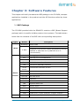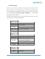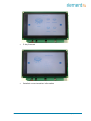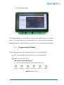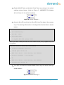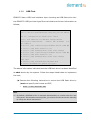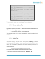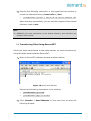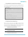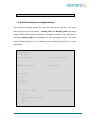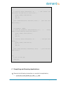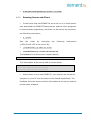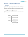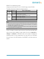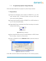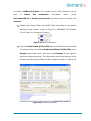
1
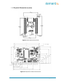
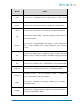
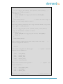
Embedded Display Module EDM6070AR-01 Atmel AT91SAM9X35 Based Single Board Computer BY User Manual Version 1.0 Dated: 3rd December 2013 Revision History: Version Date Description 1.0 03/12/2013 Original Version Table of Contents Chapter 1: Product Overview............................................. 1 1.1 Introduction .............................................................1 1.2 Kit Contents .............................................................3 1.3 Expansion Board Interfaces ........................................4 1.4 Core Board Interfaces ................................................4 1.5 System Block Diagram ...............................................6 1.6 Physical Dimensions (mm) .........................................7 Chapter 2: Hardware Features .......................................... 8 2.1 Processor .................................................................8 2.2 On-Board Memory .....................................................8 2.3 On-Board Interfaces ..................................................8 2.4 Others .....................................................................9 2.5 Operational Parameters..............................................9 Chapter 3: Software Features.......................................... 10 3.1 BSP Package........................................................... 10 3.2 Example Applications ............................................... 11 3.3 API Functions ......................................................... 12 Chapter 4: 4.1 Demonstration and Test Functions................. 16 Smart Home Automation Demo................................. 16 4.1.1 Demo Features .................................................. 17 4.1.2 Programming the demo ...................................... 21 4.2 System Setup ......................................................... 23 4.3 Testing Features...................................................... 24 4.3.1 Touchscreen Test ............................................... 24 4.3.2 LCD Colour Test ................................................. 24 4.3.3 LCD Backlight Test ............................................. 25 4.3.4 Ethernet Test .................................................... 25 4.3.5 Serial Interface (RS232) Test .............................. 26 4.3.6 CAN Bus Test .................................................... 27 4.3.7 RS485 Bus Test ................................................. 28 4.3.8 USB Test........................................................... 29 4.3.9 RTC Test ........................................................... 30 4.3.10 TF Card Test .................................................. 31 4.3.11 LED Test ....................................................... 32 4.3.12 Buzzer Test ................................................... 32 4.3.13 GPIO Test...................................................... 32 4.3.14 Button Test ................................................... 33 4.3.15 Screen Capture Test ....................................... 34 4.3.16 Audio Test ..................................................... 34 4.3.17 Watchdog Test ............................................... 35 4.3.18 Telnet Test .................................................... 35 4.3.19 Mounting NFS (Network File System)................ 38 4.4 Transferring Files Using SecureCRT ............................ 39 4.5 Transferring Files Using Network Protocol ................... 40 4.6 Linux QT Demonstration........................................... 42 Chapter 5: Development Environment and System Compilation……………… ....................................................... 44 5.1 Building a Cross Compilation Environment .................. 44 5.2 System Compilation ................................................ 45 5.3 Uncompressing Files ................................................ 45 5.4 Making a Bootstrap ................................................. 46 5.5 Making a U-boot ..................................................... 47 5.6 Making a Kernel ...................................................... 47 5.7 Making a File system Image ..................................... 48 Chapter 6: System Customization.................................... 49 6.1 Kernel Customisation ............................................... 49 6.2 File system Customisation ........................................ 51 6.3 Simple Driver Modules in Kernel ................................ 52 6.4 Using Makefile to Associate Drivers with Kernel ........... 55 6.5 Compiling and Downloading Drivers........................... 55 6.6 Brief Introduction to Applications .............................. 56 6.7 Compiling and Running Applications .......................... 57 6.8 Common Functions .................................................. 58 6.9 Linux Multi-Thread Programming ............................... 59 6.10 Linux Network Programming..................................... 61 6.11 Compiling Server .................................................... 64 6.12 Compiling Client...................................................... 64 6.13 Running Server and Client ........................................ 65 Chapter 7: 7.1 Updating the Linux System ............................ 66 Images and the Programming Tool ............................ 66 7.1.1 Programming System Image Automatically ........... 67 7.1.2 Programming System Image Manually .................. 69 7.2 Preparations ........................................................... 69 7.3 Programming Image Files......................................... 71 Chapter 8: Appendix A: Common u-boot Instructions ..... 76 Chapter 1: Product Overview 1.1 Introduction The EDM6070AR-01 is an ARM based Single Board Computer (SBC), designed & developed by element14. It comprises of a 7” LCD display and touch screen assembly, integrated with multi-functional embedded hardware based on Atmel’s ARM9 AT91SAM9X35 industrial processor. The EDM6070AR-01 is a fully integrated Embedded Display Module solution for a variety of embedded control HMI applications, ready to drop into your product with negligible integration effort, OR to just wrap an enclosure around, add a software application and become your finished product. The EDM6070 is designed to fulfil the different requirements of various HMI applications including: Industrial control terminals Intelligent instruments Data acquisition and analysis Medical products Network terminals. The EDM6070AR-01 consists of three parts: a MINI6935 CPU core module, an expansion board, and a 7” TFT LCD (800×480) with resistive touch screen. MINI6935 CPU module is an ARM embedded board, integrated with the ATMEL ARM926EJ-S-based processor AT91SAM9X35, operating at 400MHz frequency. The board has 128MB DDR2 SDRAM, 256MB NAND Flash, 4MB DataFlash, 4KB Two-wire EEPROM. Page | 1 The Base Board expands the rich set of connectivity and user interface peripherals of the Atmel AT91SAM9X35 including Ethernet and CAN interface. The board also has a TFT touch screen LCD interface, USB hosts/device, Buzzer, RS232, RS485, Audio, GPIOs and an SD card interface to allow for large storage capabilities. LCD Touch screen Display is a 4-wire resistive touch screen TFT LCD display with a display resolution of up to 800x480 with 24-bit colour depth. The EDM6070AR-01 includes Linux BSP and supports the Linux QT GUI (Graphical User Interface) and multiple file systems like, FAT, NTFS etc. It is also supplied with a Smart Home demo application (include smart-led controller, weather controller, video) and a number of example applications to give you a quick and easy start. Page | 2 1.2 Kit Contents The EDM6070AR-01 SBC is packed with the items listed below: MINI6935 CPU Process Board based on AT91SAM9X35 MCU Expansion Base Board 7” Touchscreen LCD Display Product DVD/CD includes BSP, demo application & technical documentation. Optional Accessories (must be purchased separately): Serial Cable (Cross Over Female-to-Female) Ethernet Cable MicroUSB Cable Serial Interface Adapter Power Adapter ([email protected]) Page | 3 1.3 Expansion Board Interfaces Figure 1: Base Board Interface with Mounted CPU Module 1.4 Core Board Interfaces Figure 2: MINI6935 CPU Module (Front View) Page | 4 Figure 3: MINI6935 CPU Module (Rear View) Page | 5 1.5 System Block Diagram AT91SAM9X35 GPIO ISO Data RS485 ISO K9F2G08U0 NAND CAN 2.0 ISO AT24C04BN TWI MAC DM916 800x480 RGB 7 LCD MT47H64M16HR AT25DF321 32MB DDR2 RTC Watchdog Key SD CARD Reset USB Host USB Device Audio RS232 Debug Port Figure 4: System Block Diagram Page | 6 1.6 Physical Dimensions (mm) Figure 5: Mini6935 Dimensions Figure 6: Expansion Board Dimensions Page | 7 Chapter 2: Hardware Features 2.1 Processor Atmel AT91SAM9X35 ARM9 32-bit processor, 400MHz 16KB data cache, 16KB instruction cache, memory management unit 64KB internal ROM and 32KB internal SRAM 2.2 On-Board Memory 128MB DDR2 SDRAM 256MB NAND Flash 4MB DataFlash 2.3 On-Board Interfaces 7” TFT LCD display, resolution of 800x480 with 24-bit colour depth 10/100Mbps Ethernet interface, using a DM9161CIEP chip, extendable via expansion board RS232 interface, 1 RS485 interface, 1 CAN interface USB Host high-speed interface USB Device interface Three GPIO Input interfaces Four GPIO Output interfaces Audio output interface, supporting MP3 playback Debugging Interface, extendable via expansion board TF card slot Page | 8 2.4 Others I/O interface LED indicator, 2 LED power indicators Buzzer I/O button Reset button RTC (no battery by default) Watchdog 2.5 Operational Parameters Operating Temperature: -10 °C ~ 70 °C Operating Humidity: 0% ~ 90% (Non-condensing) Power Supply: [email protected] Electrical Standards: CE, FCC and CCC Product Dimensions: 181mm x 120mm Page | 9 Chapter 3: Software Features This chapter will briefly introduce the BSP package in the CD-ROM, example applications installed in the product and the API functions called by these applications. 3.1 BSP Package The CD-ROM provided with the EDM6070 contains a BSP (Board Support package) which is used for building custom Linux systems. The table shown below lists the contents of the BSP with corresponding descriptions. Types Names Bootstrap Description Serial Flash Serial Flash BIOS U-Boot Supports kernel and file system programming through SAM-BA or USB flash drive (USB flash drive is recommended) Serial RTC Ethernet Debugging and COM2 serial interface on CPU Internal RTC of AT91SAM9X35 10/100M Ethernet driver Flash NAND Flash and DataFlash driver LCD LCD driver, 800x480 resolution Touch Touchscreen controller on CPU Screen Device Drivers USB Host USB Host driver Watchdog Built-in watchdog driver SD Card SD card driver CAN Bus CAN bus RS-485 RS-485 bus LED System status LED BEEP Buzzer driver Audio WM8731EDS audio output driver Button Custom user button driver GPIO Kernel Linux-2.6.39 GPIO driver, 3 input channels, 4 output channels ROM/CRAM/EXT2/EXT3/FAT/NFS/JFFS2/YAFFS2/UBIFS Page | 10 Types Names Description file systems Root File System UBIFS Readable and writeable file system, supporting compression storage 3.2 Example Applications The Linux system installed in EDM6070 contains multiple example applications under /home/app. Users can use those applications to implement, test or demonstrate various product functionalities. The following block diagram clearly shows the location of each example application in the system. /home/app COM UART Test EVTEST Event Devices Test GPIO GPIO Test LED LED Test BEEP Buzzer Test CAN Test CAN CAN Receiver Test CAN Transmitter Test Figure 7: Example Applications (Directory Structure) Page | 11 3.3 API Functions Before you start to test the product, it is necessary to learn about the API functions used by the example applications. If you need to understand the working principle of an application in detail, read the source code stored under “\02 Linux 2.6 Kit\01 Source Code\app\” in the CD-ROM provided along with EDM6070. The tables listed below will show you the API functions called by some of applications and the relevant information. LED API Function LED_API int led_ctrl (char *name, int onoff); Source ledlib.h Functionalities Turn on or off LEDs Name (LED’s name such asD6, D9 or D13) Parameters onoff (0 for off, 1 for on) Returned Values 0 for success, otherwise failure Examples Buzzer led_ctrl ("D9", 1); API Function BEEP_API int beep_ctrl (char *name, int onoff); Source beeplib.h Functionalities Controls the buzzer to make sound or stop Name (buzzer name, normally there is only one buzzer which is called “beep”) Parameters onoff (0 for off, 1 for on) Returned Values 0 for success, otherwise failure Examples Serial beep_ctrl ("beep", 1); beep_ctrl ("beep", 0); Interface API Function int OpenDev(char *Dev); Source Functionalities com_example.c Enable serial devices and acquire descriptors Page | 12 dev (character string of serial devices, e.g. Parameters “/dev/ttySAC0”) Values more than 0 is a serial file descriptor, less than 0 stands for failure Returned Values com_example.c void set_speed(int fd, int speed); Source Functionalities Parameters Returned Values com_example.c Set the bitrate of serial interfaces fd (serial file descriptor) speed (bitrate, e.g. 15200) None int set_Parity(int fd,int databits,int stopbits,int parity,int flowctrl); Source Functionalities com_example.c Set serial interface data bits, stop bits, parity check and data flow control fd (serial file descriptor) databits (length of data bits) stopbits (length of stop bits) Parameters parity (check type, N for no check, O for odd check, E for even check) flowctrl (switch of hardware data follow control, 1 for enable, 0 for disable) Returned Values 0 for success, otherwise failure size_t read(int fd, const void *buf, size_t nbytes); Source Functionalities unistd.h Called by system to acquire data received on the serial interfaces fd (serial file descriptor) Parameters buf (pointer to the received data) nbytes (data length about to be read, Byte) Returned Values Values less than 0 stands for error, more than 0 stands for received data length (Byte) size_t write(int fd, const void *buf, size_t nbytes); Source Functionalities Parameters unistd.h Called by system to send data through the serial interfaces fd (serial file descriptor) Page | 13 buf (pointer to the data about to be sent) nbytes (length of data about to be sent, Byte) Value of less than 0 stands for an error, more Returned Values than 0 stands for a data length being sent (Byte) int close(int fd); Source unistd.h Functionalities Parameters Called by system to disable the serial interfaces fd (serial file descriptor) Returned Values 0 for success, less than 0 stands for error GPIO API Function int open(const char *path, int oflags); Source gpio_example.c Functionalities Parameters Initialize the GPIO device node Path: /dev/gpio.0 Returned Values oflags: O_RDWR 0 for success, otherwise failure int close(int fildes); Source gpio_example.c Functionalities Parameters Release GPIO fildes: open returned file descriptor Returned Values 0 for success, otherwise failure ioctl(fd, GPIO_GET_VALUE, pin); Source gpio_example.c Functionalities Read the logic level of the input pin Pin (GPIO pin name, such as GPIO_PB15) Parameters fd (GPIO device descriptor) Returned Values Return level value in digit 0 or 1 ioctl(fd, GPIO_SET_PIN, pin); Source Functionalities Parameters Returned Values gpio_example.c Allow the output pin provide a high level output Pin (GPIO pin name, such as GPIO_PD18) None Page | 14 ioctl(fd, GPIO_CLR_PIN, pin); Source Functionalities Parameters Returned Values gpio_example.c Allow the output pin to provide a low level output Pin (GPIO pin name, such as GPIO_PD18) None Page | 15 Chapter 4: Demonstration and Test Functions This chapter will introduce to the Smart Home Automation demo application and how to use the example applications contained in the system to implement functionality tests of the EDM6070, as well as a demonstration of the LinuxQT graphics interface. 4.1 Smart Home Automation Demo A Smart Home System demo application has been provided with the EDM6070. This demo application enables EDM developers to quickly and easily jumpstart their embedded Linux application development — without first having to set up their development environment. Smart Home automation demo features a QT GUI application with several custom widgets, including: Climate Control Light control Thermostat control Page | 16 Video player 4.1.1 Demo Features This demo showcases the control of various house functions including heating, lighting, security and a media player. The major functions are expounded upon below: 4.1.1.1 Climate Control This application allows the user to control the temperature and humidity throughout the house on a room by room basis. There is also a display indicating the current weather which can be activated to display extra information: Page | 17 5 day forecast Detailed current weather information Page | 18 Pulse-doppler radar weather display The weather information is updated via the internet and as such the EDM6070 requires an internet connection in order to provide this functionality 4.1.1.2 Lighting Control Page | 19 The lighting application allows the user to set the light levels in each room independently. The application emulates a standard dimmer switch making the software both intuitive and user friendly 4.1.1.3 Security The security application allows the EDM6070 to connect to cameras and door locks at any user defined entrance. This allows the user to monitor the entrance and either allow or deny access to the property Page | 20 4.1.1.4 Media Player The Media application will allow the user to play audio into any connected room. The audio files can be streamed from internet radio, terrestrial / satellite radio or a local media server such as a PC or networked storage. 4.1.2 Programming the demo Follow the steps below to program the demo onto the EDM6070 1) Set up a HyperTerminal as shown in 4.2 System Setup. 2) Copy the demo files from: \02 Linux 2.6 kit\00 image\ on the CD to the root directory of a MicroSD card Figure 8: Demo Files Page | 21 3) Enable NAND Flash and disable Serial Flash according to the switch settings shown below: (refer to Figure 2: MINI6935 CPU Module (Front View) for the switch location) Figure 9: Switch Settings 1 4) Insert a MicroSD card into the MicroSD slot of the board, then power it up. The booting information in the HyperTerminal window is shown below: RomBOOT Start AT91Bootstrap... Init DDR... Done! Downloading image... *** f_open, File name: [logo]: error! When you hear a beep and see the information below, the programming has completed. NAND write: device 0 offset 0x0, size 0x260000 [nand_write_skip_bad] return rval 2490368 bytes written: OK NAND erase: device 0 offset 0xc00000, size 0x6e00000 Erasing at 0x79e0000 -- 100% complete. OK NAND write: device 0 offset 0xc00000, size 0x5540000 89391104 bytes written: OK 5) Turn OFF the board and enable NAND Flash using the switch settings shown below: Figure 10: Switch Settings 2 Page | 22 6) Turn the board on again and wait a few moments. The smart home demo UI should be displayed on the screen 4.2 System Setup Prior to commencing various features tests for EDM6070, you should first configure a HyperTerminal according to the parameters shown in the figure below; Figure 11: Configuring HyperTerminal After setting up the HyperTerminal, connect EDM6070 to your PC via a serial interface adapter and a serial cable, and then power on the board. You can see boot-up information in the HyperTerminal window. Page | 23 4.3 Testing Features Note: Each instruction has been proceeded by a pencil “” to prevent confusion caused by any long instructions that occupy more than one line in the context. Please note that there are SPACES in some of the following instructions; Missing any SPACE will lead to failure when running an application. 4.3.1 Touchscreen Test 7) Execute the following instruction to run the touch screen calibration program; [root@Mini69X5:/]# ts_calibrate And then press the “+” symbols that appear on the screen with your fingers or a compatible stylus to complete calibration; 8) Execute the following instruction to test the touchscreen; [root@Mini69X5:/]# ts_test Select Drag or Draw on the screen to test the dragging and drawing functionalities. You can exit the example application by pressing Ctrl+C on your PC’s keyboard. 4.3.2 LCD Colour Test Upon execution of the following instruction the LCD will display the 3 elementary RGB colours separately and together. [root@Mini69X5:/]# /home/app/lcd Page | 24 4.3.3 LCD Backlight Test 1) Execute the following instruction to adjust the backlight. The brightness value can be any integer from 1 to 10 inclusive. In this example the brightness has been set to 5 [root@Mini69X5:/]# bl_adjust SET 5 2) Execute the following instruction to turn off the backlight; [root@Mini69X5:/]# bl_adjust OFF 3) Execute the following instruction to turn on the backlight; [root@Mini69X5:/]# bl_adjust ON 4.3.4 Ethernet Test 1) Execute the following instruction to set the IP address of the EDM6070 to 192.192.192.200; [root@Mini69X5:/]# ifconfig eth0 192.192.192.200 2) Execute the following instruction to test network connection; [root@Mini69X5:/]# ping 192.192.192.105 3) Execute the following instruction to set the gateway address; [root@Mini69X5:/]# route add default gw <Your_GateWay_Addr> For example: [root@Mini69X5:/]#route add default gw 192.192.192.101 4) Execute the following instruction to set DNS address; [root@Mini69X5:/]# echo “nameserver <Your_DNS_Addr>” > /etc/resolv.conf For example: [root@Mini69X5:/]# echo "nameserver 202.96.128.166" >/etc/resolv.conf Page | 25 Note: The IP addresses above are only examples. Make sure the IP address of the EDM6070 is in the same network range as your PC. After all the settings are complete, execute a PING command to test the network connection. The HyperTerminal window will show similar information to that which follows: PING 192.192.192.105 (192.192.192.105): 56 data bytes 64 bytes from 192.192.192.105: icmp_seq=0 ttl=64 time=0.5 ms 64 bytes from 192.192.192.105: icmp_seq=1 ttl=64 time=0.3 ms 64 bytes from 192.192.192.105: icmp_seq=2 ttl=64 time=0.3 ms 64 bytes from 192.192.192.105: icmp_seq=3 ttl=64 time=0.3 ms --- 192.192.192.105 ping statistics --7 packets transmitted, 7 packets received, 0% packet loss round-trip min/avg/max = 0.3/0.3/0.5 ms ~ $ To terminate the Ethernet test, press Ctrl+C on your keyboard. 4.3.5 Serial Interface (RS232) Test EDM6070 provides 3 serial interfaces - ttyS2(RS232), ttyS0(RS485) and ttyS6 ( RS232 ) as debugging interfaces. Execute the following instruction to test these serial interfaces. [root@Mini69X5:/home/app]# ./com -d /dev/ttyS2 -s 1234567890 -b 115200 Table 1: Parameters Used in Instructions Parameters Descriptions -d Serial device node used to specify a serial interface -s Character string to be sent -b Set bitrate -f Enable hardware flow control Page | 26 4.3.6 CAN Bus Test Connect your EDM6070 to another EDM6070 or a device with a CAN bus according to the figure shown below; Figure 12: CAN Bus Connection Note: The jumper JP13 in the figure shown above is shorted in order to enable 120R terminal resistor. After connection is complete, execute the following instructions to test the CAN bus; [root@Mini69X5:/]# cd /home/app/can/ [root@Mini69X5:/]# ifconfig can0 down [root@Mini69X5:/]# ip link set can0 type can bitrate 800000 (Set bitrate to 800k) [root@Mini69X5:/]# ip -details link show can0 (View can0 configurations) [root@Mini69X5:/]# ifconfig can0 up (Enable can0) [root@Mini69X5: /home/app/can/]# ./candump can0 (Receiving mode) [root@Mini69X5: /home/app/can/]# ./cansend can0 "5A1#1122334455667788" (Send standard frames) [root@Mini69X5: /home/app/can/]# ./cansend can0 "1F334455#1122334455667788" (Send extended frames) To terminate the CAN bus test, press Ctrl+C on your keyboard. Page | 27 4.3.7 RS485 Bus Test The device corresponding to RS485 interface is /dev/ttyS0. Similar to the CAN bus test, the transceiving test over this bus needs another EDM6070 or RS485-enabled device; connect them according to the figure shown below; Figure 13: RS485 Bus Connection Note: For long-distance transmission, the jumper JP12 needs to be shorted. Execute the following instruction to test the RS485 bus connection; [root@Mini69X5: /home/app/]# ./com -d /dev/ttyS0 To terminate the RS485 bus test, press Ctrl+C on your keyboard. Page | 28 4.3.8 USB Test EDM6070 has a USB host interface. Upon inserting an USB flash drive into the EDM6070 USB port the HyperTerminal window will show information as follows; usb 1-1: USB disconnect, address 2 usb 1-1: new full speed USB device using at91_ohci and address 3 usb 1-1: configuration #1 chosen from 1 choice scsi2 : SCSI emulation for USB Mass Storage devices scsi 2:0:0:0: Direct-Access Generic USB SD Reader 0.00 PQ: 0 ANSI: 2 sd 2:0:0:0: [sda] 7744512 512-byte hardware sectors (3965 MB) sd 2:0:0:0: [sda] Write Protect is off sd 2:0:0:0: [sda] Assuming drive cache: write through sd 2:0:0:0: [sda] 7744512 512-byte hardware sectors (3965 MB) sd 2:0:0:0: [sda] Write Protect is off sd 2:0:0:0: [sda] Assuming drive cache: write through sda: sda1 sd 2:0:0:0: [sda] Attached SCSI removable disk sd 2:0:0:0: Attached scsi generic sg1 type 0 The above information indicates that the USB flash drive has been identified as sda1 device by the system. Follow the steps listed below to implement the test; 1) Execute the following instruction to mount the USB flash drive to /mnt and specify the format as VFAT; mount –t vfat /dev/sda1 /mnt Note: By default, USB flash drive is mounted automatically to /media under the root file system. If automatic mounting fails, you need to mount the device manually by using the above instructions. Page | 29 2) Execute the following instruction to view the contents of the USB flash drive; root@Mini69X5:/mnt/usbhd-sda1]# ls 3) Execute the following instructions to un-mount the USB flash drive; [root@Mini69X5:/mnt/usbhd-sda1]# cd .. [root@Mini69X5:/mnt]# umount usbhd-sda1 4.3.9 RTC Test RTC is used to store and recover the system clock. Follow the steps listed below to test the RTC; 1) Execute the following instruction to view the current system clock; [root@ Mini69X5:/]# date The system clock readout is shown below; Thu Nov 27 11:48:02 UTC 2013 2) Execute the following instructions to set system clock to 16:43, Nov. 29th, 2013; [root@Mini69X5:/]# date –s 112916432013 The HyperTerminal shows information as follows; Thu Nov 29 16:43:00 UTC 2013 3) Execute the following instruction to write system clock into RTC; [root@ Mini69X5:/]# hwclock –w 4) Execute the following instruction to view RTC clock; [root@ Mini69X5:/]# hwclock -r The HyperTerminal shows information as follows; Thu Nov 29 16:43:00 UTC 2013 Page | 30 5) Execute the following instructions to update system clock with the clock information stored in RTC, and them view the system clock; [root@ Mini69X5:/]# hwclock -s [root@ Mini69X5:/]# date The updated system clock is shown below; Thu Nov 29 16:43:45 UTC 2013 Note: RTC can work properly as long as there is always a battery supplying power; Ensure an R1220 battery is installed. 4.3.10 TF Card Test Insert a microSD card into the microSD card slot of EDM6070, the HyperTerminal shows information as follows; [root@Mini69X5:/]# mmc1: new SD card at address 0002 mmcblk0: mmc1:0002 N/A 489 MB mmcblk0: p1 The above information indicates that card has been defined as mmcblk0p1 device. Follow the steps listed below to implement the test; 1) Execute the following instruction to mount the card to /mnt and specify the format as VFAT; [root@Mini69X5:/]# mount -t vfat /dev/mmcblk0p1 /mnt/ 2) Execute the following instructions to view the contents of the card; [root@Mini69X5:/]# cd /mnt/ [root@Mini69X5:/mnt]# ls 3) Execute the following instructions to un-mount the card; root@Mini69X5:/mnt]# cd / [root@Mini69X5:/]# umount /mnt/ Page | 31 4.3.11 LED Test EDM6070 has 2 LED indicators, among them the D2 is a system status LED. The following steps are the test for D1 (PB18) LED; 1) Execute the following instruction to test LED D1 by running an application; [root@Mini69X5:/]# /home/app/led D1 will be blinking alternately at two different frequencies; 2) Execute the following instruction to turn OFF a single LED; [root@Mini69X5:/]# echo '0' >/sys/class/leds/d1/brightness 3) Execute the following instruction to turn ON a single LED; [root@Mini69X5:/]# echo '1' >/sys/class/leds/d1/brightness 4.3.12 Buzzer Test 1) Test by running an application; [root@Mini69X5:/]# /home/app/beep The buzzer will make a single sound; 2) Instruct the buzzer to make continues sound; [root@Mini69X5:/]# echo '1' >/sys/class/leds/beep/brightness 3) Instruct the buzzer to stop making sound; [root@Mini69X5:/]# echo '0' >/sys/class/leds/beep/brightness 4.3.13 GPIO Test The GPIO test program constantly reads the input interface at a 500ms interval and control the data receiving on output interface. Execute the following instruction to implement the test; Page | 32 [root@Mini69X5:/]# /home/app/gpio If the test is successful, the HyperTerminal window shows information as follows; --------------------------------------* MINI69X5 GPIO Demo * --------------------------------------GPIO_PB15 INPUT 1 GPIO_PD16 INPUT 1 GPIO_PD17 INPUT 1 GPIO_PD18 OUTPUT 0 GPIO_PD18 OUTPUT 0 GPIO_PD18 OUTPUT 0 GPIO_PD18 OUTPUT 0 4.3.14 Button Test Execute the following instruction to test the button SW1 on the EDM6070; [root@Mini69X5:/]# /home/app/evtest /dev/event0 The HyperTerminal window shows information as follows; Input driver evdev: (EVIOCGBIT): Suspicious buffer size 511, limiting output to 64 bytes. See http://userweb.kernel.org/~dtor/eviocgbit-bug.html version is 1.0.0 Input device ID: bus 0x19 vendor 0x1 product 0x1 version 0x100 Input device name: "gpio-keys" Supported events: Event type 0 (Sync) Event type 1 (Key) Event code 278 (BackBtn) Press SW1, the HyperTerminal window shows information as follows; Page | 33 Event: time 1167614678.630509, type 1 (Key), code 278 (BackBtn), value 1 Event: time 1167614678.630529, -------------- Report Sync -----------Event: time 1167614678.826399, type 1 (Key), code 278 (BackBtn), value 0 Event: time 1167614678.826412, -------------- Report Sync -----------Event: time 1167614679.430801, type 1 (Key), code 278 (BackBtn), value 1 Event: time 1167614679.430817, -------------- Report Sync -----------Event: time 1167614679.668320, type 1 (Key), code 278 (BackBtn), value 0 To terminate the button test, press Ctrl+C on your keyboard. 4.3.15 Screen Capture Test Execute the following instruction to capture the contents displayed on the LCD and save it as a jpg image; [root@Mini69X5:/]# fbcat /dev/fb0 Figure.jpg The captured images will be saved automatically under the system’s root directory. 4.3.16 Audio Test The system contains an open-source audio player “madplay” by default which supports MP3 playback. Insert headphones into the 3.5mm audio output jack on EDM6070, and then execute the following instruction to implement a test; [root@Mini69X5:/]# madplay /home/mp3/music.mp3 If you hear music, the audio functionality is working properly. To view help information, execute instruction “madplay –h”. Page | 34 4.3.17 Watchdog Test Execute the following instruction to run the watchdog test program; [root@Mini69X5:/]# /home/app/watchdog The HyperTerminal window shows information as follows; Watchdog open success usage: [a] -- Feed dog [q] -- Quit without stop watchdog [e] -- Quit and stop watchdog 4.3.18 Telnet Test Connect EDM6070 to your LAN by using a RJ45 network cable, and then follow the steps listed below to implement the test; 1) Open a command prompt, the method for doing this can vary depending on your version of windows. Note: For Windows XP: click start, then run and in the dialogue box that appears type “cmd” and hit enter on your keyboard. For Windows 7: click start then enter “cmd” into the search box then hit enter on your keyboard. You will then be presented with a window as follows. Page | 35 Figure 14: Command Prompt Window 2) Type “ping 192.192.192.211” to test the network connection (the default IP address of the EDM6070 is 192.192.192.211) as shown below; Figure 15: Network Test After Completion 3) Type “telnet 192.192.192.211” to initiate a telnet session as shown below; Page | 36 Figure 16: Telnet Session Initialization 4) Type the default username “root” and leave the password blank as shown below; Figure 17: Telnet Log In Now you have logged in to the telnet session successfully, to exit the session, type “exit”. Note: By default, telnet service is disabled under Windows 7. To enable the service select Control Panel > Programs > Programs and Features > Turn Windows features on or off, and then check “Telnet Client”. The default IP address of EDM6070 is 192.192.192.211. Ensure that the board and your PC are set in the same network segment. Page | 37 4.3.19 Mounting NFS (Network File System) By mounting the NFS (Network File System), users can access the shared directory remotely under a Linux environment. Follow the steps listed below to test the NFS network file system; 1) Log in to the Linux system on your PC as a root user; 2) Add the following line at the end of the file /etc/exports, and then save the changes; /home/nfs *(rw,sync,no_root_squash) /home/nfs: Shared directory on NFS server; mountable by all client terminals no_root_squash:Allow the client terminals which mount the directory to operate as a root user; 3) Execute the following instruction to enable the NFS server; [root@:/]# /etc/init.d/nfs-kernel-server start 4) Check if the NFS server is enabled successfully; [root@:/]# mount -o nolock localhost:/home/nfs /tmp If there is no error reported by system and the information obtained by executing “ls /tmp” is consistent with the contents under the shared directory of the NFS server, the server is functioning properly. 5) Power on EDM6070 and connect it to a PC with a network cable, and then set the IP address for the board in the HyperTerminal window; Make sure the communication between the board and your PC’s Linux system is working properly by executing a PING command; Page | 38 6) Execute the following instruction in the HyperTerminal window to mount the shared directory /home/nfs to /mnt [root@Mini69X5:/]# mount -o nolock 192.192.192.105:/home/nfs /mnt After mounting successfully, you can see the contents of the shared directory under /mnt. Note: EDM6070 has write permission to the shared directory, and therefore any changes will be saved. 4.4 Transferring Files Using SecureCRT Follow the steps listed below to test data transfer via serial interfaces by using Windows-based software SecureCRT; 1) Open a SecureCRT software window as shown below; Figure 18: SecureCRT Window Execute the following instructions in the window; [root@Mini69X5:/]# cd /tmp [root@Mini69X5:/tmp]# rx recvfile 2) Click Transfer > Send XModem on the menu bar to open the following window; Page | 39 Figure 19: File Selection Select a file to be sent and then click send; The HyperTerminal window shows information as follows; Starting xmodem transfer. Press Ctrl+C to cancel. Transferring dataflash_at91sam9g45ekes.bin... 100% 4 KB 0 KB/s 00:00:05 0 Errors [root@Mini69X5:/tmp]# The above information indicates that the file has been received successfully. Note: Serial interfaces work at a relatively low speed, so it is recommended to choose a small file when transferring. 4.5 Transferring Files Using Network Protocol Follow the steps listed below to transfer a large file using the TFTP protocol; Page | 40 1) Put the file to be sent in the HOME directory (e.g. G:\data.bin) and run tftpd.exe (this program can be found under “\02 Linux2.6 Kit\02 Tools\” in the CD-ROM) on your PC; Select Tftp > Configure on the menu bar of the program window, and set the path to Home Directory, and then select Tftp > Start on the menu bar to start TFTP service; 2) Execute the following instruction in the HyperTerminal window to download data.bin file; [root@Mini69X5:/tmp]# tftp -g 192.192.192.71 -r data.bin 3) Execute the following instruction to view the downloaded file; [root@Mini69X5:/tmp]# ls -l The HyperTerminal window shows information as follows; -rw-r--r-- 1 root root 4420 Jan 1 00:44 data.bin The above information indicates that the file has been downloaded successfully. 4) Execute the following instruction to rename the downloaded file as data_send.bin; [root@Mini69X5:/tmp]# mv data.bin data_send.bin 5) Execute the following instruction to upload the file to the HOME directory of your PC; [root@Mini69X5:/tmp]# tftp -p 192.192.192.71 -l data_send.bin 6) Enter the shared directory to view the uploaded file as shown below; Page | 41 Figure 20: Uploaded File The image shown above indicates a successful uploading. 4.6 Linux QT Demonstration When the system is under the shell interactive mode, you can start the Qtopia application by entering the command “qpe”. Then follow the steps listed below; 1) Execute the following instruction in the HyperTerminal window to begin calibration of the touch screen; [root@Mini69X5:/]# ts_calibrate Follow the instructions as they appear on the screen to implement calibration; 2) Execute qpe command to run Qtopia applications; (the file system has to have a QT installed) [root@Mini69X5:/]# qpe Page | 42 The QT interface and system information are shown below; Figure 21: Main QT Interface Figure 22: QT Interface Showing System Information Page | 43 Chapter 5: Development Environment and System Compilation Before getting started with the development on the board, an ARM Linux cross development environment is required. This chapter will take Ubuntu as the example operating system to show you how to build a cross development environment and accomplish system compilation. 5.1 Building a Cross Compilation Environment The CD-ROM provided with the product contains a cross compilation tool “arm-2007q1-10-arm-none-linux-gnueabi-i686-pc-linux-gnu.tar.bz2” under the directory “\02 Linux2.6 Kit\02 Tools\”. Install it step by step as shown below. 1) Put the CD-ROM in your drive. Ubuntu will mount the CD to /media/CD-ROM by default. Execute the following instructions to install the cross compilation tool; mkdir /usr/local/arm tar –jxvf arm-2007q1-10-arm-none-linux-gnueabi-i686-pc-linux-gnu.tar.bz2 –C /usr/local/arm 2) Execute the following instruction to add an environment variable which specifies the path to the cross compilation tool in the system. export PATH=/usr/local/arm/arm-2007q1/bin/:$PATH 3) Execute the following instruction to check if the installation is done; arm-none-linux-gnueabi-gcc –v Page | 44 The HyperTerminal window shows information as follows; Using built-in specs. Target: arm-none-linux-gnueabi … gcc version 4.2.0 20070413 (prerelease) (CodeSourcery Sourcery G++ Lite 2007q1-10) If the version number within the last line is correct, the cross compilation environment has been built successfully. Note: The instruction adding environment variables can be put into the file .bashrc under user directory to allow the system load the variable automatically each time when it boots up. 5.2 System Compilation The compilation of the operating system can be accomplished in 5 steps – uncompressing files, making a Bootstrap, making a U-boot, making a kernel and making a file system image. This section will introduce these steps in detail. 5.3 Uncompressing Files The system source code can be found under \02 Linux 2.6 Kit\01 Source Code\ in the CD-ROM. Execute the following instructions to uncompress it under a Linux system. root@LINUXSERVER:~# mkdir embest root@LINUXSERVER:~# cd embest/ root@LINUXSERVER:~/embest# cp /media/cdrom/02\ Linux\ 2.6\ Kit/01\ SourceCode/bootloader/ AT91Bootstrap-5series_1.2.tar.bz2 ./ root@LINUXSERVER:~/embest# cp /media/cdrom/02\ Linux\ 2.6\ Kit/01\ Page | 45 SourceCode/bootloader/ u-boot-at91sam9x35.tar.bz2 ./ root@LINUXSERVER:~/embest# cp /media/02\ Linux\ 2.6\ Kit/01\ Source Code/kernel / linux-2.6.39.tar.bz2 ./ root@LINUXSERVER:~/embest# cp /media/cdrom/02\ Linux\ 2.6\ Kit/01\ SourceCode/rfs/ rootfs.tar.bz2 ./ root@LINUXSERVER:~/embest# tar jxvf /media/cdrom/02\ Linux\ 2.6\ Kit/02\ Tools/mkubifstools.tar.bz2 –C /usr/local/bin/ root@LINUXSERVER:~/embest# cp /media/cdrom/02\ Linux\ 2.6\ Kit/02\ Tools/mkimage /usr/local/bin/ root@LINUXSERVER:~/embest# chmod 755 /usr/local/bin/mkyaffs2image /usr/local/bin/mkimage root@LINUXSERVER:~/embest# tar jxvf AT91Bootstrap-5series_1.2.tar.bz2 root@LINUXSERVER:~/embest# tar jxvf u-boot-at91sam9x35.tar.bz2 root@LINUXSERVER:~/embest# tar jxvf linux-2.6.39.tar.bz2 root@LINUXSERVER:~/embest# mkdir rfs; tar jxvf rootfs.tar.bz2 -C rfs Four directories - linux-2.6.39, u-boot-1.3.4, Bootstrap-v1.14 and rfs-qtopia have been generated under the current directory. 5.4 Making a Bootstrap EDM6070 supports boot-up from DataFlash. Execute the following instruction to generate a Bootstrap; root@LINUXSERVER:~/embest# cd AT91Bootstrap-5series_1.2 root@LINUXSERVER:~/embest/ AT91Bootstrap-5series_1.2# make sam9x35_defconfig; cp sam9x35_defconfig .config root@LINUXSERVER:~/embest/ AT91Bootstrap-5series_1.2 # make A Bootstrap file at91sam9x5ek-dataflashcardboot-3.1.bin has been generated under directory “binaries”. Page | 46 5.5 Making a U-boot Execute the following instructions to generate a u-boot; root@LINUXSERVER:~/embest/ u-boot-at91# make at91sam9x5ek_spiflash_config root@LINUXSERVER:~/embest/ u-boot-at91# make A file U-boot.bin has been generated under current directory. Note: An error might occur when using arm-2007q1-10-arm-none-linux-gnueabi-i686-pc-linux-gnu.tar.bz2 to compile u-boot; the use of arm-2011.03-41-arm-none-linux-gnueabi-i686-pc-linux-gnu.tar.bz2 is recommended when encountering any errors. 5.6 Making a Kernel Execute the following instructions; root@LINUXSERVER:~/embest/linux-2.6.39# make at91sam9x5ek_defconfig root@LINUXSERVER:~/embest/linux-2.6.39# make menuconfig root@LINUXSERVER:~/embest/linux-2.6.39# make uImage A kernel file named uImage has been generated under /arch/arm/boot/. Note: If errors occur when executing “make menuconfig”, the most likely cause is the lack of an ncurses library in your PC’s Linux system. Execute “sudo apt-get install libncurses5-dev” to install the library. Page | 47 5.7 Making a File system Image Use the tool mkyaffs2image under the directory \02 Linux 2.6 Kit\02 Tools\ of the CD-ROM to make a file system image by executing the following instruction (suitable for Ubuntu systems only). root@LINUXSERVER:~/embest# mkubifsimage rfs rootfs.ubifs Page | 48 Chapter 6: System Customization In order to satisfy different application requirements of the customers, designers need to make some customisation to the default configuration of the Linux kernel. This chapter will introduce the process of system customization by using some examples. 6.1 Kernel Customisation By default, the kernel source code provides a configuration file saved under arch/arm/configs/at91sam9x5ek_defconfig. Execute the following instructions to enter the configuration menu and then select the drivers you need according to the entries shown in the table below: root@LINUXSERVER:~/embest/linux-2.6.39# make at91sam9x5ek_defconfig root@LINUXSERVER:~/embest/linux-2.6.39# make menuconfig Page | 49 Drivers Paths Serial Device drivers > Character devices > Serial drivers > AT91 / AT32 Interfaces Buttons GPIO LED on-chip serial port support Device drivers > Input device support > Keyboards > GPIO Buttons Device drivers > Misc devices > Device driver for Atmel GPIO devices Device drivers > LED Support > LED Class Support > LED Support for GPIO connected LEDs Device drivers > MMC/SD/SDIO card support > MMC block device SD/MMC driver > Atmel SD/MMC Driver (Atmel Multimedia Card Interface support) Device drivers > USB support > Support for Host-side USB > EHCI HCD USB (USB 2.0) support > OHCI HCD support > USB Mass Storage supportHCD support > USB Mass Storage support RTC Watchdog CAN Bus MACB Graphics Device drivers > Real Time Clock > AT91RM9200 or some AT91SAM9 RTC Device drivers > Watchdog Timer Support > AT91SAM9 watchdog Networking support > CAN bus subsystem support > CAN Device Drivers > Atmel AT91 onchip CAN controller Device drivers > Network device support > Ethernet(10 or 100Mbit) > Atmel MACB support Device drivers > Graphics support > Support for frame buffer devices > AT91/AT32 LCD Controller support Page | 50 Drivers Paths Touch-Screen Input device support > Touchscreens > Atmel Touchscreen Interface Save the changes and execute the instruction below to compile the customized kernel; root@LINUXSERVER:~/embest/linux-2.6.24# make uImage 6.2 File system Customisation The table shown below lists the configuration files required for filesystem customisation, applications’ paths and corresponding notes; Configuration List Paths Driver Modules /lib/modules/2.6.39/ Driver Module Mounting /etc/init.d/S50modules Network Address /etc/network/interfaces.eth0 Command Line Prompt Name /etc/hostname User Program Auto Running /etc/init.d/S60evnset Environment Variables /etc/profile Touch-Screen Coordinate Files /etc/pointercal udev Rules /etc/udev Notes Store driver module ko Add it to the end of file Page | 51 LCD Backlight Brightness /etc/bl_adjust.conf User Testing Applications /home/app 6.3 Simple Driver Modules in Kernel Drivers are running under kernel mode and can drive hardware directly. They provide a series of interfaces to be called by applications so as to control devices. The table shown below is an example of driver modules that are simple but include most of the interfaces. /* File: device_drv.c */ #include <linux/kernel.h> #include <linux/module.h> #include <linux/init.h> #include <linux/input.h> #include <linux/miscdevice.h> #include <asm/io.h> #include <asm/uaccess.h> #define DEVICE_NAME "demo" /* common head files used by driver */ /* device names that generate nodes /dev/demo after mounting successfully */ static int result = 0; static int device_open(struct inode *inode, struct file *file) /* implement open operation */ { result = 0; /* initiate result */ return 0; } static ssize_t device_read(struct file *filp, char *buffer, size_t count, loff_t Page | 52 *ppos) /* implement read operation */ { int ret = copy_to_user (buffer, (char *)&result, sizeof(result)); /* copy the value of result to buffer */ if (ret < 0) { printk (KERN_ERR "%s: copy_to_user error\n", DEVICE_NAME); return -1; } return sizeof(result); /* return the valid length of buffer, i.e. the storage length of result */ } static ssize_t device_write(struct file *filp, const char *buffer, size_t count, loff_t *ppos) /* write operation*/ { int ret = copy_from_user ((char *)&result, buffer, sizeof(result)); /* copy the received data in buffer to result*/ if (ret < 0) { printk (KERN_ERR "%s: copy_from_user error\n", DEVICE_NAME); return -1; } return sizeof(result); } static int device_release(struct inode *inode, struct file *filp) /* close will trigger the function */ { return 0; } static struct file_operations device_fops = /* register interface function for file operation */ { .owner = THIS_MODULE, .open = device_open, .read = device_read, .write = device_write, .release = device_release, }; static struct miscdevice device_miscdev = /* register misc device information */ { .minor = MISC_DYNAMIC_MINOR, .name = DEVICE_NAME, .fops = &device_fops, }; static int __init device_init(void) /* insmod operation will Page | 53 trigger the function */ { int ret; ret = misc_register(&device_miscdev); /*register device */ if (ret) { printk(KERN_ERR "cannot register miscdev on minor=%d (%d)\n", MISC_DYNAMIC_MINOR, ret); goto out; } printk(KERN_INFO DEVICE_NAME " initialized!\n"); return 0; out: return ret; } static void __exit device_exit(void) /* rmmod operation will trigger the function */ { misc_deregister(&device_miscdev); printk(KERN_INFO DEVICE_NAME " removed!\n"); } module_init(device_init); module_exit(device_exit); MODULE_LICENSE("GPL"); /* protocol used by driver modules */ MODULE_DESCRIPTION("Linux Driver Demo"); /* driver module description */ Page | 54 6.4 Using Makefile to Associate Drivers with Kernel Driver files have to be associated with the kernel by a Makefile before they can be compiled and loaded. The following table shows the source code of the provided Makefile. # File: Makefile ifneq ($(KERNELRELEASE),) obj-m := device_drv.o # driver file with extension name .o other than .c; by default .c files will be searched and compiled automatilly else KERNELDIR ?= ~/embest/linux-2.6.39 # specify the path of kernel source code, note that the path must be the location where you save the code PWD := $(shell pwd) all: $(MAKE) -C $(KERNELDIR) M=$(PWD) modules clean: rm -rf *.o *~ core .depend .*.cmd *.ko *.mod.c .tmp_versions Module.symvers modules.order device_drv.ko endif 6.5 Compiling and Downloading Drivers Before you start to compile drivers using “make” command, the kernel source code should be compiled first. After compiling successfully, you can download the generated file device_drv.ko to the board, and then execute the following instructions and see the feedback from the system. [root@Mini69X5:/]# insmod device_drv.ko demo initialized! [root@Mini69X5:/]# ls /dev/demo /dev/demo [root@Mini69X5:/]# rmmod device_drv.ko Page | 55 demo removed! 6.6 Brief Introduction to Applications The previous example shows the execution process of drivers. You might notice that only two functions – device_init and device_exit have been called, while others remain unused in the above process. The interfaces in structure device_fops are intended for the application layer. The table shown below will give you an example of the basic structure of a Linux application. /* File: demo.c */ #include <stdio.h> #include <fcntl.h> #include <string.h> #define dev "/dev/demo" /* head file being called */ /* demo file node */ int main (void) { int fd; int err = 0; int value; fd = open (dev, O_RDWR); /* open file node, readable and writable */ if (fd < 0) { fprintf (stderr, "open fail\n"); err = 1; goto out; } Page | 56 if (read (fd, &value, sizeof(value)) < 0) { /* read function that calls driver; the read value t is save in value */ fprintf (stderr, "read error\n"); err = 1; goto out; } printf ("read before write, value=%X\n", value); /* print read value before writing */ int writeValue = 0x5E7F; if (write (fd, &writeValue, sizeof(writeValue)) < 0) { /* writing 0x5E7F to driver module by calling write function */ fprintf (stderr, "write error\n"); err = 1; goto out; } if (read (fd, &value, sizeof(value)) < 0) { /* read again after writing */ fprintf (stderr, "read error\n"); err = 1; goto out; } printf ("read after write, value=0x%X\n", value); /* print read value after writing */ out: if (fd > 0) close (fd); return err; } 6.7 Compiling and Running Applications 1) Execute the following instruction to compile the application; # arm-none-linux-gnueabi-gcc demo.c -o demo Page | 57 The generated executable file named demo is the application we need; 2) Execute the following instruction to download it to the board; [root@Mini69X5:/]# insmod device_drv.ko System feedback is shown below; demo initialized! 3) Execute the following instruction to run the application; [root@Mini69X5:/]# ./demo Running information is shown below; read before write, value=0 read after write, value=0x5E7F 6.8 Common Functions The following three functions are commonly used by the driver layer to control the GPIO; Functions Notes int at91_set_gpio_input(unsigned pin, int use_pullup) int at91_get_gpio_value(unsigned pin) int at91_set_gpio_output(unsigned int value) pin, set GPIO as input acquire GPIO input value set GPIO as output Adding the above GPIO code to the appropriate location in the drivers as shown in the following table, can easily implement LED control; Page | 58 Example functions Notes at91_set_gpio_input (AT91_PIN_PC16, set 0); disabled at91_get_gpio_value (AT91_PIN_PC16); PC16 as input, pull-up read the input value on PC16 at91_set_gpio_output(AT91_PIN_PC16, set PC16 to provide high-level 1); output 6.9 Linux Multi-Thread Programming The threads here refer to the multiple tasks created in the user space. These tasks share resources of the same process. It consumes much less cost than common process and features fast context switching. Since the resources are shared by processes, it is necessary to adopt synchronizing measures in order to avoid competition when accessing resources. r/* File: pthread.c */ #include <stdio.h> #include <unistd.h> #include <pthread.h> void read_func(void); void write_func(void); int buffer_has_item = 0; pthread_mutex_t mutex; /* shared resource */ /* mutex lock */ Page | 59 int main(void) { pthread_t reader, writer; /* define process ID pthread_mutex_init(&mutex, NULL); /* */ initiate mutex lock */ pthread_create(&reader, NULL, (void*)&read_func, NULL); /* create process */ pthread_create(&writer, NULL, (void*)&write_func, NULL); pthread_join(reader, NULL); /* wait for end of process */ pthread_join(writer, NULL); return 0; } void write_func(void) { while (1) { pthread_mutex_lock(&mutex); /* enable lock, other processes will be locked */ if (buffer_has_item == 0) { printf("create a new item\n"); buffer_has_item = 1; } pthread_mutex_unlock(&mutex); /* disable lock, other process will be unlocked */ } } void read_func(void) { while (1) { pthread_mutex_lock(&mutex); if (buffer_has_item == 1) { Page | 60 printf ("destroy item\n"); buffer_has_item = 0; } pthread_mutex_unlock(&mutex); } } Execute the following instruction to implement the compilation. 6.10 # arm-none-linux-gnueabi-gcc pthread.c -o pthread_demo -lpthread Linux Network Programming Linux network programming generally can be implemented based on UDP and TCP protocols. UDP is a connectionless transport protocol that provides simple, unreliable and message-oriented services; TCP is a reliable, connection-oriented and byte-stream-based transport protocol. The following examples are a simple TCP server and a client. Server: monitors the connection initiated by the client and sends character string to the client when a connection is created. /* File: server.c */ #include <stdio.h> #include <stdlib.h> #include <errno.h> #include <string.h> #include <sys/types.h> #include <netinet/in.h> #include <sys/socket.h> #include <sys/wait.h> #define MYPORT 3490 /* the port users will be connecting to */ #define BACKLOG 10 /* how many pending connections queue will hold */ main() { int sockfd, new_fd; /* listen on sock_fd, new connection on new_fd */ struct sockaddr_in my_addr; /* local address information */ Page | 61 struct sockaddr_in their_addr; /* connector's address information */ int sin_size; if ((sockfd = socket(AF_INET, SOCK_STREAM, 0)) == -1) { perror (" socket ") ; exit(1) ; } my_addr.sin_family = AF_INET; my_addr.sin_port = htons(MYPORT); my_addr. sin_addr.s_addr = INADDR_ANY; /* auto-fill with local IP */ if (bind(sockfd, (struct sockaddr *)&my_addr, sizeof(struct sockaddr)) == -1) { perror (" bind ") ; exit(1) ; } if (listen(sockfd, BACKLOG) == -1) { perror (" listen ") ; exit(1) ; } while(1) { /* main accept() loop */ sin_size = sizeof(struct sockaddr_in); if ((new_fd = accept(sockfd, (struct sockaddr *)&their_addr, &sin_size)) == -1) { perror (" accept ") ; continue ; } printf("server: got connection from %s\n", inet_ntoa(their_addr.sin_addr)); if (!fork()) { /* this is the child process */ if (send(new_fd, "Hello, world!\n", 14, 0) == -1) perror( " send " ) ; close( new_fd ) ; exit ( 0 ) ; } close(new_fd); Page | 62 while(waitpid(-1,NULL,WNOHANG) > 0); /* clean up child processes */ } } Client: Initiates a connection to the server, receives and prints information sent from the server. /* File: client.c */ #include <stdio.h> #include <stdlib.h> #include <errno.h> #include <string.h> #include <netdb.h> #include <sys/types.h> #include <netinet/in.h> #include <sys/socket.h> #define PORT 3490 /* the port client will be connecting to */ #define MAXDATASIZE 100 /* max number of bytes we can get at once */ int main(int argc, char *argv[]) { int sockfd, numbytes; char buf[MAXDATASIZE] ; struct hostent *he; struct sockaddr_in their_addr; /* connector's address information */ if (argc != 2) { fprintf(stderr,"usage: client hostname\n"); exit (1) ; } if ((he=gethostbyname(argv[1])) == NULL) { /* get the host info */ herror(" gethostbyname ") ; exit (1); } if ((sockfd = socket(AF_INET, SOCK_STREAM, 0)) == -1) { perror( " socket "); exit (1); Page | 63 } their_addr.sin_family = AF_INET; their_addr.sin_port = htons(PORT); their_addr.sin_addr = *((struct in_addr *)he->h_addr); //inet_addr if (connect(sockfd, (struct sockaddr *)&their_addr, sizeof(struct sockaddr)) == -1) { perror(" connect "); exit (1); } if ((numbytes=recv(sockfd, buf, MAXDATASIZE, 0)) == -1) { perror (" recv "); exit (1); } buf[numbytes] = '\0'; printf("Received: %s",buf); close(sockfd) ; return 0; } 6.11 Compiling Server If you have two EDM6070s, you need to compile a server program running on one EDM6070 by executing the following instruction; # arm-none-linux-gnueabi-gcc server.c -o server If you have only one EDM6070, you need to compile a server program running on a PC by executing the following instruction; 6.12 # gcc server.c -o server Compiling Client Execute the following instruction to compile a client program; Page | 64 6.13 # arm-none-linux-gnueabi-gcc client.c -o client Running Server and Client In the event that two EDM6070s are to be run in a client/server pair, download the EDM6070-based server and the client programs to these boards respectively, and then run the server by executing the following instruction; # ./server Run the client by executing the following instructions (192.192.192.105 is the server IP); [root@Mini69X5:/]# chmod 755 client [root@Mini69X5:/]# ./client 192.192.192.105 The feedback from the server is shown below; Received: Hello, world! The information at the server end is shown below; server: got connection from 192.192.192.211 server: got connection from 192.192.192.211 server: got connection from 192.192.192.211 Where there is only one EDM6070, you need to run the server program on your PC and the client on the board respectively. The feedback from the server and the information at the server end are as the same as above. Page | 65 Chapter 7: Updating the Linux System EDM6070 has a Serial Flash and a NAND Flash on board. But the Linux system can only support boot-up from Serial Flash currently. This chapter will introduce in detail how to update the Linux system stored in Serial Flash. 7.1 Images and the Programming Tool The following two figures illustrate how the images are distributed in Serial Flash and NAND Flash. 0x0014C600 Share 0x00058400 U-boot 0x00008400 U-boot Parameter 0x00005000 AT91BootStrap 0x00000000 Figure 23: Images in Serial Flash Page | 66 0x10000000 Share 0x07A00000 UBIFS 0x00C00000 RAMDisk 0x00600000 uImage 0x00000000 Figure 24: Images in NAND Flash Install SAM-BA_2.12.exe Tools\SAM-BA" in the saved under CD-ROM as "\02 well Linux2.6 as Kit\02 the patch sam-ba_2.12_patch2a.exe. After installation is done, a shortcut icon for SAM-BA v2.12 can be found on the desktop of your PC as shown below; Figure 25: SAM-BA Shortcut 7.1.1 Programming System Image Automatically The procedure for automatic programming of system images is much easier than manual method. You only need to copy the relevant Linux images including boot.bin and uboot.bin to the root directory of a card, and insert it into the slot on the board and then power it up. The system will automatically implement programming to Serial Flash and NAND Flash. After the programming process is complete, you just need to reboot the Page | 67 EDM6070 to complete the process. (Images are saved under 02 Linux 2.6 Kit\00 Image of the CD-ROM) The table shown blow contains the images required. Categories Names Tool boot.bin By using tools Images uboot.bin By using tools strap.bin System Images u-boot.bin uImage rootfs.bin Ways to Make Images System image, by renaming at91sam9x5ek-dataflashcardboot-3.1.bin System image, u-boot.bin System image, uImage System image, by renaming UBIFS file system Note: You should erase the boot area of Serial Flash first to make sure that the system will boot from the microSD card. You can find the instructions for erasing a microSD card in Appendix of this manual. If you fail to program the microSD card, format it and try again. SD Formatter is recommended as a formatting tool. If there is already a complete system existing in Serial Flash and NAND Flash, and you just need to update a single image file such as u-boot.bin or uImage or rootfs.bin, a USB flash drive can be used to facilitate the updating process. The only requirement is to copy the file to a USB flash drive and insert it into USB interface of the EDM6070, and then reboot the system. Page | 68 7.1.2 Programming System Image Manually Follow the steps listed below to program a system image manually. 7.2 Preparations 1) Connect the debugging serial interface of EDM6070 to your PC’s serial interface using a female-to-female cross-over serial cable and a serial interface adapter; 2) Connect the MicroUSB interface of EDM6070 to a USB interface on your PC with a MicroUSB cable; 3) Enable NAND Flash and disable Serial Flash according to the switch settings shown below: Figure 26: Switch Settings 1 4) Open a HyperTerminal on your PC and set bitrates to 115200, 8 data bits, no parity, 1 stop bit, no flow control; 5) Power on EDM6070 and run SAM-BA v2.12 to open the window as show below; Figure 27: SAM-BA v2.12 Window If the USB connection between the board and your PC is working properly, Page | 69 an option \USBserial\COMx (x is number of the COM interface) can be seen in Select the connection drop-down menu. Select at91sam9x35-ek in Select your board drop-down menu and then click Connect; 6) Enable both Serial Flash and NAND Flash according to the switch settings shown below; (refer to Figure 2: MINI6935 CPU Module (Front View) for the switch location: Figure 28: Switch Settings 2 7) Click the Serial Flash AT25/AT26 tab in the SAM-BA main window as shown below, and select Enable DataFlash (SPI0 CS0) in the Scripts drop-down menu, and then click Execute on the right to start the enabling process. The information box at the bottom of the window will display the details of the process as shown in Figure 29; Figure 29: Enabling DataFlash Page | 70 8) Select Erase All in the Scripts drop-down menu and then click Execute to erase all the contents in Serial Flash as shown below; Figure 30: Erasing Serial Flash 7.3 Programming Image Files 1) Select Send Boot File in the Scripts drop-down menu of SAM-BA’s main window and then click Execute to open the following window; Figure 31: Selection of Strap.bin Page | 71 Select strap.bin (the at91sam9x5ek-dataflashcardboot-3.1.bin file generated in section 5.4), and click Open to download it to Serial Flash; 2) Enter an address 0x8400 in Address text box of SAM-BA’s main window and click located to the right of the Send File Name text box to open the following window; Figure 32: Selection of U-boot.bin Select u-boot.bin and click open to download it to Serial Flash; 3) Click the NAND Flash tab in SAM-BA main window as shown below, and select Enable NAND Flash in the Scripts drop-down menu, and then click Execute on the right to enable NAND Flash; Page | 72 Figure 33: Enabling NAND Flash 4) Select Enable OS PMECC parameters in the Script drop-down menu and then click Execute to open the following window; Figure 34: ECC Configuration Settings Check Trimffs check-box and keep the rest of options unchanged, and then click OK; 5) Select Erase All in Script drop-down menu of SAM-BA main window, and then click Execute as shown below; Page | 73 Figure 35: Erasing NAND Flash 6) Enter an address 0x0 in Address text box and click on the right of Send File Name text box to open the following window; Figure 36: Selection of uImage Select uImage file and click Open, and then click Send File in SAM-BA main window to download it to NAND Flash; Page | 74 7) Enter an address 0xc00000 in Address text box and click on the right of the Send File Name text box to open the following window; Figure 37: Selection of rootfs.bin Select rootfs.bin file and click Open, and then click Send File in SAM-BA main window to download it to NAND Flash; Reboot the system to finish manually programming system images. Page | 75 Chapter 8: Appendix A: Common u-boot Instructions Erasing Bootstrap sf probe 0; sf erase 0 5000 Erasing u-boot parameter area sf probe 0; sf erase 5000 3000 Erasing u-boot sf probe 0; sf erase 8000 50000 Erasing NAND nand erase.chip NFS root file system setenv bootargs 'console=ttySAC6,115200n81 root=/dev/nfs nfsroot=<NFS_Server_IPAddr>:<NFS_DIRECTORY> ip=<Local_IPAddr>:<NFS_Server_IPAddr>:<Gateway_Addr>:255.255.255. 0::eth0:off' Page | 76