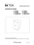
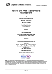
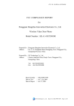
1
ENGINEERING TEST REPORT NUMBER: 10215290EUS1 ON Model No.(s): MB-PRO-MVK, MCU-430F5438A-MVK, AFE-BREAKOUT-MVK, RF-BREAKOUT-MVK, & RF-TCA8418-MVK IN ACCORDANCE WITH: CFR 47, PART 15, SUBPART B, CLASS B VERIFICATION TESTED FOR: Texas Instruments, Inc. 12500 TI Boulevard, M/S 8669 Dallas TX, 75243 TESTED BY: Nemko USA, Inc. 802 N. Kealy Lewisville, Texas 75057-3136 Total Number of Pages: 22 APPROVED BY: DATE: 3-Nov-2011 DATE: 19-Oct-2011 Art Ruvalcaba EMC Engineer TESTED BY: Brian Boyea, EMC Engineer Nemko USA, Inc. authorizes the above named company to reproduce this report provided it is reproduced in its entirety, for use by the company’s employees only. This report must not be used to claim product certification, approval, or endorsement by NVLAP, NIST, or any agency of the Federal Government. Nemko USA, Inc. is a NVLAP accredited laboratory. Any use which a third party makes of this report, or any reliance on or decisions to be made based on it, are the responsibility of such third parties. Nemko USA, Inc. accepts no responsibility for damages, if any, suffered by any third party as a result of decisions made or actions based on this report. This report applies only to the items tested. CFR 47, PART 15, SUBPART B CLASS B VERIFICATION REPORT NO.: 10215290EUS1 EQUIPMENT: EVM Units Table of Contents SECTION 1. SUMMARY OF TEST RESULTS................................................. 3 SECTION 2. EQUIPMENT UNDER TEST (E.U.T.) .......................................... 4 SECTION 3. EQUIPMENT CONFIGURATION ................................................ 6 SECTION 4. CONDUCTED EMISSIONS (MAINS PORTS) ............................. 8 SECTION 5. RADIATED EMISSIONS ........................................................... 13 SECTION 6. MICROWAVE RADIATED EMISSIONS .................................... 18 SECTION 7. TEST METHODS AND BLOCK DIAGRAMS. ........................... 19 SECTION 8. LABELING REQUIREMENTS ................................................... 22 Page 2 of 22 CFR 47, PART 15, SUBPART B CLASS B VERIFICATION REPORT NO.: 10215290EUS1 EQUIPMENT: EVM Units Section 1. Summary of Test Results General: All measurements are traceable to national standards. These tests were conducted on a sample of the equipment for the purpose of demonstrating compliance with CFR 47, Part 15, Subpart B for Class B Digital Devices. These tests were conducted using measurement procedures of ANSI C63.42003. The equipment was tested for conducted emissions from 0.150 MHz to 30 MHz using a 50 microhenry line impedance stabilization network (L.I.S.N.) as described in ANSI C63.4-2003. Peripheral equipment was also operated through a 50 microhenry L.I.S.N. The equipment was tested for radiated emissions from 30 MHz to 1000 MHz in accordance with the requirements of CFR 47, Part 15, Subpart B. Equipment with oscillator frequencies above 108 MHz were tested to the fifth harmonic or in accordance with the requirements of CFR 47, Part 15.33. Frequencies were initially identified in a semi-anechoic chamber. Amplitude measurements were made in a semi-anechoic chamber. Details of the chamber are on file with the FCC and Industry Canada. Abstract: Name of Test Conducted Emissions (Mains port) Radiated Emissions Basic Standard CFR 47, Part 15, Subpart B Para. No. 15.107 CFR 47, Part 15, Subpart B Para. No. 15.109 Results Complies Complies THE FOLLOWING DEVIATIONS FROM, ADDITIONS TO, OR EXCLUSIONS FROM THE TEST SPECIFICATIONS HAVE BEEN MADE: NONE Page 3 of 22 CFR 47, PART 15, SUBPART B CLASS B VERIFICATION REPORT NO.: 10215290EUS1 EQUIPMENT: EVM Units Section 2. Equipment Under Test (E.U.T.) Manufacturer: Texas Instruments, Inc. Name: Development Evaluation Modules Model Number: MB-PRO-MVK, MCU-430F5438A-MVK, AFE-BREAKOUT-MVK, RF-BREAKOUT-MVK, & RF-TCA8418-MVK Serial Number: None Part Number: MB-PRO-MVK, MCU-430F5438A-MVK, AFE-BREAKOUT-MVK, RF-BREAKOUT-MVK, & RF-TCA8418-MVK Production Status: Production E.U.T. Arrival Date: 10/19/11 Description of E.U.T.: Development Evaluation Modules Clock, Oscillator, Highest Frequencies Utilized: 25.0 MHz Justification: The E.U.T. was configured for testing as per typical installation. Position and bundling of cables were investigated to establish maximum amplitude of emissions. Exercise Program: The E.U.T. exercise program used during radiated and conducted testing was designed to exercise the various system components in a manner similar to typical use. The EUT was in the following exercise mode: Powered on running. Page 4 of 22 CFR 47, PART 15, SUBPART B CLASS B VERIFICATION REPORT NO.: 10215290EUS1 EQUIPMENT: EVM Units E.U.T. Photographs: Page 5 of 22 CFR 47, PART 15, SUBPART B CLASS B VERIFICATION REPORT NO.: 10215290EUS1 EQUIPMENT: EVM Units Section 3. Date: 10/19/2011 Company: T.I. Equipment Configuration NEMKO USE ONLY 10215290 JOB # EQUIPMENT CONFIGURATION LIST (HARDWARE/PERIPHERALS): Place an "*" next to EUT and any item that is part of the EUT. Item (A) (B) (C) (D) (E) (F) (G) (H) (I) (J) (K) (L) (M) * * Generic Description Evaluation Module Laptop PowerSupply ¹ FCC ID STATUS 1. FCC DOC 2. FCC A/B Verification Manufacturer T.I. Dell Dell Model No. TMDSDOCK28027 Latitude D610 HA65NS0-00 Serial # Rev. FCC ID Status¹ 20618812117 3. None - (If performing FCC testing, contact lab manager) 4. Certification (include FCC ID in parenthesis) INTER-CONNECTION CABLES: Place an "*" next to EUT and any item that is part of the EUT. Cable Type Item * (1) * USB (2) * Power Supply (3) Manufacturer Generic T.I. EVM TMDSDOCK28343 Page 6 of 22 Ln (m) Term² Shield 1 1 Qty. 1 1 CFR 47, PART 15, SUBPART B CLASS B VERIFICATION REPORT NO.: 10215290EUS1 EQUIPMENT: EVM Units Client Name: T.I. Work Order #: 10215290 Model Number: Date: Test Configuration: 10/196/11 Powered on Transmitting AC 2 B A 1 C Page 7 of 22 CFR 47, PART 15, SUBPART B CLASS B VERIFICATION REPORT NO.: 10215290EUS1 EQUIPMENT: EVM Units Section 4. Conducted Emissions (Mains ports) Purpose: The test is intended to demonstrate the compliance of the Equipment Under Test (E.U.T.) to the limits for conducted disturbance as defined by CFR 47, Part 15, Subpart B, Class B, Paragraph Number 15.107. Specification Limits: Limits for conducted disturbance at the mains ports Frequency Range (MHz) Quasi-peak Limits (dBuV) 0.15 to 0.50 66-56 0.50 to 5.00 56 5.00 to 30.00 60 Average Limits (dBuV) 56-46 46 50 Method of Measurement (Procedure ANSI C63.4-2003): Measurements were made using a spectrum analyzer with 10 kHz RBW, Peak detector. Any emissions that are close to the limit are measured using a test receiver with 9 or 10 kHz bandwidth, CISPR Quasi-Peak detector. See Sections 7 and 8. Page 8 of 22 CFR 47, PART 15, SUBPART B CLASS B VERIFICATION REPORT NO.: 10215290EUS1 EQUIPMENT: EVM Units Test #: CEPV-01 Tested By: Brian Boyea Date of Tests: 10/19/11 Test Conditions: Test Voltage: 120 Vac Temperature: 25˚C Humidity: 45% Test Results: The E.U.T. complies. TEST EQUIPMENT Asset Tag Description Manufacturer Model Serial # Last Cal Next Cal 674 704 Limiter Filter, High Pass, 5KHz 0.5m Cable Assy LISN .15mhz30mhz Spectrum Analyzer Cable, Coaxial Hewlett Packard Solar Electronics Nemko USA 11947A 7930-5.0 3107A02200 933126 26-Oct-2010 29-Sep-2010 26-Oct-2011 29-Sep-2011 25-Feb-2011 25-Feb-2012 EMCO 3825/2 1305 25-Oct-2010 25-Oct-2011 Rohde & Schwartz Nemko USA, Inc. FSP3 100073 2-Sept-2011 2-Sept-2013 03-Nov-2010 03-Nov-2011 749 1258 1663 1988 RG213 Page 9 of 22 CFR 47, PART 15, SUBPART B CLASS B VERIFICATION REPORT NO.: 10215290EUS1 EQUIPMENT: EVM Units Test Data –Conducted Emissions, Power Lines Test#CEPV-01 Line 1 Nemko FCC B Conducted Emissions Line 1 Peaks Operator: Brian Frequency Peaks MHz 0.152 0.161 0.169 0.177 0.185 0.194 0.203 0.228 0.278 0.525 48.90 47.48 45.99 46.88 47.09 39.50 42.96 40.49 39.39 40.19 FCC B FCC B Avg QP AVG QP Limit Limit Margin Margin 55.95 65.95 -7.05 -17.05 55.70 65.70 -8.22 -18.22 55.47 65.47 -9.48 -19.48 55.22 65.22 -8.34 -18.34 54.99 64.99 -7.89 -17.89 54.76 64.76 -15.25 -25.25 54.49 64.49 -11.53 -21.53 53.76 63.76 -13.27 -23.27 52.34 62.34 -12.95 -22.95 46.00 56.00 -5.81 -15.81 Page 10 of 22 CFR 47, PART 15, SUBPART B CLASS B VERIFICATION REPORT NO.: 10215290EUS1 EQUIPMENT: EVM Units Line 2 FCC B Conducted Emissions Nemko Line 2 Peaks Operator: Brian Frequency Peaks MHz 0.151 0.159 0.167 0.175 0.184 0.192 0.203 0.211 0.228 0.517 41.55 39.94 42.85 41.13 41.57 40.99 38.92 39.14 37.26 37.38 FCC B FCC B Avg QP AVG QP Limit Limit Margin Margin 55.98 65.98 -14.43 -24.43 55.75 65.75 -15.81 -25.81 55.50 65.50 -12.65 -22.65 55.27 65.27 -14.15 -24.15 55.02 65.02 -13.46 -23.46 54.79 64.79 -13.80 -23.80 54.49 64.49 -15.57 -25.57 54.26 64.26 -15.12 -25.12 53.78 63.78 -16.52 -26.52 46.00 56.00 -8.62 -18.62 Conducted Emissions Fully Operational Page 11 of 22 CFR 47, PART 15, SUBPART B CLASS B VERIFICATION REPORT NO.: 10215290EUS1 EQUIPMENT: EVM Units Test Photographs - Test # Page 12 of 22 CEPV-01 CFR 47, PART 15, SUBPART B CLASS B VERIFICATION REPORT NO.: 10215290EUS1 EQUIPMENT: EVM Units Section 5. Radiated Emissions Purpose: The tests are intended to demonstrate the compliance of the Equipment Under Test (E.U.T.) to the limits for radiated emissions as defined by CFR 47, Part 15, Subpart B, Class B, Paragraph Number 15.109. Specification Limits: Limits for radiated disturbance of Class B Frequency Range (MHz) 3m Limits (dBuV) 30-230 40.0 230-1000 47.0 10m Limits (dBuV) 30.0 37.0 Method of Measurement (Procedure ANSI C63.4-2003): The equipment was prescanned in a semi-anechoic chamber using a spectrum analyzer and broadband antenna. A list of frequencies was compiled for investigation in the semi-anechoic chamber. The bandwidth was set to 100 kHz and the detector function was CISPR Quasi-Peak. Any emissions above 1 GHz were measured with a horn antenna and low noise pre-amplifier at a distance of 3 meters. See Sections 7 and 8. Page 13 of 22 CFR 47, PART 15, SUBPART B CLASS B VERIFICATION REPORT NO.: 10215290EUS1 EQUIPMENT: EVM Units Test #: REHE-01 Tested By: Brian Boyea Date of Tests: 10/19/11 Test Conditions: Test Voltage: 120 Vac Temperature: 25˚C Humidity: 45% Test Results: The E.U.T. complies. TEST EQUIPMENT Asset Description Manufacturer Model Tag Serial # Last Cal Next Cal 1 1016 1025 1304 1763 1767 1783 3m SemiAnechoic Chamber Preamplifier Preamplifier, 25dB Antenna, Horn Antenna, Bilog Receiver, EMI Test 20Hz - 26.5 GHz - 150 - +30 dBm LCD Cable Assy, 3m Chamber Nemko USA, Inc. Chamber 1 26-Sept-2011 26-Sept-2012 Hewlett Packard Nemko USA, Inc. 8449A LNA25 2749A00159 399 20-July-2011 23-Feb-2011 20-July-2012 23-Feb-2012 Electro Metrics Schaffner Rohde & Schwartz RGA-60 CBL 6111D ESIB26 6151 22926 837491/0002 24-Nov-2010 11-Feb-2011 01-Dec-2010 24-Nov-2012 11-Feb-2012 01-Dec-2011 Nemko Chamber 26-Sept-2011 26-Sept-2012 Page 14 of 22 CFR 47, PART 15, SUBPART B CLASS B VERIFICATION REPORT NO.: 10215290EUS1 EQUIPMENT: EVM Units Test Data –Radiated Emissions, Electric Field, Test#REHE-01 Horizontal Nem ko Scan MB-PRO-MVK Rev F, MCU-430F5438A-MVK FCC B Li mi t AFE-Breakout-MVK FCC Cla s s B 3 0 M Hz -1 GHz Scan Peaks RF-Breakout-MVK, RF-TCA8418-MVK Horizontal Scan Peaks 8 0 .0 7 0 .0 L i m i t L evel ( d B u V / m ) 6 0 .0 5 0 .0 4 0 .0 3 0 .0 2 0 .0 1 0 .0 0 3 0 .0 M 2 3 0 .0 M 4 3 0 .0 M 6 3 0 .0 M 8 3 0 .0 M Frequency (Hz) Operator: Brian Model Number: MB-PRO-MVK Rev F 06:41:36 AM, Thursday, October 27, 2011 Company: TI Vertical Nem ko Scan M B-PRO-M VK Re v F, M CU-4 3 0 F5 4 3 8 A-M VK FCC B Li mi t AFE-Bre a k out-M VK FCC Cla s s B 3 0 M Hz -1 GHz Scan Peaks RF-Bre a k out-M VK, RF-TCA8 4 1 8 -M VK Ve rtic a l Sc a n Peaks 80. 0 70. 0 A mp l i t u d e ( d b u V / m) 60. 0 50. 0 40. 0 30. 0 20. 0 10. 0 0 30. 0M 230. 0M 430. 0M 630. 0M 830. 0M Fre que nc y Ope ra tor: Bria n M ode l Num be r: M B-PRO-M VK Re v F 0 6 :4 1 :3 4 AM , Thurs da y , Oc tobe r 2 7 , 2 0 1 1 Com pa ny : TI Page 15 of 22 CFR 47, PART 15, SUBPART B CLASS B VERIFICATION REPORT NO.: 10215290EUS1 EQUIPMENT: EVM Units Nemko, Lewisville, TX FCC 3 Meter Chamber Final Quasi Peak Measurements Operator: Brian Frequency Limit Horizontal QP Vertical Vertical MHz QP Margin QP Margin 60.00 40.00 24.84 -15.16 96.01 43.50 32.06 -11.44 108.86 43.50 30.76 -12.75 147.78 43.50 30.99 -12.51 218.76 47.00 17.22 -29.79 232.67 47.00 28.68 -18.32 400.96 47.00 13.34 -33.66 500.03 47.00 20.13 -26.87 800.01 47.00 31.70 -15.30 27.77 -19.23 837.86 47.00 15.48 -31.52 871.63 47.00 27.52 -19.48 899.95 47.00 29.96 -17.04 900.01 47.00 34.24 -12.76 996.38 54.00 26.33 -27.67 MB-PRO-MVK Rev F, MCU-430F5438A-MVK, AFE-Breakout-MVK, RF-Breakout-MVK, RF-TCA8418-MVK 30 MHz to 1GHz was the spectrum searched. RBW = 120kHz VBW = 120kHz Page 16 of 22 CFR 47, PART 15, SUBPART B CLASS B VERIFICATION REPORT NO.: 10215290EUS1 EQUIPMENT: EVM Units Test Photographs - Test # Page 17 of 22 REHE-01 CFR 47, PART 15, SUBPART B CLASS B VERIFICATION REPORT NO.: 10215290EUS1 EQUIPMENT: EVM Units Section 6. Microwave Radiated Emissions N/A The EUT has no clocks above 108MHz. Purpose: The tests are intended to demonstrate the compliance of the Equipment Under Test (E.U.T.) to the limits for radiated emissions as defined by CFR 47, Part 15, Subpart B, Class B, Paragraph Number 15.109. Specification Limits: Limits for radiated disturbance of Class B Frequency Range (MHz) 3m Limits (dBuV) Above 960 50 10m Limits (dBuV) 40 Method of Measurement (Procedure ANSI C63.4-2003): The equipment was prescanned in a semi-anechoic chamber using a spectrum analyzer and horn antenna. A list of frequencies was compiled for investigation in the semi-anechoic chamber with an average detector. Any emissions above 1 GHz were measured with a horn antenna and low noise pre-amplifier at a distance of 3 meters. The bandwidth was set to 1 MHz and the detector function was average. See Sections 7 and 8. Page 18 of 22 CFR 47, PART 15, SUBPART B CLASS B VERIFICATION REPORT NO.: 10215290EUS1 EQUIPMENT: EVM Units Section 7. Test Methods and Block Diagrams. Conducted Emissions (Mains Ports) Applicable Test Standard: CFR 47, FCC Pt 15, Subpart B The test set-up is as per the test configuration diagram. The E.U.T. is configured as typically used. The E.U.T. and any accessories are operated with typical load conditions. Conducted power line measurements are made from 150 kHz to 30 MHz. For each current carrying conductor of each power cord associated with the E.U.T., the emission closest to the limit is recorded. Initial measurements are made using a spectrum analyzer with 10 kHz RBW, peak detector. If emissions are below the Average limit, the unit is deemed to be compliant. Any emissions within 6dB of the quasi peak limit are measured using a test receiver with 9 kHz bandwidth, CISPR quasi-peak detector. Bandwidths used on the test receiver are those specified in CISPR 16-1. Test Configuration - Power line Conducted Emissions: EUT Line Impedance Stabilization Network (L.I.S.N.) Spectrum Analyzer or Test Receiver Page 19 of 22 AC Power Source CFR 47, PART 15, SUBPART B CLASS B VERIFICATION REPORT NO.: 10215290EUS1 EQUIPMENT: EVM Units Radiated Emissions Test Method - Radiated Emissions: Applicable Test Standard: CFR47, FCC Pt 15, Subpart B The test set-up in the shielded room is as per the test configuration diagram. The E.U.T. is configured as typically used. The E.U.T. and any accessories are operated with typical load conditions. Radiated emissions measurements are made from 30 MHz to 1000 MHz. The equipment was prescanned in the semi-anechoic chamber using a spectrum analyzer and broadband antenna to produce a list of frequencies. Variations in antenna height, antenna polarization, and E.U.T. azimuth are explored to produce the emission that has the highest amplitude relative to the limit. The frequencies noted in the preliminary test are investigated on the semianechoic chamber where amplitude measurements are made. Any emissions above 1 GHz are measured using a horn antenna and low noise pre-amplifier at a distance of 3 meters. The bandwidth was set to 1 MHz and the detector function was average. Page 20 of 22 CFR 47, PART 15, SUBPART B CLASS B VERIFICATION REPORT NO.: 10215290EUS1 EQUIPMENT: EVM Units Test Configuration - Radiated Emissions: Radiated Pre-scan: ANTENNA E.U.T. SPECTRUM ANALYZER AND PLOTTER OR TEST RECEIVER Semi-Anechoic Chamber SHIELDED ROOM COMPUTER Page 21 of 22 CFR 47, PART 15, SUBPART B CLASS B VERIFICATION REPORT NO.: 10215290EUS1 EQUIPMENT: EVM Units Section 8. Labeling Requirements Your product has successfully complied with 47 CFR FCC Part 15.B Class B requirements. FCC Class B Label: This device has been tested and Verified to comply with Part 15, Class B, of the FCC Rules. Operation is subject to the following two conditions: (1) this device may not cause harmful interference, and (2) this device must accept any interference received, including interference that may cause undesired operation. In addition to placing the above label on your product, the three items that are required to be included in your product's manual are: (1) For a Class B Verified device, the instructions furnished to the user shall include the following or similar statement, placed in a prominent location at the front of the manual: NOTE: This equipment has been tested and found to comply with the limits for a Class B digital device, pursuant to part 15 of the FCC Rules. These limits are designed to provide reasonable protection against harmful interference in a residential installation. This equipment generates, uses and can radiate radio frequency energy and, if not installed and used in accordance with the instructions, may cause harmful interference to radio communications. However, there is no guarantee that interference will not occur in a particular installation. If this equipment does cause harmful interference to radio or television reception, which can be determined by turning the equipment off and on, the user is encouraged to try to correct the interference by one or more of the following measures: - Reorient or relocate the receiving antenna. - Increase the separation between the equipment and receiver. - Connect the equipment into an outlet on a circuit different from that to which the receiver is connected. - Consult the dealer or an experienced radio/TV technician for help. (2) The user's manual must caution the user that changes or modifications not expressly approved by the party responsible for compliance (you/your company) could void the user's authority to operate the equipment. (3) In addition, the instruction manual must include appropriate instructions on the first page of the manual concerning installation of the device or special accessories (special cabling, shields, adapters) that must be used with the device. An appropriate caution statement should warn the user to utilize the special accessories supplied with the equipment for continued FCC compliance. Page 22 of 22