1
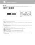
K R A ME R E LE CT R O N IC S L TD . USER MANUAL MODEL: VM-400HDCP 1:4 DVI Distributor P/N: 2900-300054 Rev 2 Contents 1 Introduction 1 2 2.1 2.2 2.3 3 Getting Started Achieving the Best Performance Safety Instructions Recycling Kramer Products Overview 2 2 3 3 4 4 Defining the VM-400HDCP 1:4 DVI Distributor 5 5 Connecting the VM-400HDCP 7 6 Acquiring the EDID 7 Technical Specifications 10 8 Default EDID 11 8 Figures Figure 1: VM-400HDCP 1:4 DVI Distributor Front Panel Figure 2: VM-400HDCP 1:4 DVI Distributor Rear Panel Figure 3: Connecting the VM-400HDCP 1:4 DVI Distributor VM-400HDCP – Contents 5 6 7 i 1 Introduction Welcome to Kramer Electronics! Since 1981, Kramer Electronics has been providing a world of unique, creative, and affordable solutions to the vast range of problems that confront the video, audio, presentation, and broadcasting professional on a daily basis. In recent years, we have redesigned and upgraded most of our line, making the best even better! Our 1,000-plus different models now appear in 11 groups that are clearly defined by function: GROUP 1: Distribution Amplifiers; GROUP 2: Switchers and Matrix Switchers; GROUP 3: Control Systems; GROUP 4: Format/Standards Converters; GROUP 5: Range Extenders and Repeaters; GROUP 6: Specialty AV Products; GROUP 7: Scan Converters and Scalers; GROUP 8: Cables and Connectors; GROUP 9: Room Connectivity; GROUP 10: Accessories and Rack Adapters and GROUP 11: Sierra Products. Congratulations on purchasing your Kramer MegaTOOLS® VM-400HDCP 1:4 DVI Distributor, which is ideal for the following typical applications: Home theater, presentation and multimedia applications Rental and staging VM-400HDCP - Introduction 1 2 Getting Started We recommend that you: Unpack the equipment carefully and save the original box and packaging materials for possible future shipment Review the contents of this user manual i 2.1 Go to http://www.kramerelectronics.com/support/product_downloads.asp to check for up-to-date user manuals, application programs, and to check if firmware upgrades are available (where appropriate). Achieving the Best Performance To achieve the best performance: Use only good quality connection cables (we recommend Kramer highperformance, high-resolution cables) to avoid interference, deterioration in signal quality due to poor matching, and elevated noise levels (often associated with low quality cables) Do not secure the cables in tight bundles or roll the slack into tight coils Avoid interference from neighboring electrical appliances that may adversely influence signal quality Position your Kramer VM-400HDCP away from moisture, excessive sunlight and dust ! 2 This equipment is to be used only inside a building. It may only be connected to other equipment that is installed inside a building. VM-400HDCP - Getting Started 2.2 Safety Instructions ! 2.3 Caution: There are no operator serviceable parts inside the unit Warning: Use only the Kramer Electronics input power wall adapter that is provided with the unit Warning: Disconnect the power and unplug the unit from the wall before installing Recycling Kramer Products The Waste Electrical and Electronic Equipment (WEEE) Directive 2002/96/EC aims to reduce the amount of WEEE sent for disposal to landfill or incineration by requiring it to be collected and recycled. To comply with the WEEE Directive, Kramer Electronics has made arrangements with the European Advanced Recycling Network (EARN) and will cover any costs of treatment, recycling and recovery of waste Kramer Electronics branded equipment on arrival at the EARN facility. For details of Kramer’s recycling arrangements in your particular country go to our recycling pages at http://www.kramerelectronics.com/support/recycling/. VM-400HDCP - Getting Started 3 3 Overview The high quality VM-400HDCP accepts an HDMI signal and distributes the selected signal to up to four outputs over DVI connectors. The VM-400HDCP features: Maximum data rate of 4.95Gbps (1.65Gbps per graphic channel) I-EDIDPro™ Kramer Intelligent EDID Processing™, an intelligent EDID handling & processing algorithm that ensures Plug and Play operation for DVI/HDMI systems Support for HDCP signals Equalization and reclocking of the data The ability to use a default EDID or acquire the EDID from one output or from all connected outputs (auto-mix) A MegaTOOLS® sized enclosure where the device can be mounted in a rack using the optional RK-T2B adapter 4 VM-400HDCP - Overview 4 Defining the VM-400HDCP 1:4 DVI Distributor Figure 1 defines the front panel of the VM-400HDCP. Figure 1: VM-400HDCP 1:4 DVI Distributor Front Panel # Feature Function 1 INPUT DVI Connector Connect to a DVI source 2 MONITOR OUT DVI Loop Connector Connect to a DVI acceptor for input monitoring 3 READ Button Lights when configuring the EDID EDID 4 Press to acquire the EDID following selecting the EDID source. Press again to indicate the EDID status (see Section 6) SELECT Button Press to select the EDID source (single output, Auto-Mix or default), see Section 6 Lights when configuring the EDID 5 MONITOR LED Lights green when an output is connected to the Monitor Out connector and is active. The LED flashes to indicate the source of the EDID acquired (see Section 6) or when connecting a non HDCP display while providing HDCP content to the VM-400HDCP 6 OUT1, OUT 2, OUT 3 LEDs Lights green when an output is connected and is active. The LED flashes to indicate the source of the EDID acquired (see Section 6) or when connecting a non HDCP display while providing HDCP content to the VM-400HDCP 7 ON LED Lights green when the device receives power VM-400HDCP - Defining the VM-400HDCP 1:4 DVI Distributor 5 Figure 2 defines the rear panel of the VM-400HDCP. Figure 2: VM-400HDCP 1:4 DVI Distributor Rear Panel 6 # Feature Function 8 OUT 1 DVI Connector Connect to a DVI acceptor 9 OUT 2 DVI Connector Connect to a DVI acceptor 10 OUT 3 DVI Connector Connect to a DVI acceptor 11 5V DC Connector Connect to the power adapter, center pin positive VM-400HDCP - Defining the VM-400HDCP 1:4 DVI Distributor 5 Connecting the VM-400HDCP i Always switch off the power to any device before connecting it to your VM-400HDCP. After connecting your VM-400HDCP, connect its power and then switch on the power to the other devices. Figure 3: Connecting the VM-400HDCP 1:4 DVI Distributor To connect the VM-400HDCP as illustrated in the example in Figure 3: 1. Connect the DVI source (for example, a DVD player) to the DVI Input connector on the front panel. 2. Connect the DVI outputs and loop monitor to up to four DVI acceptors (for example, an LCD TV and a plasma display). 3. Connect the power adapter to the VM-400HDCP and to the mains electricity (not shown in Figure 3). VM-400HDCP - Connecting the VM-400HDCP 7 6 Acquiring the EDID Each input on the VM-400HDCP has a factory default EDID loaded (see Section 8). This lets you connect the power before having to connect one of the acceptors. The factory-default is the EDID which is programmed into the VM-400HDCP before being shipped. The EDID can be acquired from: This is usually done only once when the machine is being set up in an installation. Once acquired, the EDID is saved in non-volatile memory and further acquisition is not necessary. One output The default EDID Up to four connected outputs using the Auto-mix Mode The EDID acquired is taken from the common resolutions of all the connected outputs. For example, if several displays with different resolutions are connected to the outputs, the acquired EDID supports the common resolutions, as well as other parameters included in the EDID. Repeatedly pressing the EDID SELECT button cycles through the EDID sources in the following order: If you attempt to acquire the EDID from an output that is not connected the default EDID is acquired. Monitor (Monitor LED flashes) Output 1 (Output 1 LED flashes) Output 2 (Output 2 LED flashes) Output 3 (Output 3 LED flashes) Default EDID (all LEDs flash) Auto-Mix EDID (all LEDs light) To store the selected EDID, press EDID READ as described in the following examples. To cancel the EDID modification wait for a few seconds without touching any button. 8 VM-400HDCP - Acquiring the EDID To acquire the EDID from Output 3: 1. Press the EDID SELECT button repeatedly until OUTPUT 3 LED flashes. 2. Press and hold the EDID READ button until the LED stops flashing. The EDID from Output 3 is now stored at the input. To acquire the EDID from auto-mix: 1. Press the EDID SELECT button repeatedly until all OUTPUT LEDs light. 2. Press and hold the EDID READ button until the LEDs turn off. The auto-mix EDID is now stored at the input. To check which EDID is stored: Briefly press the EDID SELECT button once. The relevant LEDs indicate which EDID is stored at the input as follows: The MONITOR LED flashes—the EDID from MONITOR was the last acquired OUTPUT 1 LED flashes—the EDID from OUTPUT 1 was the last acquired OUTPUT 2 LED flashes—the EDID from OUTPUT 2 was the last acquired, and so on All OUTPUT LEDs flash—the default EDID was the last acquired All OUTPUT LEDs light—the Auto-Mix EDID was the last acquired The EDID acquired is taken from the common resolutions of all the connected outputs. For example, if several displays with different resolutions are connected to the outputs, the acquired EDID supports the common resolutions, as well as other parameters included in the EDID. VM-400HDCP - Acquiring the EDID 9 7 Technical Specifications INPUT: 1 DVI connector OUTPUTS: 4 DVI connectors BANDWIDTH: 4.95Gbps (1.65Gbps per graphic channel) STANDARD COMPLIANCE: Supports HDCP INDICATOR LEDs: POWER, OUTPUT POWER CONSUMPTION: 5V DC, 1.2A OPERATING TEMPERATURE: 0° to +40°C (32° to 104°F) STORAGE TEMPERATURE: -40° to +70°C (-40° to 158°F) HUMIDITY: 10% to 90%, RHL non-condensing DIMENSIONS: 18.8cm x 11.27cm x 2.57cm (7.4" x 4.44" x 1.01”) W, D, H WEIGHT: 0.42kg (0.93lbs) approx. ACCESSORIES: Power supply OPTIONS: RK-T2B 19” rack adapter Specifications are subject to change without notice at http://www.kramerelectronics.com 10 VM-400HDCP - Technical Specifications 8 Default EDID Monitor Model name............... VM400HDCP Manufacturer............. KRM Plug and Play ID......... KRM0400 Serial number............ 505-707455010 Manufacture date......... 2009, ISO week 10 Filter driver............ None ------------------------EDID revision............ 1.3 Input signal type........ Digital Color bit depth.......... Undefined Display type............. RGB color Screen size.............. 520 x 320 mm (24.0 in) Power management......... Standby, Suspend, Active off/sleep Extension blocs.......... 1 (CEA-EXT) ------------------------DDC/CI................... n/a Color characteristics Default color space...... Non-sRGB Display gamma............ 2.20 Red chromaticity......... Rx 0.674 - Ry 0.319 Green chromaticity....... Gx 0.188 - Gy 0.706 Blue chromaticity........ Bx 0.148 - By 0.064 White point (default).... Wx 0.313 - Wy 0.329 Additional descriptors... None Timing characteristics Horizontal scan range.... 30-83kHz Vertical scan range...... 56-76Hz Video bandwidth.......... 170MHz CVT standard............. Not supported GTF standard............. Not supported Additional descriptors... None Preferred timing......... Yes Native/preferred timing.. 1280x720p at 60Hz (16:10) Modeline............... "1280x720" 74.250 1280 1390 1430 1650 720 725 730 750 +hsync +vsync Standard timings supported 720 x 400p at 70Hz - IBM VGA 640 x 480p at 60Hz - IBM VGA 640 x 480p at 75Hz - VESA 800 x 600p at 60Hz - VESA 800 x 600p at 75Hz - VESA 1024 x 768p at 60Hz - VESA 1024 x 768p at 75Hz - VESA 1280 x 1024p at 75Hz - VESA 1280 x 1024p at 60Hz - VESA STD 1600 x 1200p at 60Hz - VESA STD 1152 x 864p at 75Hz - VESA STD EIA/CEA-861 Information Revision number.......... 3 IT underscan............. Supported Basic audio.............. Supported YCbCr 4:4:4.............. Supported YCbCr 4:2:2.............. Supported Native formats........... 1 Detailed timing #1....... 1920x1080p at 60Hz (16:10) Modeline............... "1920x1080" 148.500 1920 2008 2052 2200 1080 1084 1089 1125 +hsync +vsync Detailed timing #2....... 1920x1080i at 60Hz (16:10) Modeline............... "1920x1080" 74.250 1920 2008 2052 2200 1080 1084 1094 1124 interlace +hsync +vsync Detailed timing #3....... 1280x720p at 60Hz (16:10) Modeline............... "1280x720" 74.250 1280 1390 1430 1650 720 725 730 750 +hsync +vsync Detailed timing #4....... 720x480p at 60Hz (16:10) Modeline............... "720x480" 27.000 720 736 798 858 480 489 495 525 -hsync -vsync VM-400HDCP - Default EDID 11 CE video identifiers (VICs) - timing/formats supported 1920 x 1080p at 60Hz - HDTV (16:9, 1:1) 1920 x 1080i at 60Hz - HDTV (16:9, 1:1) 1280 x 720p at 60Hz - HDTV (16:9, 1:1) [Native] 720 x 480p at 60Hz - EDTV (16:9, 32:27) 720 x 480p at 60Hz - EDTV (4:3, 8:9) 720 x 480i at 60Hz - Doublescan (16:9, 32:27) 720 x 576i at 50Hz - Doublescan (16:9, 64:45) 640 x 480p at 60Hz - Default (4:3, 1:1) NB: NTSC refresh rate = (Hz*1000)/1001 CE audio data (formats supported) LPCM 2-channel, 16/20/24 bit depths at 32/44/48 kHz CE vendor specific data (VSDB) IEEE registration number. 0x000C03 CEC physical address..... 1.0.0.0 Maximum TMDS clock....... 165MHz CE speaker allocation data Channel configuration.... 2.0 Front left/right......... Yes Front LFE................ No Front center............. No Rear left/right.......... No Rear center.............. No Front left/right center.. No Rear left/right center... No Rear LFE................. No Report information Date generated........... 19-Jan-12 Software revision........ 2.60.0.972 Data source.............. File Operating system......... 5.1.2600.2.Service Pack 3 Raw data 00,FF,FF,FF,FF,FF,FF,00,2E,4D,00,04,01,01,01,01,0A,13,01,03,80,34,20,78,EA,B3,25,AC,51,30,B4,26, 10,50,54,A5,4B,00,81,80,A9,40,71,4F,01,01,01,01,01,01,01,01,01,01,01,1D,00,72,51,D0,1E,20,6E,28, 55,00,07,44,21,00,00,1E,00,00,00,FF,00,35,30,35,2D,37,30,37,34,35,35,30,31,30,00,00,00,FC,00,56, 4D,34,30,30,48,44,43,50,20,20,20,0A,00,00,00,FD,00,38,4C,1E,53,11,00,0A,20,20,20,20,20,20,01,74, 02,03,1B,F1,48,10,05,84,03,02,07,16,01,23,09,07,07,65,03,0C,00,10,00,83,01,00,00,02,3A,80,18,71, 38,2D,40,58,2C,45,00,07,44,21,00,00,1E,01,1D,80,18,71,1C,16,20,58,2C,25,00,07,44,21,00,00,9E,01, 1D,00,72,51,D0,1E,20,6E,28,55,00,07,44,21,00,00,1E,8C,0A,D0,8A,20,E0,2D,10,10,3E,96,00,07,44,21, 00,00,18,00,00,00,00,00,00,00,00,00,00,00,00,00,00,00,00,00,00,00,00,00,00,00,00,00,00,00,00,47 12 VM-400HDCP - Default EDID For the latest information on our products and a list of Kramer distributors, visit our Web site where updates to this user manual may be found. We welcome your questions, comments, and feedback. Web site: www.kramerelectronics.com E-mail: [email protected] ! P/N: SAFETY WARNING Disconnect the unit from the power supply before opening and servicing 2900- 300054 Rev: 2