1
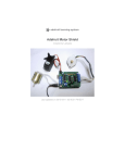
Adafruit Motor Shield
Created by lady ada
Last updated on 2015-06-07 05:20:10 PM EDT
Guide Contents
Guide Contents
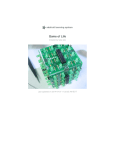
Overview
FAQ
Make It!
2
4
6
10
Lets go!
10
Preparation
11
Tutorials
Tools
11
11
Parts List
Solder It
Use It!
Library Install
16
19
36
37
First Install the Arduino Library
Power Usage
Powering your DC motors, voltage and current requirements
How to set up the Arduino + Shield for powering motors
Using RC Servos
Using Stepper Motors
Using DC Motors
DC motors are used for all sort of robotic projects.
AF_DCMotor Class
AF_DCMotor motorname(portnum, freq)
setSpeed(speed)
run(cmd)
AF_Stepper Class
AF_Stepper steppername(steps, portnumber)
step(steps, direction, style)
setSpeed(RPMspeed)
onestep(direction, stepstyle)
release()
Resources
Motor ideas and tutorials
© Adafruit Industries
https://learn.adafruit.com/adafruit-motor-shield
37
38
38
38
41
43
46
46
48
48
50
50
52
52
53
54
54
55
56
56
Page 2 of 58
Downloads
57
Schematics & Layout
Firmware
57
57
Forums
© Adafruit Industries
58
https://learn.adafruit.com/adafruit-motor-shield
Page 3 of 58
Overview
This tutorial is for the now ancient V1 Motor shield. Chances are you have a V2, check out the
tutorial https://learn.adafruit.com/adafruit-motor-shield-v2-for-arduino This tutorial is for
historical reference and previous customers only!
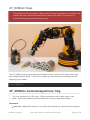
Arduino is a great starting point for electronics, and with a motor shield it can also be a nice tidy
platform for robotics and mechatronics. Here is a design for a full-featured motor shield that will be
able to power many simple to medium-complexity projects.
2 connections for 5V 'hobby' servos connected to the Arduino's high-resolution dedicated
timer - no jitter!
Up to 4 bi-directional DC motors with individual 8-bit speed selection (so, about 0.5%
resolution)
Up to 2 stepper motors (unipolar or bipolar) with single coil, double coil, interleaved or
micro-stepping.
4 H-Bridges: L293D chipset provides 0.6A per bridge (1.2A peak) with thermal shutdown
© Adafruit Industries
https://learn.adafruit.com/adafruit-motor-shield
Page 4 of 58
protection, 4.5V to 25V
Pull down resistors keep motors disabled during power-up
Big terminal block connectors to easily hook up wires (10-22AWG) and power
Arduino reset button brought up top
2-pin terminal block to connect external power, for seperate logic/motor supplies
Tested compatible with Mega, Diecimila, & Duemilanove
Full kit available for purchase from the Adafruit shop. (http://adafru.it/81)
Download the easy-to-use Arduino software libraries and you're ready to
go! (http://adafru.it/aON)
© Adafruit Industries
https://learn.adafruit.com/adafruit-motor-shield
Page 5 of 58
FAQ
This tutorial is for the now ancient V1 Motor shield. Chances are you have a V2, check out the
tutorial https://learn.adafruit.com/adafruit-motor-shield-v2-for-arduino This tutorial is for
historical reference and previous customers only!
How many motors can I use with this shield?
You can use 2 DC servos that run on 5V and up to 4 DC motors or 2 stepper motors (or 1
stepper and up to 2 DC motors)
Can I connect more motors?
No, at this time it is not possible to stack the shield or otherwise connect it up easily to control 4
steppers, for example.
HELP! My motor doesnt work! - HELP! My motor doesnt work!...But the servos work FINE!
Is the LED lit? The Stepper and DC motor connections wont do a single thing if the LED is not lit
Don't bother writing up uploading code or wiring up motors if the LED doesn't light up, its not
going to work.
What is the LED for?
The LED indicates the DC/Stepper motor power supply is working. If it is not lit, then the
DC/Stepper motors will not run. The servo ports are 5V powered and does not use the DC motor
supply.
I'm trying to build this robot and it doesn't seem to run on a 9V battery....
Please read the user manual (http://adafru.it/aOz) for information about appropriate power
supplies.
Can this shield control small 3V motors?
Not really, its meant for larger, 6V+ motors. It does not work for 3V motors unless you overdrive
them at 6V and then they will burn out faster
What is the power connector on the shield for? How do I power my motors?
Please read the user manual (http://adafru.it/aOz) for information about appropriate power
supplies.
My Arduino freaks out when the motors are running! Is the shield broken?
Motors take a lot of power, and can cause 'brownouts' that reset the Arduino. For that reason the
shield is designed for seperate (split) supplies - one for the electronics and one for the motor.
Doing this will prevent brownouts. Please read the user manual (http://adafru.it/aOz) for
information about appropriate power supplies.
© Adafruit Industries
https://learn.adafruit.com/adafruit-motor-shield
Page 6 of 58
I have good solid power supplies, but the DC motors seem to 'cut out' or 'skip'.
Try soldering a ceramic or disc 0.1uF capacitor between the motor tabs (on the motor itself!) this
will reduce noise that could be feeding back into the circuit (thanks macegr (http://adafru.it/clc)!)
What if I need more than 600mA per motor?
You can subsitute SN754410's (at your risk) or piggyback solder some more L293D drivers on
top of the existing ones. (http://adafru.it/aOz)
What pins are not used on the motor shield?
All 6 analog input pins are available. They can also be used as digital pins (pins #14 thru
19)
Digital pin 2, and 13 are not used.
The following pins are in use only if the DC/Stepper noted is in use:
Digital pin 11: DC Motor #1 / Stepper #1 (activation/speed control)
Digital pin 3: DC Motor #2 / Stepper #1 (activation/speed control)
Digital pin 5: DC Motor #3 / Stepper #2 (activation/speed control)
Digital pin 6: DC Motor #4 / Stepper #2 (activation/speed control)
The following pins are in use if any DC/steppers are used
Digital pin 4, 7, 8 and 12 are used to drive the DC/Stepper motors via the 74HC595 serial-toparallel latch
The following pins are used only if that particular servo is in use:
Digitals pin 9: Servo #1 control
Digital pin 10: Servo #2 control
Which pins are connected to the DC/Stepper motors?
The DC/Stepper motors are NOT connected to the Arduino directly. They are connected to the
74HC595 latch which is spoken to by the Arduino. You CANNOT talk directly to the motors, you
MUST use the motor shield library.
Huh? I don't understand...
You can try reading this nice overview written by Michael K (http://adafru.it/aO9)
How can I connect to the unused pins?
The analog pins (analog 0-5 also known as digital pins 14-19) are broken out in the bottom right
corner.
Pin 2 has a small breakout since its the only truly unused pin
The remaining pins are not broken out because they could be used by the motor shield. If you
are sure that you are not using those pins then you can connect to them by using stacking
© Adafruit Industries
https://learn.adafruit.com/adafruit-motor-shield
Page 7 of 58
headers when assembling the kit or soldering onto the top of the header with wires, or using a
"Wing shield"
I get the following error trying to run the example code: "error: AFMotor.h: No such file or
directory...."
Make sure you have installed the AFMotor library
How do I install the library?
Read our tutorial on libraries (http://adafru.it/aYG)
I have two stepper motors and I want to run them simulaneously but the example code can only
control one and then the other?
The stepper motor library step() routine does not have the ability to run both motors at a time.
Instead, you will have to 'interleave' the calls. For example, to have both motors step forward
100 times you must write code like this:
for (i=0; i<100; i++) {
motor1.step(1, FORWARD, SINGLE);
motor2.step(1, FORWARD, SINGLE);
}
If you want more intelligent control, check out the AccelStepper library (in the Downloads section)
which has some concurrent stepper motor control examples
What are some 'suggested motors'?
Most people buy motors from surplus shops and no motor will make everyone happy
However, since its a popular question, I suggest buying motors from Pololu (DC
Servos (http://adafru.it/aOa), DC motors (http://adafru.it/aOb)) or Jameco (all
sorts (http://adafru.it/aOc)!) As well as the many surplus webshops (http://adafru.it/aOd).
Is the motor shield compatible with the UNO R3 or Mega R3? What about the extra pins?
The motor shield is compatible with the R3 UNO and MEGA. The R3s have 2 extra pins on each
header. These are duplicates of other pins on the header and are not needed by the shield.
I'm using a 4WD robot platform and I can't get anything to work.
The motors used in the 4WD robot platforms from Maker Shed, DF Robotics, Jameco and others
have a lot of "brush noise". This feeds back into the Arduino circuitry and causes unstable
operation. This problem can be solved by soldering 3 noise suppression capacitors to the motor.
1 between the motor terminals, and one from each terminal to the motor casing.
© Adafruit Industries
https://learn.adafruit.com/adafruit-motor-shield
Page 8 of 58
But my motor already has a capacitor on it and it still doesn't work.
These motors generate a lot of brush noise and usually need the full 3-capacitor treatment for
adequate suppression.
Why don't you just design capacitors into the shield?
They would not be effective there. The noise must be suppressed at the source or the motor
leads will act like antennae and broadcast it to the rest of the system.
© Adafruit Industries
https://learn.adafruit.com/adafruit-motor-shield
Page 9 of 58
Make It!
This tutorial is for the now ancient V1 Motor shield. Chances are you have a V2, check out the
tutorial https://learn.adafruit.com/adafruit-motor-shield-v2-for-arduino This tutorial is for
historical reference and previous customers only!
Lets go!
This is a vey easy kit to make, just go through each of these steps to build the kit
1. Tools and preparation (http://adafru.it/aOv)
2. Check the parts list (http://adafru.it/aOw)
3. Solder it (http://adafru.it/aOx)
© Adafruit Industries
https://learn.adafruit.com/adafruit-motor-shield
Page 10 of 58
Preparation
This tutorial is for the now ancient V1 Motor shield. Chances are you have a V2, check out the
tutorial https://learn.adafruit.com/adafruit-motor-shield-v2-for-arduino This tutorial is for
historical reference and previous customers only!
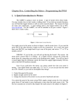
Tutorials
Learn how to solder with tons of tutorials! (http://adafru.it/aOm)
(http://adafru.it/aOm)
Don't forget to learn how to use your multimeter too! (http://adafru.it/aOy)
Tools
There are a few tools that are required for assembly. None of these tools are included. If you don't
have them, now would be a good time to borrow or purchase them. They are very very handy
whenever assembling/fixing/modifying electronic devices! I provide links to buy them, but of course,
you should get them where ever is most convenient/inexpensive. Many of these parts are available
in a place like Radio Shack or other (higher quality) DIY electronics stores.
Soldering iron
Any entry level 'all-in-one' soldering iron that you
might find at your local hardware store should
work. As with most things in life, you get what you
pay for.
Upgrading to a higher end soldering iron setup, like
the Hakko FX-888 that we stock in our
store (http://adafru.it/180), will make soldering fun
and easy.
Do not use a "ColdHeat" soldering iron! They are
not suitable for delicate electronics work and can
damage the kit (see here (http://adafru.it/aOo)).
Click here to buy our entry level adjustable 30W
110V soldering iron. (http://adafru.it/180)
Click here to upgrade to a Genuine Hakko FX-888
adjustable temperature soldering
iron. (http://adafru.it/303)
© Adafruit Industries
https://learn.adafruit.com/adafruit-motor-shield
Page 11 of 58
Solder
You will want rosin core, 60/40 solder. Good solder
is a good thing. Bad solder leads to bridging and
cold solder joints which can be tough to find.
Click here to buy a spool of leaded solder
(recommended for beginners). (http://adafru.it/145)
Click here to buy a spool of lead-free
solder. (http://adafru.it/734)
© Adafruit Industries
https://learn.adafruit.com/adafruit-motor-shield
Page 12 of 58
Multimeter
You will need a good quality basic multimeter that
can measure voltage and continuity.
Click here to buy a basic
multimeter. (http://adafru.it/71)
Click here to buy a top of the line
multimeter. (http://adafru.it/308)
Click here to buy a pocket
multimeter. (http://adafru.it/850)
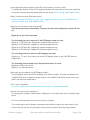
Flush Diagonal Cutters
© Adafruit Industries
https://learn.adafruit.com/adafruit-motor-shield
Page 13 of 58
You will need flush diagonal cutters to trim the
wires and leads off of components once you have
soldered them in place.
Click here to buy our favorite
cutters. (http://adafru.it/152)
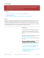
Solder Sucker
Strangely enough, that's the technical term for this
desoldering vacuum tool. Useful in cleaning up
mistakes, every electrical engineer has one of
these on their desk.
Click here to buy a one. (http://adafru.it/148)
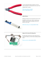
Helping Third Hand With Magnifier
Not absolutely necessary but will make things go
much much faster, and it will make soldering much
easier.
Pick one up here. (http://adafru.it/291)
© Adafruit Industries
https://learn.adafruit.com/adafruit-motor-shield
Page 14 of 58
Parts List
This tutorial is for the now ancient V1 Motor shield. Chances are you have a V2, check out the
tutorial https://learn.adafruit.com/adafruit-motor-shield-v2-for-arduino This tutorial is for
historical reference and previous customers only!
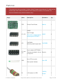
Image
Name
Description
Distributor
Qty
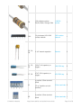
PCB
Printed Circuit Board
Adafruit
1
L293D
2
74HC595N
1
L293D
Dual H-bridge
IC1, IC2
IC3
*See note on usage page for
replacing with SN754410
74HC595N
Serial to parallel output latch
16 pin sockets (OPTIONAL!)
IC1' and
IC2'
These are included in kits as Generic
of July 2010
2
3mm LED, any color
LED1
R1
© Adafruit Industries
Motor power indicator
1.5K resistor for LED1
https://learn.adafruit.com/adafruit-motor-shield
3mm LED
1
1/4W 5%
resistor
1
Page 15 of 58
R2
10K pulldown resistor
Brown, Black, Orange, Gold
1/4W 5%
resistor
1
RN1
10-pin bussed 10K-100K
resistor network
100K resistor
network
1
C2, C4,
C6
0.1uF ceramic capacitor
Generic
3
C1, C3,
C5
100uF / 6V capacitor (or
bigger)
100uF/6V cap
3
C7, C8
47uF / 25V capacitor (or
bigger)
47uF/25V cap
2
5-position 3.5mm terminal
block
X1
X2
© Adafruit Industries
(Or a 3-position and a 2position)
2-position 3.5mm terminal
block
https://learn.adafruit.com/adafruit-motor-shield
3.5mm terminals 2
3.5mm terminals 1
Page 16 of 58
block
© Adafruit Industries
RESET
6mm tactile switch
6mm tact switch
1
PWR
Jumper/shunt
0.1" jumper
1
36 pin male header (1x36)
Generic
1
https://learn.adafruit.com/adafruit-motor-shield
Page 17 of 58
Solder It
This tutorial is for the now ancient V1 Motor shield. Chances are you have a V2, check out the
tutorial https://learn.adafruit.com/adafruit-motor-shield-v2-for-arduino This tutorial is for
historical reference and previous customers only!
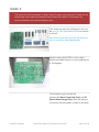
First, check that you have all the parts! Look over
the parts list here (http://adafru.it/aOw) and shown
on the left.
Also check to make sure you have the necessary
tools for assembly. (http://adafru.it/aOv)
Place the motor shield PCB in a vise or other
circuit-board holder and turn on your soldering iron
to 700 degrees.
The first parts to go in are the two
resistors, R1 (Brown Green Red Gold) and R2
(Brown Black Orange Gold). Bend the resistors
so that they look like staples, as seen in this photo.
© Adafruit Industries
https://learn.adafruit.com/adafruit-motor-shield
Page 18 of 58
Next, slip the resistors into the PCB as shown, so
that they sit flat against the circuit board. Bend the
wire legs out a bit so that when the board is flipped
over
Resistors are not polarized, that means you can
put them in "either way" and they'll work just fine.
Using your soldering iron tip, heat the resistor wire
lead and the metal ring (pad) at the same time,
after a few seconds, poke a little solder in so that it
melts into a nice cone. Remove the solder and then
remove the soldering iron. Do this for all 4 wires.
Check your work, you should have clean solder
joints.
© Adafruit Industries
https://learn.adafruit.com/adafruit-motor-shield
Page 19 of 58
Clip the long leads, just above the solder joint using
diagonal cutters.
© Adafruit Industries
https://learn.adafruit.com/adafruit-motor-shield
Page 20 of 58
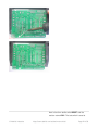
Next place the three yellow ceramic
capacitors C4, C2 andC6. Ceramic capacitors are
not polarized so you can put them in "either way"
and they work fine.
Bend the leads out just like you did with the
resistors.
Solder all 6 wires, then clip them as you did with
the resistors.
© Adafruit Industries
https://learn.adafruit.com/adafruit-motor-shield
Page 21 of 58
Next is the 6mm tactile switchRESET and the
resistor networkRN1. The tact switch is used to
© Adafruit Industries
https://learn.adafruit.com/adafruit-motor-shield
Page 22 of 58
reset the Arduino since its not possible to reach the
reset button once the motor shield is on.
The resistor network is used topull-down the pins
on the motor driver chips so that they don't power
up the motors before the Arduino sketch tells them
to.
The tactile switch can go in 'either way'. The
resistor network, however, must go in a certain
way. Make sure the end with a dot is posititioned so
it is at the same end as the X in the silkscreened
image of the resistor network. (See picture on left).
Flip the board over and solder in the resistor
network and switch. You won't need to clip the
leads as they are quite short aleady.
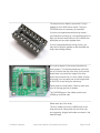
Next are the three integrated circuits (ICs) IC1,
IC2 and IC3. When ICs come from the factory, the
legs are angled out somewhat which makes it
difficult to insert them into the PCB. Prepare them
for soldering by gently bending the legs against a
flat tabletop so that they are perfectly straight.
© Adafruit Industries
https://learn.adafruit.com/adafruit-motor-shield
Page 23 of 58
The latest kits from Adafruit come with 2 16-pin
sockets for the L293D motor drivers. They are
OPTIONAL and not necessary for operation.
If you are not experienced with driving motors (
your likelyhood of wiring up a mis-specified motor is
high) you should install these so if the L293Ds are
destroyed you can easily replace them
If you are experienced with driving motors, you
may want to skip the sockets as the decrease the
chips' heat-sinking abilities.
ICs must be placed in the correct orientation to
work properly. To help with placement, each chip
has a U notch at the top of the chip. On the circuit
board there is a printed out image of the chip
outline and one end has a U notch. Make sure the
chip notch is on the same end as the image notch.
In this PCB, all are facing the same way.
Gently insert the three chips. Check to make sure
none of the legs got bent or broken.
The 74HC595 goes in the middle, and the two
L293Ds go on either side.
Solder each pin of the chips.
The four 'middle' pins of the L293D motor driver
chips are tied to a large heat sink and thus may
end up getting 'bridged' with solder as shown in the
second image.
© Adafruit Industries
https://learn.adafruit.com/adafruit-motor-shield
Page 24 of 58
Next are the three 100uF electrolytic
© Adafruit Industries
https://learn.adafruit.com/adafruit-motor-shield
Page 25 of 58
capacitors C1, C3and C5. Electrolytic capacitors
are polarized and must be placed in the correct
orientation or they could pop! The long leg of the
capacitor is the positive (+) leg and goes into the
hole marked with a +. The close-up images shown
here indicate with hole is the + one.
Capacitors are not color-coded. The body color can
vary from blue to violet to green to black sobe sure
to read the value on the side, don't depend on
the color!
© Adafruit Industries
https://learn.adafruit.com/adafruit-motor-shield
Page 26 of 58
After double-checking their polarity, solder and clip
the three capacitors.
Place the two 47uF remaining electrolytic
capacitors, C7 andC8
These are also polarized so make sure the long
lead is inserted into the + hole in the silkscreened
image.
© Adafruit Industries
https://learn.adafruit.com/adafruit-motor-shield
Page 27 of 58
Capacitors are not color-coded. The body color can
vary from blue to violet to green to black sobe sure
to read the value on the side, don't depend on
the color!
Solder and clip the two capacitors.
© Adafruit Industries
https://learn.adafruit.com/adafruit-motor-shield
Page 28 of 58
Next is the 3mm LED used to indicate motor power.
LEDs are polarized, just like capacitors, and the
long lead is the positive (+) lead.
Make sure the LED is placed correctly otherwise it
wont work!
Solder and clip the LED leads.
© Adafruit Industries
https://learn.adafruit.com/adafruit-motor-shield
Page 29 of 58
Next its time to make the headers for the jumper,
servos and arduino.
We use one stick of 36-pin 'breakaway' header,
and break it apart to make smaller strips. You can
use diagonal cutters or pliers to snap off the
pieces.
Break the 36-pin header into 2 8-pin, 2 6-pin, 2 3pin and 1 2-pin headers.
If you have an NG arduino, you may want 1 6-pin
header and 1 4-pin header instead of 2 6-pin
headers.
© Adafruit Industries
https://learn.adafruit.com/adafruit-motor-shield
Page 30 of 58
© Adafruit Industries
https://learn.adafruit.com/adafruit-motor-shield
Page 31 of 58
The 2 3-pin pieces go in the servo connections in
the top left corner. The 2-pin piece goes in the
PWR jumper in the bottom center.
Also, place the 3 large screw terminals for the
motor and external motor-power wires. If you
received only 2 and 3-position terminal blocks, slide
them together so that you have 2 5-position
terminals and 1 2-position terminal.
Solder in the 3 pieces of header and the three
terminal blocks.
© Adafruit Industries
https://learn.adafruit.com/adafruit-motor-shield
Page 32 of 58
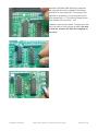
Next, place the 8-pin and 6-pin headers into the
Arduino board. This will make sure that the
headers are perfectly lined up. Make sure the
Arduino is not plugged in or powered!
Place the motor shield on top of the Arduino,
making sure that all the header lines up.
© Adafruit Industries
https://learn.adafruit.com/adafruit-motor-shield
Page 33 of 58
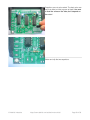
Solder in each pin of the header.
You're done!
Now go read the user manual. (http://adafru.it/aOz)
© Adafruit Industries
https://learn.adafruit.com/adafruit-motor-shield
Page 34 of 58
© Adafruit Industries
https://learn.adafruit.com/adafruit-motor-shield
Page 35 of 58
Use It!
This tutorial is for the now ancient V1 Motor shield. Chances are you have a V2, check out the
tutorial https://learn.adafruit.com/adafruit-motor-shield-v2-for-arduino This tutorial is for
historical reference and previous customers only!
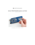
The Adafruit Motor Shield kit is a great motor controller for Arduino, but it does a little care to make
sure it's used correctly. Please read through all the User manual sections at left, especially the
section about library installation and power requirements!
© Adafruit Industries
https://learn.adafruit.com/adafruit-motor-shield
Page 36 of 58
Library Install
This tutorial is for the now ancient V1 Motor shield. Chances are you have a V2, check out the
tutorial https://learn.adafruit.com/adafruit-motor-shield-v2-for-arduino This tutorial is for
historical reference and previous customers only!
First Install the Arduino Library
Before you can use the Motor shield, you must install the AF_Motor Arduino library - this will
instruct the Arduino how to talk to the Adafruit Motor shield, and it isn't optional!
1. First, grab the library from github (http://adafru.it/aOA)
2. Uncompress the ZIP file onto your desktop
3. Rename the uncompressed folder AFMotor
4. Check that inside AFMotor is AFMotor.cpp and AFMotor.h files. If not, check the steps
above
5. Place the AFMotor folder into your arduinosketchfolder/libraries folder. For Windows, this will
probably be something like MY Documents/Arduino/libraries for Mac it will be something
likeDocuments/arduino/libraries. If this is the first time you are installing a library, you'll
need to create the libraries folder. Make sure to call it libraries exactly, no caps, no other
name.
6. Check that inside the libraries folder there is the AFMotor folder, and inside AFMotor
isAFMotor.cpp AFMotor.h and some other files
7. Quit and restart the IDE. You should now have a submenu called File->Examples>AFMotor->MotorParty
© Adafruit Industries
https://learn.adafruit.com/adafruit-motor-shield
Page 37 of 58
Power Usage
This tutorial is for the now ancient V1 Motor shield. Chances are you have a V2, check out the
tutorial https://learn.adafruit.com/adafruit-motor-shield-v2-for-arduino This tutorial is for
historical reference and previous customers only!
Powering your DC motors, voltage and current
requirements
Motors need a lot of energy, especially cheap motors since they're less efficient. The first important
thing to figure out what voltage the motor is going to use. If you're lucky your motor came with some
sort of specifications. Some small hobby motors are only intended to run at 1.5V, but its just as
common to have 6-12V motors. The motor controllers on this shield are designed to run from 4.5V
to 25V.
MOST 1.5-3V MOTORS WILL NOT WORK
Current requirements: The second thing to figure out is how much current your motor will need.
The motor driver chips that come with the kit are designed to provide up to 600 mA per motor, with
1.2A peak current. Note that once you head towards 1A you'll probably want to put a heatsink on
the motor driver, otherwise you will get thermal failure, possibly burning out the chip.
On using the SN754410: Some people use the SN754410 (http://adafru.it/aOB) motor driver chip
because it is pin-compatible, has output diodes and can provide 1A per motor, 2A peak. After
careful reading of the datasheet and discussion with TI tech support and power engineers it
appears that the output diodes were designed for ESD protection only and that using them as
kickback-protection is a hack and not guaranteed for performance. For that reason the kit does not
come with the SN754410 and instead uses the L293D with integrated kickback-protection diodes. If
you're willing to risk it, and need the extra currrent, feel free to buy SN754410's and replace the
provided chips.
Need more power? Buy another set of L293D drivers and solder them right on top of the ones on
the board (piggyback) (http://adafru.it/aOC). Voila, double the current capability! You can solder 2
more chips on top before it probably isnt going to get you much benefit
You can't run motors off of a 9V battery so don't even waste your time/batteries! Use a big
Lead Acid or NiMH battery pack. Its also very much suggested that you set up two power supplies
(split supply) one for the Arduino and one for the motors. 99% of 'weird motor problems' are due
to noise on the power line from sharing power supplies and/or not having a powerful enough supply!
How to set up the Arduino + Shield for powering motors
Servos are powered off of the same regulated 5V that the Arduino uses. This is OK for the
© Adafruit Industries
https://learn.adafruit.com/adafruit-motor-shield
Page 38 of 58
small hobby servos suggested. If you want something beefier, cut the trace going to + on the servo
connectors and wire up your own 5-6V supply!
The DC motors are powered off of a 'high voltage supply' and NOT the regulated 5V. Don't
connect the motor power supply to the 5V line. This is a very very very bad idea unless you are
sure you know what you're doing!
There are two places you can get your motor 'high voltage supply' from. One is the DC jack on the
Arduino board and the other is the 2-terminal block on the shield that is labeled EXT_PWR. The DC
Jack on the Arduino has a protection diode so you won't be able to mess things up too bad if you
plug in the wrong kind of power. However the EXT_PWR terminals on the shield do not have a
protection diode (for a fairly good reason). Be utterly careful not to plug it in backwards or you
will destroy the motor shield and/or your Arduino!
Here's how it works:
If you would like to have a single DC power supply for the Arduino and motors, simply plug it
into the DC jack on the Arduino or the 2-pin PWR_EXT block on the shield. Place the power jumper
on the motor shield.
If you have a Diecimila Arduino, set the Arduino power source jumper to EXT.
Note that you may have problems with Arduino resets if the battery supply is not able to provide
constant power, and it is not a suggested way of powering your motor project
If you would like to have the Arduino powered off of USB and the motors powered off of a DC
power supply, plug in the USB cable. Then connect the motor supply to the PWR_EXT block on
© Adafruit Industries
https://learn.adafruit.com/adafruit-motor-shield
Page 39 of 58
the shield. Do not place the jumper on the shield. This is a suggested method of powering your
motor project
(If you have a Diecimila Arduino, don't forget to set the Arduino power jumper to USB. If you have a
Diecimila, you can alternately do the following: plug the DC power supply into the Arduino, and place
the jumper on the motor shield.)
If you would like to have 2 seperate DC power supplies for the Arduino and motors. Plug in the
supply for the Arduino into the DC jack, and connect the motor supply to the PWR_EXT block. Make
sure the jumper is removed from the motor shield.
If you have a Diecimila Arduino, set the Arduino jumper to EXT. This is a suggested method of
powering your motor project
Either way, if you want to use the DC motor/Stepper system the motor shield LED should be
lit indicating good motor power
© Adafruit Industries
https://learn.adafruit.com/adafruit-motor-shield
Page 40 of 58
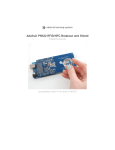
Using RC Servos
This tutorial is for the now ancient V1 Motor shield. Chances are you have a V2, check out the
tutorial https://learn.adafruit.com/adafruit-motor-shield-v2-for-arduino This tutorial is for
historical reference and previous customers only!
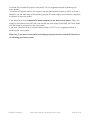
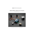
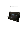
Hobby servos are the easiest way to get going with motor control. They have a 3-pin 0.1" female
header connection with +5V, ground and signal inputs. The motor shield simply brings out the 16bit
PWM output lines to two 3-pin headers so that its easy to plug in and go. They can take a lot of
power so a 9V battery wont last more than a few minutes!
The nice thing about using the onboard PWM is that its very precise and goes about its business in
the background. You can use the built in Servo library
Using the servos is easy, please read the official Arduino documentation for how to use them and
see the example Servo sketches in the IDE (http://adafru.it/aOD).
Power for the Servos comes from the Arduino's on-board 5V regulator, powered directly from
© Adafruit Industries
https://learn.adafruit.com/adafruit-motor-shield
Page 41 of 58
the USB or DC power jack on the Arduino. If you need an external supply, cut the trace right
below the servo pins (on v1.2 boards) and connect a 5V or 6V DC supply directly. Using an external
supply is for advanced users as you can accidentally destroy the servos by connecting a power
supply incorrectly!
When using the external supply header for servos, take care that the bottom of the header
pins do not contact the metal USB port housing on the Arduino. A piece of electrical tape on
the housing will protect against shorts.
© Adafruit Industries
https://learn.adafruit.com/adafruit-motor-shield
Page 42 of 58
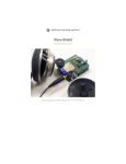
Using Stepper Motors
This tutorial is for the now ancient V1 Motor shield. Chances are you have a V2, check out the
tutorial https://learn.adafruit.com/adafruit-motor-shield-v2-for-arduino This tutorial is for
historical reference and previous customers only!
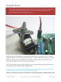
Stepper motors are great for (semi-)precise control, perfect for many robot and CNC projects. This
motor shield supports up to 2 stepper motors. The library works identically for bi-polar and uni-polar
motors
For unipolar motors: to connect up the stepper, first figure out which pins connected to which coil,
and which pins are the center taps. If its a 5-wire motor then there will be 1 that is the center tap for
both coils. Theres plenty of tutorials online on how to reverse engineer the coils
pinout. (http://adafru.it/aOO) The center taps should both be connected together to the GND
terminal on the motor shield output block. then coil 1 should connect to one motor port (say M1 or
M3) and coil 2 should connect to the other motor port (M2 or M4).
© Adafruit Industries
https://learn.adafruit.com/adafruit-motor-shield
Page 43 of 58
For bipolar motors: its just like unipolar motors except theres no 5th wire to connect to ground. The
code is exactly the same.
Running a stepper is a little more intricate than running a DC motor but its still very easy
1. Make sure you #include <AFMotor.h>
2. Create the stepper motor object with AF_Stepper(steps, stepper#) to setup the motor Hbridge and latches. Steps indicates how many steps per revolution the motor has. a
7.5degree/step motor has 360/7.5 = 48 steps. Stepper# is which port it is connected to. If
you're using M1 and M2, its port 1. If you're using M3 and M4 it's port 2
3. Set the speed of the motor using setSpeed(rpm) where rpm is how many revolutions per
minute you want the stepper to turn.
4. Then every time you want the motor to move, call the step(#steps, direction, steptype)
procedure.#steps is how many steps you'd like it to take. direction is either FORWARD or
BACKWARD and the step type is SINGLE, DOUBLE. INTERLEAVE or MICROSTEP.
"Single" means single-coil activation, "double" means 2 coils are activated at once (for higher
torque) and "interleave" means that it alternates between single and double to get twice the
resolution (but of course its half the speed). "Microstepping" is a method where the coils are
PWM'd to create smooth motion between steps. Theres tons of information about the pros
and cons of these different stepping methods in the resources page. (http://adafru.it/aOO)
You can use whichever stepping method you want, changing it "on the fly" to as you may
want minimum power, more torque, or more precision.
5. By default, the motor will 'hold' the position after its done stepping. If you want to release all
the coils, so that it can spin freely, call release()
6. The stepping commands are 'blocking' and will return once the steps have finished.
Because the stepping commands 'block' - you have to instruct the Stepper motors each time you
want them to move. If you want to have more of a 'background task' stepper control, check out
AccelStepper library (http://adafru.it/aOL) (install similarly to how you did with AFMotor) which has
some examples for controlling two steppers simultaneously with varying accelleration
© Adafruit Industries
https://learn.adafruit.com/adafruit-motor-shield
Page 44 of 58
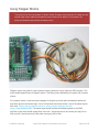
#include <AFMotor.h>
AF_Stepper motor(48, 2);
void setup() {
Serial.begin(9600);
// set up Serial library at 9600 bps
Serial.println("Stepper test!");
motor.setSpeed(10); // 10 rpm
motor.step(100, FORWARD, SINGLE);
motor.release();
delay(1000);
}
void loop() {
motor.step(100, FORWARD, SINGLE);
motor.step(100, BACKWARD, SINGLE);
motor.step(100, FORWARD, DOUBLE);
motor.step(100, BACKWARD, DOUBLE);
motor.step(100, FORWARD, INTERLEAVE);
motor.step(100, BACKWARD, INTERLEAVE);
motor.step(100, FORWARD, MICROSTEP);
motor.step(100, BACKWARD, MICROSTEP);
}
© Adafruit Industries
https://learn.adafruit.com/adafruit-motor-shield
Page 45 of 58
Using DC Motors
This tutorial is for the now ancient V1 Motor shield. Chances are you have a V2, check out the
tutorial https://learn.adafruit.com/adafruit-motor-shield-v2-for-arduino This tutorial is for
historical reference and previous customers only!
DC motors are used for all sort of robotic projects.
The motor shield can drive up to 4 DC motors bi-directionally. That means they can be driven
forwards and backwards. The speed can also be varied at 0.5% increments using the high-quality
built in PWM. This means the speed is very smooth and won't vary!
Note that the H-bridge chip is not meant for driving loads over 0.6A or that peak over 1.2A so this is
for small motors. Check the datasheet for information about the motor to verify its OK.
To connect a motor, simply solder two wires to the terminals and then connect them to either the
M1, M2, M3, or M4. Then follow these steps in your sketch
© Adafruit Industries
https://learn.adafruit.com/adafruit-motor-shield
Page 46 of 58
1. Make sure you #include <AFMotor.h>
2. Create the AF_DCMotor object with AF_DCMotor(motor#, frequency), to setup the motor
H-bridge and latches. The constructor takes two arguments.
The first is which port the motor is connected to, 1, 2, 3 or 4.
frequency is how fast the speed controlling signal is.
For motors 1 and 2 you can choose MOTOR12_64KHZ, MOTOR12_8KHZ,
MOTOR12_2KHZ, orMOTOR12_1KHZ. A high speed like 64KHz wont be audible but a low
speed like 1KHz will use less power. Motors 3 & 4 are only possible to run at 1KHz and will
ignore any setting given
3. Then you can set the speed of the motor using setSpeed(speed) where the speed ranges
from 0 (stopped) to 255 (full speed). You can set the speed whenever you want.
4. To run the motor, call run(direction) where direction is FORWARD, BACKWARD or
RELEASE. Of course, the Arduino doesn't actually know if the motor is 'forward' or
'backward', so if you want to change which way it thinks is forward, simply swap the two wires
from the motor to the shield.
#include <AFMotor.h>
AF_DCMotor motor(2, MOTOR12_64KHZ); // create motor #2, 64KHz pwm
void setup() {
Serial.begin(9600);
// set up Serial library at 9600 bps
Serial.println("Motor test!");
motor.setSpeed(200);
// set the speed to 200/255
}
void loop() {
Serial.print("tick");
motor.run(FORWARD);
delay(1000);
Serial.print("tock");
motor.run(BACKWARD);
delay(1000);
Serial.print("tack");
motor.run(RELEASE);
delay(1000);
// turn it on going forward
// the other way
// stopped
}
© Adafruit Industries
https://learn.adafruit.com/adafruit-motor-shield
Page 47 of 58
AF_DCMotor Class
This tutorial is for the now ancient V1 Motor shield. Chances are you have a V2, check out the
tutorial https://learn.adafruit.com/adafruit-motor-shield-v2-for-arduino This tutorial is for
historical reference and previous customers only!
The AF_DCMotor class provides speed and direction control for up to four DC motors when used
with the Adafruit Motor Shield. To use this in a sketch you must first add the following line at the
beginning of your sketch:
#include <AFMotor.h>
AF_DCMotor motorname(portnum, freq)
This is the constructor for a DC motor. Call this constructor once for each motor in your
sketch. Each motor instance must have a different name as in the example below.
Parameters:
port num - selects which channel (1-4) of the motor controller the motor will be connected to
© Adafruit Industries
https://learn.adafruit.com/adafruit-motor-shield
Page 48 of 58
freq - selects the PWM frequency. If no frequency is specified, 1KHz is used by default.
Frequencies for channel 1 & 2 are:
MOTOR12_64KHZ
MOTOR12_8KHZ
MOTOR12_2KHZ
MOTOR12_1KHZ
Frequencies for channel 3 & 4 are:
MOTOR34_64KHZ
MOTOR34_8KHZ
MOTOR34_1KHZ
Example:
AF_DCMotor motor4(4); // define motor on channel 4 with 1KHz default PWM
AF_DCMotor left_motor(1, MOTOR12_64KHZ); // define motor on channel 1 with 64KHz PWM
© Adafruit Industries
https://learn.adafruit.com/adafruit-motor-shield
Page 49 of 58
Note: Higher frequencies will produce less audible hum in operation, but may result in lower torque
with some motors.
setSpeed(speed)
Sets the speed of the motor.
Parameters:
speed- Valid values for 'speed' are between 0 and 255 with 0 being off and 255 as full
throttle.
Example:
Note: DC Motor response is not typically linear, and so the actual RPM will not necessarily be
proportional to the programmed speed.
run(cmd)
Sets the run-mode of the motor.
Parameters:
cmd - the desired run mode for the motor
Valid values for cmd are:
FORWARD - run forward (actual direction of rotation will depend on motor wiring)
BACKWARD - run backwards (rotation will be in the opposite direction from
FORWARD)
RELEASE - Stop the motor. This removes power from the motor and is equivalent to
setSpeed(0). The motor shield does not implement dynamic breaking, so the motor
may take some time to spin down
Example:
motor.run(FORWARD);
delay(1000); // run forward for 1 second
motor.run(RELEASE);
delay(100); // 'coast' for 1/10 second
motor.run(BACKWARDS); // run in reverse
© Adafruit Industries
https://learn.adafruit.com/adafruit-motor-shield
Page 50 of 58
© Adafruit Industries
https://learn.adafruit.com/adafruit-motor-shield
Page 51 of 58
AF_Stepper Class
This tutorial is for the now ancient V1 Motor shield. Chances are you have a V2, check out the
tutorial https://learn.adafruit.com/adafruit-motor-shield-v2-for-arduino This tutorial is for
historical reference and previous customers only!
The AF_Stepper class provides single and multi-step control for up to 2 stepper motors when used
with the Adafruit Motor Shield. To use this in a sketch you must first add the following line at the
beginning of your sketch:
#include <AFMotor.h>
AF_Stepper steppername(steps, portnumber)
The AF_Stepper constructor defines a stepper motor. Call this once for each stepper motor in your
sketch. Each stepper motor instance must have a unique name as in the example below.
Parameters:
steps - declare the number of steps per revolution for your motor.
num - declare how the motor will be wired to the shield.
Valid values for 'num' are 1 (channels 1 & 2) and 2 (channels 3 & 4).
Example:
© Adafruit Industries
https://learn.adafruit.com/adafruit-motor-shield
Page 52 of 58
AF_Stepper Stepper1(48, 1); // A 48-step-per-revolution motor on channels 1 & 2
AF_Stepper Stepper2(200, 2); // A 200-step-per-revolution motor on channels 3 & 4
step(steps, direction, style)
Step the motor.
Parameters:
steps - the number of steps to turn
direction - the direction of rotation (FORWARD or BACKWARD)
style - the style of stepping:
Valid values for 'style' are:
SINGLE - One coil is energized at a time.
DOUBLE - Two coils are energized at a time for more torque.
INTERLEAVE - Alternate between single and double to create a half-step in between.
This can result in smoother operation, but because of the extra half-step, the speed is
reduced by half too.
MICROSTEP - Adjacent coils are ramped up and down to create a number of 'micro© Adafruit Industries
https://learn.adafruit.com/adafruit-motor-shield
Page 53 of 58
steps' between each full step. This results in finer resolution and smoother rotation,
but with a loss in torque.
Note: Step is a synchronous command and will not return until all steps have completed. For
concurrent motion of two motors, you must handle the step timing for both motors and use the
"onestep()" function below.
Stepper1.step(100, FORWARD, DOUBLE); // 100 steps forward using double coil stepping
Stepper2.step(100, BACKWARD, MICROSTEP); // 100 steps backward using double microstepping
setSpeed(RPMspeed)
set the speed of the motor
Parameters:
Speed - the speed in RPM
Note: The resulting step speed is based on the 'steps' parameter in the constructor. If this does not
match the number of steps for your motor, you actual speed will be off as well.
Example:
Stepper1.setSpeed(10); // Set motor 1 speed to 10 rpm
Stepper2.setSpeed(30); // Set motor 2 speed to 30 rpm
onestep(direction, stepstyle)
Single step the motor.
Parameters:
direction - the direction of rotation (FORWARD or BACKWARD)
stepstyle - the style of stepping:
Valid values for 'style' are:
SINGLE - One coil is energized at a time.
DOUBLE - Two coils are energized at a time for more torque.
INTERLEAVE - Alternate between single and double to create a half-step in between.
This can result in smoother operation, but because of the extra half-step, the speed is
reduced by half too.
© Adafruit Industries
https://learn.adafruit.com/adafruit-motor-shield
Page 54 of 58
MICROSTEP - Adjacent coils are ramped up and down to create a number of 'microsteps' between each full step. This results in finer resolution and smoother rotation,
but with a loss in torque.
Example:
Stepper1.onestep(FORWARD, DOUBLE); // take one step forward using double coil stepping
release()
Release the holding torque on the motor. This reduces heating and current demand, but the motor
will not actively resist rotation.
Example:
Stepper1.release(); // stop rotation and turn off holding torque.
© Adafruit Industries
https://learn.adafruit.com/adafruit-motor-shield
Page 55 of 58
Resources
Motor ideas and tutorials
Wikipedia has tons of information (http://adafru.it/aOF) on steppers
Jones on stepper motor types (http://adafru.it/aOH)
Jason on reverse engineering the stepper wire pinouts (http://adafru.it/aOI)
© Adafruit Industries
https://learn.adafruit.com/adafruit-motor-shield
Page 56 of 58
Downloads
This tutorial is for the now ancient V1 Motor shield. Chances are you have a V2, check out the
tutorial https://learn.adafruit.com/adafruit-motor-shield-v2-for-arduino This tutorial is for
historical reference and previous customers only!
Schematics & Layout
You can grab the latest Schematic, Layout files (EagleCAD format from github. Click the ZIP
download button at top middle to download the entire zip. (http://adafru.it/aOJ)
Firmware
Arduino Stepper/Servo software library with microstepping support (http://adafru.it/aOK).
To install, click on Downloads in the middle of the page, select Download as zip and
uncompress the folder.
Rename the folder to AFmotor (check that the renamed folder contains the .cpp and .h files)
and install into the Arduinosketches/libraries folder. For information how to use and install
libraries, see our tutorial (http://adafru.it/aYG)! This version now works with with the Mega.
Public domain!
AccelStepper library (http://adafru.it/aOL) with AFMotor support. This library allows for
advanced stepper control including accelleration and decelleration, and concurrent stepper
control! You still need AFmotor above!
To install, click on Download in the middle of the page, select Download as zip and
uncompress the folder.
Rename the folder to AccelStepper (check that the renamed folder contains the .cpp and .h
files) and install into the Arduinosketches/libraries folder. For information how to use and
install libraries, see our tutorial (http://adafru.it/aYG)!
© Adafruit Industries
https://learn.adafruit.com/adafruit-motor-shield
Page 57 of 58
Forums
Forums (http://adafru.it/aOM)
© Adafruit Industries
Last Updated: 2015-06-07 05:20:13 PM EDT
Page 58 of 58