1
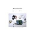
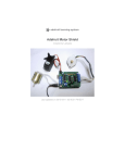
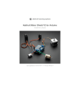
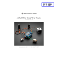
Adafruit Motor Shield
RB-Ada-02
F.A.Q................................................................................................................................... 2
Parts list............................................................................................................................... 4
Assembly............................................................................................................................. 7
Powering your DC motors, voltage and current requirements ......................................... 18
How to set up the Arduino + Shield for powering motors................................................ 19
Servos................................................................................................................................ 21
DC Motors ........................................................................................................................ 23
Steppers............................................................................................................................. 25
F.A.Q.
How many motors can I use with this shield?
You can use 2 DC servos that run on 5V and up to 4 DC motors or 2 stepper motors (or 1 stepper and
up to 2 DC motors)
Can I connect more motors?
No, at this time it is not possible to stack the shield or otherwise connect it up easily to control 4
steppers, for example.
What is the LED for?
The LED indicates motor power. If it is not lit, then the DC/Stepper motors will not run. The servo
ports are 5V powered and does not use the DC motor supply
Im trying to build this robot and it doesn't seem to run on a 9V battery....
Please read the user manual for information about appropriate power supplies
Can this shield control small 3V motors?
Not really, its meant for larger, 6V+ motors. In theory you should be able to get it working with 3V
motors but I have no information on how to do so or whether it will work
What is the power connector on the shield for? How do I power my
motors?
Please read the user manual for information about appropriate power supplies
My Arduino freaks out when the motors are running! Is the shield
broken?
Motors take a lot of power, and can cause 'brownouts' that reset the Arduino. For that reason the shield
is designed for seperate (split) supplies - one for the electronics and one for the motor. Doing this will
prevent brownouts. Please read the user manual for information about appropriate power supplies
I have good solid power supplies, but the DC motors seem to 'cut out' or
'skip'
Try soldering a ceramic or disc 0.1uF capacitor between the motor tabs (on the motor itself!) this will
reduce noise that could be feeding back into the circuit (thanks macegr!)
What pins are not used on the motor shield?
All 6 analog input pins are available. They can also be used as digital pins (pins #14 thru 20)
Digital pin 2, and 13 are not used.
Digital pin 11: DC Motor #1 / Stepper #1
Digital pin 3: DC Motor #2 / Stepper #1
Digital pin 5: DC Motor #3 / Stepper #2
Digital pin 6: DC Motor #4 / Stepper #2
These pins are in use only if the DC/Stepper noted is in use
Digital pin 4, 7, 8 and 12 are used to drive the DC/Stepper motors via the latch
These pins are in use if any DC/steppers are used
Digitals pin 9: Servo #1 control
Digital pin 10: Servo #2 control
These pins are used only if that particular servo is in use
I get the following error trying to run the example code:
"error: AFMotor.h: No such file or directory...."
Make sure you have installed the AFMotor library
How do I install the library?
Download the latest Arduino library file and uncompress the folder. Place the folder AFMotor into the
Arduino/hardware/library folder. That is, find your Arduino install folder, then open up hardware &
library and drag AFMotor into it. Inside AFMotor should be a AFMotor.c and AFMotor.h file
I have two stepper motors and I want to run them simulaneously but the
example code can only control one and then the other?
The stepper motor library step() routine does not have the ability to run both motors at a time. Instead,
you will have to 'interleave' the calls. For example, to have both motors step forward 100 times you
must write code like this:
for (i=0; i<100; i++) {
motor1.step(1, FORWARD, SINGLE);
motor2.step(1, FORWARD, SINGLE);
}
Parts list
Image
Name
PCB
Description
Printed circuit board
Distributor
Qty
Adafruit
1
Digikey
Mouser
2
Digikey
Mouser
1
Digikey
Mouser
1
Digikey
Mouser
1
Digikey
Mouser
1
L293D
Dual H-bridge
IC1,
IC2
IC3
* See note on usage page
for replacing with
SN754410
74HC595N
Serial to parallel output
latch
3mm LED, any color
LED1
Motor power indicator
1.5K resistor for LED1
R1
Brown Green Red Gold
R2
10K pulldown resistor
Brown, Black, Orange,
Gold
RN1
10-pin bussed 10K-100K
resistor network
Digikey
Mouser
1
C2,
C4,
C6
0.1uF ceramic capacitor
Digikey
Mouser
3
C1,
C3,
C5
100uF / 6V capacitor
Digikey
Mouser
3
C7,
C8
47uF / 25V capacitor
Digikey
Mouser
2
Mouser
2
Mouser
1
5-position 5.08 terminal
block
X1
(Or a 3-position and a 2position)
X2
2-position 5.08 terminal
block
RESET
6mm tactile switch
Digikey
Mouser
1
PWR
Jumper/shunt
Digikey
Mouser
1
36 pin male header (1x36)
Digikey
Mouser
1
Assembly
First, check that you have all the parts! Look over the parts list
shown on the left. Also check to make sure you have the
necessary tools for assembly.
Place the motor shield PCB in a vise or other circuit-board holder
and turn on your soldering iron to 700 degrees.
The firt parts to go in are the two resistors, R1 and R2. Bend the
resistors so that they look like staples, as seen in this photo
Next, slip the resistors into the PCB as shown, so that they sit flat
against the circuit board. Bend the wire legs out a bit so that when
the board is flipped over
Resistors are not polarized, that means you can put them in "either
way" and they'll work just fine.
Using your soldering iron tip, heat the resistor wire lead and the
metal ring (pad) at the same time, after a few seconds, poke a little
solder in so that it melts into a nice cone. Remove the solder and
then remove the soldering iron. Do this for all 4 wires.
Check your work, you should have clean solder joints
Clip the long leads, just above the solder joint using diagonal
cutters
Next place the three yellow ceramic capacitors C4, C2 and C6.
Ceramic capacitors are not polarized so you can put them in
"either way" and they work fine.
Bend the leads out just like you did with the resistors.
Solder all 6 wires, then clip them as you did with the resistors.
Next is the 6mm tactile switch RESET and the resistor network
RN1. The tact switch is used to reset the Arduino since its not
possible to reach the reset button once the motor shield is on.
The resistor network is used to pull-down the pins on the motor
driver chips so that they don't power up the motors before the
Arduino sketch tells them to.
The tactile switch can go in 'either way'. The resistor network,
however, must go in a certain way. Make sure the end with a dot
is posititioned so it is at the same end as the X in the silkscreened
image of the resistor network. (See picture on left)
Flip the board over and solder in the resistor network and switch.
You won't need to clip the leads as they are quite short aleady.
Next are the three integrated circuits (ICs) IC1, IC2 and IC3.
When ICs come from the factory, the legs are angled out
somewhat which makes it difficult to insert them into the PCB.
Prepare them for soldering by gently bending the legs against a
flat tabletop so that they are perfectly straight.
ICs must be placed in the correct orientation to work properly. To
help with placement, each chip has a U notch at the top of the
chip. On the circuit board there is a printed out image of the chip
outline and one end has a U notch. Make sure the chip notch is on
the same end as the image notch. In this PCB, all are facing the
same way.
Gently insert the three chips. Check to make sure none of the legs
got bent or broken.
The 74HC595 goes in the middle, and the two L293Ds go on
either side.
Solder each pin of the chips.
The four 'middle' pins of the L293D motor driver chips are tied to
a large heat sink and thus may end up getting 'bridged' with solder
as shown in the second image.
Next are the three 100uF electrolytic capacitors C1, C3 and C5.
Electrolytic capacitors are polarized and must be placed in the
correct orientation or they could pop! The long leg of the
capacitor is the positive (+) leg and goes into the hole marked
with a +. The close-up images shown here indicate with hole is
the + one.
After double-checking their polarity, solder and clip the three
capacitors
Place the two 47uF remaining electrolytic capacitors, C7 and C8
These are also polarized so make sure the long lead is inserted
into the + hole in the silkscreened image.
Solder and clip the two capacitors
Next is the 3mm LED used to indicate motor power. LEDs are
polarized, just like capacitors, and the long lead is the positive (+)
lead.
Make sure the LED is placed correctly otherwise it wont work!
Solder and clip the LED leads.
Next its time to make the headers for the jumper, servos and
arduino.
We use one stick of 36-pin 'breakaway' header, and break it apart
to make smaller strips. You can use diagonal cutters or pliers to
snap off the pieces.
Break the 36-pin header into 2 8-pin, 2 6-pin, 2 3-pin and 1 2-pin
headers.
If you have an NG arduino, you may want 1 6-pin header and 1 4pin header instead of 2 6-pin headers.
The 2 3-pin pieces go in the servo connections in the top left
corner. The 2-pin piece goes in the PWR jumper in the bottom
center.
Also, place the 3 large screw terminals for the motor and external
motor-power wires. If you received only 2 and 3-position terminal
blocks, slide them together so that you have 2 5-position terminals
and 1 2-position terminal.
Solder in the 3 pieces of header and the three terminal blocks
Next, place the 8-pin and 6-pin headers into the Arduino board.
This will make sure that the headers are perfectly lined up. Make
sure the Arduino is not plugged in or powered!
Place the motor shield on top of the Arduino, making sure that all
the header lines up.
Solder in each pin of the header.
You're done!
Powering your DC motors, voltage and current
requirements
Motors need a lot of energy, especially cheap motors since they're less efficient. The first important
thing to figure out what voltage the motor is going to use. If you're lucky your motor came with some
sort of specifications. Some small hobby motors are only intended to run at 1.5V, but its just as
common to have 6-12V motors. The motor controllers on this shield are designed to run from 4.5V to
36V. (However, in theory they should be OK down to about 2.5V?)
Current requirements: The second thing to figure out is how much current your motor will need.
The motor driver chips that come with the kit are designed to provide up to 600 mA per motor, with
1.2A peak current. If you need more current you can 'double up' the motor (connect your motor to two
ports at once) for 1.2A per motor, 2.4A peak. Note that once you head towards 1A you'll probably
want to put a heatsink on the motor driver, otherwise you will get thermal failure, possibly burning out
the chip.
On using the SN754410: Some people use the SN754410 motor driver chip because it is pincompatible, has output diodes and can provide 1A per motor, 2A peak. After careful reading of the
datasheet and discussion with TI tech support and power engineers it appears that the output diodes
were designed for ESD protection only and that using them as kickback-protection is a hack and not
guaranteed for performance. For that reason the kit does not come with the SN754410 and instead
uses the L293D with integrated kickback-protection diodes. If you're willing to risk it, and need the
extra currrent, feel free to buy SN754410's and replace the provided chips.
Need more power? Buy another set of L293D drivers and solder them right on top of the ones on the
board (piggyback). Voila, double the current capability!
You can't run motors off of a 9V battery so don't even waste your time/batteries! Use a big Lead
Acid or NiMH battery pack. It’s also very much suggested that you set up two power supplies (split
supply) one for the Arduino and one for the motors. 99% of 'weird motor problems' are due to noise
on the power line from sharing power supplies and/or not having a powerful enough supply!
How to set up the Arduino + Shield for powering motors
Servos are powered off of the same regulated 5V that the Arduino uses. This is OK for the small
hobby servos suggested. If you want something beefier, cut the trace going to + on the servo
connectors and wire up your own 5-6V supply!
The DC motors are powered off of a 'high voltage supply' and NOT the regulated 5V. Don't connect
the motor power supply to the 5V line. This is a very, very bad idea unless you are sure you know
what you're doing!
There are two places you can get your motor 'high voltage supply' from. One is the DC jack on the
Arduino board and the other is the 2-terminal block on the shield that is labeled EXT_PWR. The DC
Jack on the Arduino has a protection diode so you won't be able to mess things up too bad if you plug
in the wrong kind of power. However the EXT_PWR terminals on the shield do not have a
protection diode (for a fairly good reason). Be utterly careful not to plug it in backwards or you
will destroy the motor shield and/or your Arduino!
Here's how it works:
If you would like to have a single DC power supply for the Arduino and motors, simply plug it into
the DC jack on the Arduino or the 2-pin PWR_EXT block on the shield. Place the power jumper on
the motor shield.
If you have a Diecimila Arduino, set the Arduino power source jumper to EXT.
Note that you may have problems with Arduino resets if the battery supply is not able to provide
constant power, and it is not a suggested way of powering your motor project
If you would like to have the Arduino powered off of USB and the motors powered off of a DC
power supply, plug in the USB cable. Then connect the motor supply to the PWR_EXT block on the
shield. Do not place the jumper on the shield. This is a suggested method of powering your motor
project (If you have a Diecimila Arduino, don't forget to set the Arduino power jumper to USB. If you
have a Diecimila, you can alternately do the following: plug the DC power supply into the Arduino,
and place the jumper on the motor shield.)
If you would like to have 2 separate DC power supplies for the Arduino and motors. Plug in the
supply for the Arduino into the DC jack, and connect the motor supply to the PWR_EXT block. Make
sure the jumper is removed from the motor shield. If you have a Diecimila Arduino, set the Arduino
jumper to EXT. This is a suggested method of powering your motor project. Either way, if you want
to use the DC motor/Stepper system the motor shield LED should be lit indicating good motor power
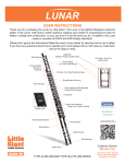
Servos
Hobby servo
Hobby servos are the easiest way to get going with motor control. They have a 3-pin 0.1" female
header connection with +5V, ground and signal inputs. The motor shield simply brings out the 16bit
PWM output lines to 2 3-pin headers so that it’s easy to plug in and go. They can take a lot of power
so a 9V battery won’t last more than a few minutes!
The nice thing about using the onboard PWM is that it’s very precise and goes about its business in
the background. You can use the ServoTimer1 library as is
Using the servos is easy:
1. Install the ServoTimer1 library as indicated on its webpage
2.
3.
4.
5.
Make sure you include <ServoTimer1.h>
Create a ServoTimer1 object for each servo you want (up to 2)
Attach the servos to pin 9 (servo A) or 10 (servo B) using attach()
Finally, when you want to set the position of the servo, simply use write(ANGLE) where
ANGLE ranges from 0 to 180. 90 is "dead center" for position-servos and "not moving" for
continuous-rotation servos.
#include <ServoTimer1.h>
ServoTimer1 servo1;
ServoTimer1 servo2;
void setup() {
Serial.begin(9600);
//
set up Serial library at 9600 bps
Serial.println("Servo test!");
servo1.attach(10);
servo2.attach(9);
}
void loop() {
Serial.print("tick");
servo1.write(180);
servo2.write(0);
delay(1000);
Serial.print("tock");
servo1.write(0);
servo2.write(180);
delay(1000);
}
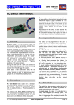
DC Motors
DC motor
DC motors are used for all sort of robotic projects. The motor shield can drive up to 4 DC motors bidirectionally. That means they can be driven forwards and backwards. The speed can also be varied at
0.5% increments using the high-quality built in PWM. This means the speed is very smooth and won't
vary!
Note that the H-bridge chip is not really meant for driving loads over 0.6A or that peak over 1.2A so
this is for small motors. Check the datasheet for information about the motor to verify its OK.
To connect a motor, simply solder two wires to the terminals and then connect them to either the M1,
M2, M3, or M4. Then follow these steps in your sketch
1. Make sure you include <AFMotor.h>
2. Create the AF_DCMotor object with AF_DCMotor(motor#, frequency), to setup the motor
H-bridge and latches. The constructor takes two arguments.
3. The first is which port the motor is connected to, 1, 2, 3 or 4.
frequency is how fast the speed controlling signal is.
4. For motors 1 and 2 you can choose MOTOR12_64KHZ, MOTOR12_8KHZ,
MOTOR12_2KHZ, or MOTOR12_1KHZ. A high speed like 64KHz wont be audible but a
low speed like 1KHz will use less power. Motors 3 & 4 are only possible to run at 1KHz and
will ignore any setting given
5. Then you can set the speed of the motor using setSpeed(speed) where the speed ranges from
0 (stopped) to 255 (full speed). You can set the speed whenever you want.
6. To run the motor, call run(direction) where direction is FORWARD, BACKWARD or
RELEASE. Of course, the Arduino doesn't actually know if the motor is 'forward' or
'backward', so if you want to change which way it thinks is forward, simply swap the two
wires from the motor to the shield.
#include <AFMotor.h>
AF_DCMotor motor(2, MOTOR12_64KHZ);
// create motor #2, 64KHz pwm
void setup() {
Serial.begin(9600);
//
set up Serial library at 9600 bps
Serial.println("Motor test!");
motor.setSpeed(200);
the speed to 200/255
}
// set
void loop() {
Serial.print("tick");
motor.run(FORWARD);
it on going forward
delay(1000);
Serial.print("tock");
motor.run(BACKWARD);
other way
delay(1000);
Serial.print("tack");
motor.run(RELEASE);
stopped
delay(1000);
}
// turn
// the
//
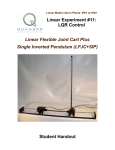
Steppers
A bi-polar stepper motor - 4 wires
Stepper motors are great for (semi-)precise control, perfect for many robot and CNC projects. This
motor shield supports up to 2 stepper motors. The library works identically for bi-polar and uni-polar
motors
For unipolar motors: to connect up the stepper, first figure out which pins connected to which coil, and
which pins are the center taps. If its a 5-wire motor then there will be 1 that is the center tap for both
coils. There’s plenty of tutorials online on how to reverse engineer the coils pinout. The
center taps should both be connected together to the GND terminal on the motor shield output block.
then coil 1 should connect to one motor port (say M1 or M3) and coil 2 should connect to the other
motor port (M2 or M4).
For bipolar motors: its just like unipolar motors except there’s no 5th wire to connect to ground. The
code is exactly the same.
Running a stepper is a little more intricate than running a DC motor but its still very easy
1. Make sure you include <AFMotor.h>
2. Create the stepper motor object with AF_Stepper(steps, stepper#) to setup the motor Hbridge and latches. Steps indicates how many steps per revolution the motor has. a
7.5degree/step motor has 360/7.5 = 48 steps. Stepper# is which port it is connected to. If
you're using M1 and M2, its port 1. If you're using M3 and M4 its port 2
3. Set the speed of the motor using setSpeed(rpm) where rpm is how many revolutions per
minute you want the stepper to turn.
4. Then every time you want the motor to move, call the step(#steps, direction, steptype)
procedure. #steps is how many steps you'd like it to take. direction is either FORWARD or
BACKWARD and the step type is SINGLE, DOUBLE. INTERLEAVE or MICROSTEP.
"Single" means single-coil activation, "double" means 2 coils are activated at once (for higher
torque) and "interleave" means that it alternates between single and double to get twice the
resolution (but of course its half the speed). "Microstepping" is a method where the coils are
PWM'd to create smooth motion between steps. There’s tons of information about the
pros and cons of these different stepping methods in the resources page.
You can use whichever stepping method you want, changing it "on the fly" to as
you may want minimum power, more torque, or more precision.
5. By default, the motor will 'hold' the position after its done stepping. If you want to release all
the coils, so that it can spin freely, call release()
6. The stepping commands are 'blocking' and will return once the steps have finished. If
someone wants to be awesome and write a version of the library that does background
stepping that would be cool! :)
#include <AFMotor.h>
AF_Stepper motor(48, 2);
void setup() {
Serial.begin(9600);
//
set up Serial library at 9600 bps
Serial.println("Stepper test!");
motor.setSpeed(10);
// 10 rpm
motor.step(100, FORWARD, SINGLE);
motor.release();
delay(1000);
}
void loop() {
motor.step(100, FORWARD, SINGLE);
motor.step(100, BACKWARD,
SINGLE);
motor.step(100, FORWARD, DOUBLE);
motor.step(100, BACKWARD,
DOUBLE);
motor.step(100, FORWARD,
INTERLEAVE);
motor.step(100, BACKWARD,
INTERLEAVE);
motor.step(100, FORWARD,
MICROSTEP);
motor.step(100, BACKWARD,
MICROSTEP);
}
If you want two stepper motors to step at once you'll need to write something like this:
void doublestep (int steps, int
direction, int style) {
while (steps--) {
motor1.step(1, direction,
style);
motor2.step(1, direction,
style);
}
}