1
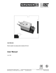
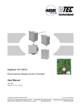
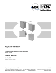
PolyGard Gas Controller DGC3 Digital Gas Controller for up to 16 Gas Transmitters User Manual July 2011 September 17, 2013 – Revision Polygard® is a registered trademark of MSR Customer Services (858) 578-7887 & (888) GO INTEC Fax (858) 578-4633 & (888) FX INTEC www.inteccontrols.com INTEC Controls, 12700 Stowe Dr., Suite 100, Poway, CA 92064 DGC3 Specification subject to change without notice. Printed in USA 130917 PolyGard® Digital Gas Controller User Manual - DGC3 Page 02 1 2 Intended Use .......................................................................................................................................... 3 Operating Instruction ............................................................................................................................ 4 2.1 Description Keypad User Interface ................................................................................................... 4 2.2 Setting / Changing Parameters or Set points .................................................................................... 4 2.3 Code Levels...................................................................................................................................... 5 3 Menu Overview ...................................................................................................................................... 5 3.1 Fault Management ............................................................................................................................ 6 3.1.1 Acknowledge a Fault ................................................................................................................. 6 3.1.2 Error Memory ............................................................................................................................ 6 3.1.3 System Errors ............................................................................................................................ 7 3.2 Status Alarm ..................................................................................................................................... 8 3.3 Status Relay ..................................................................................................................................... 8 3.3.1 Manual Operation of the Relays ................................................................................................ 8 3.4 Menu Measuring Values ................................................................................................................... 9 3.5 Menu Relay Parameters ................................................................................................................. 10 3.5.1 Relay Mode ............................................................................................................................. 11 3.5.2 Relay Function Static / Flash ................................................................................................... 11 3.5.3 Latching Mode ......................................................................................................................... 11 3.5.4 Horn Function .......................................................................................................................... 12 3.5.5 External Relay Operation......................................................................................................... 13 3.5.6 Delay Mode of the Relay. ........................................................................................................ 13 3.6 Menu MP Parameters ..................................................................................................................... 13 3.6.1 Activate – Deactivate MP......................................................................................................... 15 3.6.2 Selection Gas Type ................................................................................................................. 15 3.6.3 Measuring Range .................................................................................................................... 16 3.6.4 MP Signal ................................................................................................................................ 16 3.6.5 Threshold / Hysteresis ............................................................................................................. 16 3.6.6 Delay of Alarm ON or OFF ...................................................................................................... 16 3.6.7 Control Mode ........................................................................................................................... 17 3.6.8 MP Fault Assigned to Alarm .................................................................................................... 17 3.6.9 Alarm Assigned to Alarm Relay ............................................................................................... 17 3.6.10 MP Signal Assigned to Analog Output ..................................................................................... 17 3.7 Menu System Parameters .............................................................................................................. 18 3.7.1 Service Mode .......................................................................................................................... 19 3.7.2 Software Version ..................................................................................................................... 19 3.7.3 Maintenance Concept .............................................................................................................. 19 3.7.4 Average Function .................................................................................................................... 20 3.7.5 Customer Password (Code 4) ................................................................................................. 20 3.7.6 Analog Output ......................................................................................................................... 20 3.7.7 Define the Fault Relay ............................................................................................................. 20 3.7.8 Power On Time ....................................................................................................................... 21 3.7.9 Registration of Extension Modules .......................................................................................... 21 3.7.10 Error Indicator System Bus ...................................................................................................... 21 4 Notes and General Information........................................................................................................... 22 4.1 Intended Product Application .......................................................................................................... 22 4.2 Installers` Responsibilities .............................................................................................................. 22 4.3 Maintenance ................................................................................................................................... 22 4.4 Limited Warranty ............................................................................................................................ 22 Polygard® is a registered trademark of MSR Customer Services (858) 578-7887 & (888) GO INTEC Fax (858) 578-4633 & (888) FX INTEC www.inteccontrols.com INTEC Controls, 12700 Stowe Dr., Suite 100, Poway, CA 92064 DGC3 Specification subject to change without notice. Printed in USA 130917 PolyGard® Digital Gas Controller User Manual - DGC3 Page 03 Digital Gas Controller DGC3 1 Intended Use The PolyGard® measuring, controlling and evaluating system DGC3 (Digital Gas Controller) is used for the detecting and warning of toxic and combustible gases and vapours in the ambient air, mainly in multi-story buildings and underground car parks. The DGC3 Gas Controller fulfills the requirements according to VDI 2053 (January 04), German regulations for car parks, ÖNORM and NVN 2443 for the stationary monitoring of carbon monoxide (CO), nitrogen dioxide (NO2) and combustible gases. The Gas Controller is suitable for the connection of up to 16 digital gas transmitters of the DT5 series. Up to four alarm thresholds are free programmable per measuring point (MP). Each alarm threshold can be assigned to one of the maximum 14 alarm relays (RX). With its up to 5 analog output signals (4-20 mA) the Gas Controller can be used for the continuously various activation of frequency converters etc. The free adjustable parameters and alarm threshold enable a very flexible use in the gas measuring technique. Simple and comfortable commissioning is possible thanks to the configuration with preset parameters. Configuration, parameter settings and operation are done via the logical, easy system menu structure without specific programming knowledge. The intended sites within the ambient conditions as specified in the Technical Data are all areas being directly connected to the public low voltage supply, e.g. residential, commercial and industrial ranges as well as small enterprises (according to EN50 082). The PolyGard® Gas Controller DGC3 must not be used in potentially explosive atmospheres. Prior to commissioning, it is essential to consider the included guidelines for wiring and commissioning of this hardware. Polygard® is a registered trademark of MSR Customer Services (858) 578-7887 & (888) GO INTEC Fax (858) 578-4633 & (888) FX INTEC www.inteccontrols.com INTEC Controls, 12700 Stowe Dr., Suite 100, Poway, CA 92064 DGC3 Specification subject to change without notice. Printed in USA 130917 PolyGard® Digital Gas Controller User Manual - DGC3 2 Page 04 Operating Instruction The complete configuration, parameterization and service are made via keypad user interface in combination with the display screen. Security is provided via four password levels against unauthorised intervention. Alarm 1 Alarm 2 INTEC Controls DGC3 2.1 Description Keypad User Interface Exits programming and saves settings, returns to the previous menu level. Enters submenus, save setting. Scrolls up in main menu and submenus, increases or decreases a value. Moves the cursor. LED orange: Flashes when alarm one or more alarms are active. Permanently on, when at least one relay is manually operated. LED red: Flashes when alarm two or more alarms are active. Permanently on, when at least one relay is manually operated. LED yellow: Flashes at system or sensor failure or when maintenance needed. LED green: Power LED 2.2 Setting / Changing Parameters or Set points Open desired menu window. Code window opens, if no code level approved. After inputting the valid code the cursor jumps on the first position segment to be changed. Push the cursor onto the position segment, which is to be changed. Change the parameter / set point. Save the changed value. Finished Polygard® is a registered trademark of MSR Customer Services (858) 578-7887 & (888) GO INTEC Fax (858) 578-4633 & (888) FX INTEC www.inteccontrols.com INTEC Controls, 12700 Stowe Dr., Suite 100, Poway, CA 92064 DGC3 Specification subject to change without notice. Printed in USA 130917 PolyGard® Digital Gas Controller User Manual - DGC3 2.3 Page 05 Code Levels All inputs and changes are protected by a four-digit numeric code (= password) against unauthorised intervention. All menu windows are visible without entering a code. Level 1: (1234) Code level 1 allows the operator to acknowledge alarms and to manually activate the alarm relays. Level 2: Code level is intended for the service technician to change parameters and set-points. Level 3: With code level 3 it is possible to register and deregister transmitters in addition to code level 1. This code is released by MSR only in emergency situations. Level 4: Code level 4 is intended for updating the maintenance date. Normally the code is only known by the service technician and can be changed individually via code level 2. The release of a code level is cancelled if no button is pushed within 15 minutes. 3 Menu Overview The operation of the Gas Controller DGC3 is done via a simple and logical menu structure which is easy to learn. The operating menu contains the following levels: Starting menu: Scrolling of the measuring points of all registered transmitters in 10-second intervals. Main menu Submenu 1 and 2 Starting menu Main menu Submenu INTEC Controls DGC3 System Errors Status Alarm Status Relay Measuring Values Relay Parameter MP Parameter System Parameter Display and reset of errors See from point 3.1 Displays the status of actual alarms See point 3.2 Display of the relay status Manual operation of the relays Reset function of the relays See from point 3.3 Displays the measured values See point 3.4 Display and change of the relay parameters See from point 3.5 Display and change of the measuring point parameters Activate or deactivate MP Assignment of the alarms to the alarm relays See from point 3.6 Display and change of the system parameters See from point 3.7 Polygard® is a registered trademark of MSR Customer Services (858) 578-7887 & (888) GO INTEC Fax (858) 578-4633 & (888) FX INTEC www.inteccontrols.com INTEC Controls, 12700 Stowe Dr., Suite 100, Poway, CA 92064 DGC3 Specification subject to change without notice. Printed in USA 130917 PolyGard® Digital Gas Controller User Manual - DGC3 3.1 Page 06 Fault Management The integrated fault management records the last 15 faults in the menu “System Errors” with a stamp indicating how many days the error has already existed. The day counter subtracts active ones from 365. Additionally a record of the faults occurs in the “Error Memory”, which can be selected and reset only by the service technician. An actual fault is displayed in plain text in the starting menu. The failure relay which is defined in the system parameter “Failure relay” is activated. The yellow LED in the front of the gas controller flashes. In case of fault of a measuring point (MP) the alarms defined in the menu “MP Parameter” are activated additionally. 3.1.1 Acknowledge a Fault Attention: Acknowledging a fault is only possible after having removed the cause. System Errors Select menu “System Errors” MP 01.1 Tage Error 365 Example: Communication error MP 01.1 MP 01.1 Reset ?? Error Reset the fault? Fault reset MP 01.1 Error Erased Fault reset 3.1.2 or Error still exists Cause not eliminated Reset not possible Error Memory The menu “Error Memory” in the main menu “System Error” can only be opened via code level 2. In the error memory the last 15 faults even those already acknowledged in the menu “System Error” are listed for the service technician. The deletion of each individual message is effected in the same way as the reset of a fault. Polygard® is a registered trademark of MSR Customer Services (858) 578-7887 & (888) GO INTEC Fax (858) 578-4633 & (888) FX INTEC www.inteccontrols.com INTEC Controls, 12700 Stowe Dr., Suite 100, Poway, CA 92064 DGC3 Specification subject to change without notice. Printed in USA 130917 PolyGard® Digital Gas Controller User Manual - DGC3 3.1.3 Page 07 System Errors The following system error messages are recorded: MP XX.1 Error Communication error to transmitter MP XX.1 Cause: Bus line interrupted or short-circuited. MP XX.1 registered at the controller, but not addressed, transmitter defective. Solution: Check line to transmitter, check transmitter address, replace transmitter MP XX.1 Overrange MP XX.1 Underrange Sensor signal at the transmitter out of the measuring range. Cause: Transmitter not calibrated, defective. Solution: Calibrate transmitter, replace transmitter. MP XX.2 > 22 mA Current signal at analog input for transmitter MP XX > 22 mA. Cause: Short-circuit at analog input, AT transmitter not calibrated, defective. Solution: Check cable to AT transmitter, perform calibration, replace AT transmitter. MP XX.2 < 3 mA Current signal at analog input MP XX < 3 mA. Cause: Wire break at analog input, AT transmitter not calibrated, defective. Solution: Check cable to AT transmitter, perform calibration, replace AT transmitter. GC Error: Internal communication error I/O Board to LCD Board. Cause: Internal error. Solution: Replace the Gas Controller. EP 0X Error Communication error to expansion module EP 0X. (Only active, if EP 0X is registered). Cause: EP module address not correct. (See Commissioning) Bus cable to EP 0X module interrupted. No power supply at the EP 0X module. EP module defective. Solution: Check and correct the EP module address. Check bus line and power supply. Replace EP 0X module. Maintenance: System maintenance is necessary. Cause: Maintenance date exceeded. Solution: Perform maintenance. Polygard® is a registered trademark of MSR Customer Services (858) 578-7887 & (888) GO INTEC Fax (858) 578-4633 & (888) FX INTEC www.inteccontrols.com INTEC Controls, 12700 Stowe Dr., Suite 100, Poway, CA 92064 DGC3 Specification subject to change without notice. Printed in USA 130917 PolyGard® Digital Gas Controller User Manual - DGC3 3.2 Page 08 Status Alarm Display of the actual alarms in plain text in the order of their arrival. Only those measuring points are displayed, where at least one alarm is active. Changes are not possible in this menu. MP 02.1 A1 A2 Symbol MP 02 AX 3.3 Description Measuring Point No. Status alarm Function A1 = A2 = A3 = A4 = Alarm 1 Alarm 2 Alarm 3 Alarm 4 ON ON ON ON Status Relay Display of the actual status of alarm relays. Manual operation of the alarm relays. R 01 OFF 3.3.1 Symbol Description R 01 Relay No. 01 OFF Status relay Setting Status OFF Function Select Relay No. = Relay OFF (No gas alarm) OFF = Relay ON (Gas alarm) ON = Relay manual OFF Manual OFF = Relay manual ON Manual ON Manual Operation of the Relays The manual operation of the alarm relays is managed in the menu “Status Relay”. If a relay is in the manual ON or OFF status, the orange/ red alarm LED at the Gas Controller is lit continuously. The external operation of the alarm relay via an assigned digital input has priority to the manual operation in the menu “Status Relay” and to gas alarm. Relays manually operated in the menu “Status Relay” are deleted again by selecting the function “Automatic”. Acknowledging the relays in latching mode is also effected in this menu. R 01 OFF Manual ON Manual OFF Manual OFF Select the relay Select the function of manual operation Select the function Manual ON Manual OFF Automatic Reset? = Relay ON = Relay OFF = Delete manual operation. = Reset of a latching mode. Take over the function Polygard® is a registered trademark of MSR Customer Services (858) 578-7887 & (888) GO INTEC Fax (858) 578-4633 & (888) FX INTEC www.inteccontrols.com INTEC Controls, 12700 Stowe Dr., Suite 100, Poway, CA 92064 DGC3 Specification subject to change without notice. Printed in USA 130917 PolyGard® Digital Gas Controller User Manual - DGC3 3.4 Page 09 Menu Measuring Values This menu is for displaying the current value (CV) or the average value (AV) with gas unit and gas type for each active measuring point according to the defined mode of control (CV or AV mode). For gas type CO both values are displayed together. MP 01.1 = Measured value of the bus transmitter with MP address 01. MP 01.2 = Measured value of the analog transmitter connected to the bus transmitter via MP address 01. The MP address and the display depend on the installed software. In the version without analog transmitters at the 4 to 20 mA input of the DT- 05 the addresses are listed from MP-01 to MP 16. In the version with additional analog transmitters the addresses are listed from 1 to 8 with the index XX.1 for the measured value of the bus transmitter and with XX.2 for the measured value of the analog transmitter. Display for software version 16 bus transmitters -------------------------------------------------------------------------------------------------------------------------------------------MP 01 MP 01 CO ppm 50 *AV 33 CV Display for software version 8 bus transmitters and 8 analog transmitters -------------------------------------------------------------------------------------------------------------------------------------------MP 01 MP 01.1 CO ppm 50 *AV 33 CV MP 01.2 Ex %LEL 10 AV 13*CV Symbol Description MP 01.1 Measuring point No. MP XX.1 Measured value MP XX.2 Measured value CO ppm CV AV * Not active Error Gas type Gas unit Current value Average value Control mode Status MP Fault MP Default Function Bus transmitter with address 01 Measured value bus transmitter at address XX Measured value analog transmitter at bus transmitter with address XX See 3.6.2 See 3.6.2 Current value of gas concentration Average value (10 measured values within the time unit) Display of selected control mode (CV or AV) MP not active Current signal < 3 mA or > 22 mA Polygard® is a registered trademark of MSR Customer Services (858) 578-7887 & (888) GO INTEC Fax (858) 578-4633 & (888) FX INTEC www.inteccontrols.com INTEC Controls, 12700 Stowe Dr., Suite 100, Poway, CA 92064 DGC3 Specification subject to change without notice. Printed in USA 130917 PolyGard® Digital Gas Controller User Manual - DGC3 3.5 Page 10 Menu Relay Parameters Display and change of the parameters for each alarm relay. Relay Parameter (Main menu) R 01 (Select relay No.) (Relay No. 05 not available in the DGC3 for hardware reasons) Relay Mode De- energized Relay mode See 3.5.1 Static / Flash 0s Relay function See 3.5.2 Latching Mode No Time 0s Quitt. 0 Activate latching mode See 3.5.3 DI 0 External Mode DI: ON = 0: OFF = 0 Delay ON Time 0s Delay OFF Time 0s Definition of horn function See 3.5.4 Definition of external relay operation See 3.5.5 Set time for switch ON delay See 3.5.6 Set time for switch OFF delay See 3.5.6 Polygard® is a registered trademark of MSR Customer Services (858) 578-7887 & (888) GO INTEC Fax (858) 578-4633 & (888) FX INTEC www.inteccontrols.com INTEC Controls, 12700 Stowe Dr., Suite 100, Poway, CA 92064 DGC3 Specification subject to change without notice. Printed in USA 130917 PolyGard® Digital Gas Controller User Manual - DGC3 3.5.1 Page 11 Relay Mode Definition of relay mode: Symbol Description R 01 Relay No. Function Selection of relay DeRelay Mode energized 3.5.2 Setting Status DeDe-energized energized Energized = Alarm ON = Relay ON = Alarm ON = Relay OFF Relay Function Static / Flash Definition of relay function 3.5.3 Symbol Description R 01 Relay No. 0 Function Setting Status Function Selection of relay 0 0 = Relay function static > 0 = Relay function flashing (= Time period in sec.) Impulse / Break = 1:1 Setting Status Function Latching Mode Definition of latching function Symbol Description R 01 Relay No. Selection of relay No Latching Mode No No Yes = Latching mode inactive = Latching mode active Acknowledging a latching relay in the menu “Status Relay” is only possible if the gas concentration is again lower than the alarm threshold including hysteresis. In this case the status latching occurs in the display. Example: Alarm relay R2 with latching mode Alarm 2 On Display in the Menu Status Relay Relay 2 Reset in the Menu Status Relay Gas concentration higher Off R2 Off R2 On R2 On R2 On lower than threshold R2 Latching R2 Off On Off On Off Polygard® is a registered trademark of MSR Customer Services (858) 578-7887 & (888) GO INTEC Fax (858) 578-4633 & (888) FX INTEC www.inteccontrols.com INTEC Controls, 12700 Stowe Dr., Suite 100, Poway, CA 92064 DGC3 Specification subject to change without notice. Printed in USA 130917 PolyGard® Digital Gas Controller User Manual - DGC3 3.5.4 Page 12 Horn Function The alarm relay is defined as horn relay by this parameter with the following possibilities to reset. By pressing any of the 4 push-buttons (only possible in the starting menu). Automatic reset at the end of the fixed time. By an external push-button (assignment of the digital input). The horn function is only activated if at least one of the two parameters (time or digital input) is set. Special function Response After acknowledging the relay (by push-button or externally) time starts. When this time has run out and the alarm is still acting, the relay is set again. Symbol Description R 04 Relay No. Quitt Mode Setting Status Function Selection of relay 0 0 = Reset of the relay after time having run out, or by push-button 1 = Reset of the relay by push-button, after time having run out and when alarm is still acting, relay is set again. (Response function). Time 120 Time for automatic reset function or response function 0 = no reset function DI 0 Assignment, which digital input resets the relay. Acknowledge the horn relay Alarm 4 Relay 4 Acknowledging signal On Of Gas concentration higher lower than threshold Time On Off On Off Special function “Response”. (Return of the horn relay) Alarm 4 Relay 4 Acknowledgingsignal On Off Gas concentration higher Time lower than threshold Time On Off On Off Polygard® is a registered trademark of MSR Customer Services (858) 578-7887 & (888) GO INTEC Fax (858) 578-4633 & (888) FX INTEC www.inteccontrols.com INTEC Controls, 12700 Stowe Dr., Suite 100, Poway, CA 92064 DGC3 Specification subject to change without notice. Printed in USA 130917 PolyGard® Digital Gas Controller User Manual - DGC3 3.5.5 Page 13 External Relay Operation Assignment of the digital input (DI) for external switching of the alarm relay (ON and/or OFF). This function has priority to gas alarm and/or manual switching in the menu “Status Relay”. 3.5.6 Setting Status Function Symbol Description R 01 DI-ON Relay No. External On 0 If digital input closed, relay switches ON DI-OFF External Off 0 If digital input closed, relay switches OFF Relay Selection Delay Mode of the Relay. Delay time ON starts when the alarm is released and/or delay time OFF starts when the alarm returns to normal condition. 3.6 Setting Status Symbol Description R 01 Relay No. 0s Delay Time ON 0s Delay Time OFF 0 Function Relay Selection Mode ON: Relay is only activated at the end of the defined time (sec.) 0 sec. = No delay 0 Mode OFF: Relay is only deactivated at the end of the defined time (sec.) 0 sec. = No delay Menu MP Parameters Display and change of MP parameters including activation of measuring points and assignment of alarm relays The presentation of the MP parameters depends on the installed software. See 3.4 Menu Measuring Values. MP Parameter (Main menu) MP 01 (Selection MP No.) MP 01.1 active MP01.1 = Parameter digital transmitter MP 01.2 active MP01.2 = Parameter analog transmitter MPXX.X Mode active Activate or deactivate MP See 3.6.1 MPXX.X Mode active Define gas type See 3.6.2 Gas type CO Polygard® is a registered trademark of MSR Customer Services (858) 578-7887 & (888) GO INTEC Fax (858) 578-4633 & (888) FX INTEC www.inteccontrols.com INTEC Controls, 12700 Stowe Dr., Suite 100, Poway, CA 92064 DGC3 Specification subject to change without notice. Printed in USA 130917 PolyGard® Digital Gas Controller User Manual - DGC3 Define measuring range See 3.6.3 Adjust signal form of the transmitter See 3.6.4 Page 14 Measuring range 300 ppm MP Signal Linear Define threshold 1 See 3.6.5 Threshold 1 80 ppm Define threshold 2 See 3.6.5 Threshold 2 100 ppm Define threshold 3 See 3.6.5 Threshold 3 120 ppm Define threshold 4 See 3.6.5 Threshold 4 120 ppm Hysteresis See 3.6.5 Hysteresis 15 ppm Set alarm ON delay See 3.6.6 Delay time ON 0s Set alarm OFF delay See 3.6.6 Delay time OFF 0s Define control mode See 3.6.7 C/A Mode CV Assignment MP fault to alarm See 3.6.8 Assignment alarm to alarm relay See 3.6.9 Assignment MP signal to analog output See 3.6.10 Alarm - 1 2 3 4 Fault - 0 0 0 0 A1; A2; A3; A4 01; 02; 03, 04 Analog Output 0 Polygard® is a registered trademark of MSR Customer Services (858) 578-7887 & (888) GO INTEC Fax (858) 578-4633 & (888) FX INTEC www.inteccontrols.com INTEC Controls, 12700 Stowe Dr., Suite 100, Poway, CA 92064 DGC3 Specification subject to change without notice. Printed in USA 130917 PolyGard® Digital Gas Controller User Manual - DGC3 3.6.1 3.6.2 Page 15 Activate – Deactivate MP Symbol Description MP 01 Measuring point Active MP Mode Setting Status Not active Function Selection MP No. Active = Measuring point activated at the controller Not active = Measuring point not activated at the controller Selection Gas Type Assign gas type to attached gas transmitters. Symbol Description MP 01 Measuring point CO Gas type Setting Status CO Gas type CO O2> O3 TOX CO2 RH Temp. R22 R134 R123 R11 R411 R410 R407 R416 R404 R409 R408 R402 R401 VOC ETC Cl2 H2S SO2 Ex O2< NH3 NO2 NO Ex Carbon monoxide Oxygen (increasing)2 Ozone Toxic gas Carbon dioxide4 Humidity Temperature Refrigerant gas Refrigerant gas Refrigerant gas Refrigerant gas Refrigerant gas Refrigerant gas Refrigerant gas Refrigerant gas Refrigerant gas Refrigerant gas Refrigerant gas Refrigerant gas Refrigerant gas Air quality Ethylene oxide Chlorine Hydrogen sulphide Sulphur dioxide Carbon dioxide5 Oxygen (falling)3 Ammonia Nitrogen dioxide Nitrogen oxide Combustible gas Unit Measuring range1 ppm Vol% ppm ppm ppk % r. F. °C ppm ppm ppm ppm ppm ppm ppm ppm ppm ppm ppm ppm ppm ppm ppm ppm ppm ppm ppm Vol% ppm ppm ppm %LEL 0 – 300 0 – 25 0–5 0 – XX 0 – 50 0 – 100 0 – 50 0 – 2000 0 – 300 0 – 300 0 – 300 0 – 300 0 – 300 0 – 300 0 – 300 0 – 300 0 – 2000 0 – 2000 0 – 2000 0 – 2000 0 – 2000 0 – 20 0 – 100 0 – 200 0 – 100 0 – 2000 0 – 25 0 – 300 0 – 25 0 – 50 0 – 100 1 Recommendation without obligation Oxygen measurements: Alarm at increasing concentration 3 Oxygen measurements: Alarm at falling concentration 4 Carbon dioxide measurements with unit ppk (1 vol% = 10 ppk) 5 Carbon dioxide measurements with unit ppm (1 vol% = 10.000 ppm) 2 Polygard® is a registered trademark of MSR Customer Services (858) 578-7887 & (888) GO INTEC Fax (858) 578-4633 & (888) FX INTEC www.inteccontrols.com INTEC Controls, 12700 Stowe Dr., Suite 100, Poway, CA 92064 DGC3 Specification subject to change without notice. Printed in USA 130917 PolyGard® Digital Gas Controller User Manual - DGC3 3.6.3 Page 16 Measuring Range The measuring range can be defined arbitrarily between 10 and 10000. The measuring ranges in the table gas type are only recommendations without obligation. The measuring range must agree with the range of the attached gas transmitter. 3.6.4 MP Signal Gas transmitters using electro-chemical or catalytic beat gas sensors normally produce a linear signal, proportional to the gas concentration. Semiconductor gas sensors produce a non-linear (exponential) signal due to their measuring principle. This signal leads to a non-linear output signal of the gas transmitter. The Gas Controller DGC3 is prepared for both types, for gas transmitters with linear signal as well as for analog transmitters with semiconductor sensor and non-linear signal. The signal type is defined in this menu. 3.6.5 Symbol Description MP 01 Measuring Point Linear MP Signal Setting Status Function Selection of MP No. Linear Linear = Transmitter with linear output signal Non linear = Transmitter with non-linear output signal Threshold / Hysteresis For each measuring point four alarm thresholds are available for free definition. If the gas concentration exceeds the adjusted alarm threshold, the associated alarm is set. If the gas concentration falls below the alarm threshold inclusive hysteresis the alarm is reset again. Unused alarm thresholds have to be defined with full scale value, in order to avoid false alarms. For O2 measurement: Pay attention to the alarm activation at decreasing or increasing concentration! Symbol Description 3.6.6 MP 01 Measuring Point 40 ppm Threshold Default Status 40 80 100 120 15 Function Threshold 1 Threshold 2 Threshold 3 Threshold 4 Hysteresis Selection MP No. Gas concentration > Threshold 1 = Alarm 1 Gas concentration > Threshold 2 = Alarm 2 Gas concentration > Threshold 3 = Alarm 3 Gas concentration > Threshold 4 = Alarm 4 Gas concentration < (Threshold X –Hysteresis) = Alarm X OFF Delay of Alarm ON or OFF Definition of alarm ON and/or alarm OFF delay. The function applies to all alarms of an MP. Default Status Symbol Description MP 01 Measuring Point 0s Delay Time ON 0s Delay Time OFF 0 0 Function Selection of MP No. Gas concentration > Threshold: Alarm is only activated at the end of the fixed time (sec.). 0 sec. = No Delay Gas concentration < Threshold: Alarm is only deactivated at the end of the fixed time (sec.). 0 sec. = No Delay The delayed activation of an existing gas alarm can cause damage to persons and objects. The commissioning technician and/or the operator are solely responsible for the activation. Polygard® is a registered trademark of MSR Customer Services (858) 578-7887 & (888) GO INTEC Fax (858) 578-4633 & (888) FX INTEC www.inteccontrols.com INTEC Controls, 12700 Stowe Dr., Suite 100, Poway, CA 92064 DGC3 Specification subject to change without notice. Printed in USA 130917 PolyGard® Digital Gas Controller User Manual - DGC3 3.6.7 Page 17 Control Mode Definition of the alarm evaluation by means of current (CV) or average value (AV). Symbol MP 01 CV Default Function Status t Measuring Point Selection of MP No. CV = Control by the current gas value Evaluation CV AV = Control by the average gas value Description Current- average value function see: 3.7.4 3.6.8 MP Fault Assigned to Alarm Definition, which alarms are activated in case of a fault at the measuring point. Symbol Description MP 01 Alarm - 1 2 3 4 Fault - 1 1 0 0 Measuring Point 3.6.9 Fault MP Default Status 1100 Function Selection of MP No. 0 = Alarm not set at MP fault 1 = Alarm set at MP fault Alarm Assigned to Alarm Relay Each of the 4 alarms can be assigned to any alarm relay. Unused alarms are not assigned to any alarm relay. Symbol Description MP 01 Measuring Point 1 A1 A2 A3 A4 3.6.10 Default Status Function Selection of MP No. 01 02 03 00 01 = Alarm 1 activates alarm relay R 01 02 = Alarm 2 activates alarm relay R 02 03 = Alarm 3 activates alarm relay R 03 04 = Alarm 4 doesn’t activate any alarm relay MP Signal Assigned to Analog Output The measuring point signal can be assigned to the analog output. At this the signal defined in the control mode (current or average value) is transmitted. Analog output see also: 3.7.2 Symbol Description MP 01 Measuring Point 0 A Default Status 0 Function Selection of MP No. 0 = MP Signal not assigned to analog output 1 = MP Signal assigned to analog output 1 Polygard® is a registered trademark of MSR Customer Services (858) 578-7887 & (888) GO INTEC Fax (858) 578-4633 & (888) FX INTEC www.inteccontrols.com INTEC Controls, 12700 Stowe Dr., Suite 100, Poway, CA 92064 DGC3 Specification subject to change without notice. Printed in USA 130917 PolyGard® Digital Gas Controller User Manual - DGC3 3.7 Page 18 Menu System Parameters Displays and changes the system parameters of the Gas Controller module. System Parameter (Main Menu) Service Mode OFF See 3.7.1 Software Version DGC03- XX See 3.7.2 Maintenance due in days 211 See 3.7.3 Service Phone +49/(0)8531/90040 See 3.7.3 AV Overlay 120 s. 120 ppm See 3.7.4 AV Time 1800 s See 3.7.4 Maintenance interval Days: 365 See 3.7.3 Customer Pass Change **** See 3.7.5 Failure Relay XX See 3.7.7 Power On Time 30 s See 3.7.8 EP Module 1 Inactive See 3.7.9 EP Module 2 Inactive See 3.7.9 Polygard® is a registered trademark of MSR Customer Services (858) 578-7887 & (888) GO INTEC Fax (858) 578-4633 & (888) FX INTEC www.inteccontrols.com INTEC Controls, 12700 Stowe Dr., Suite 100, Poway, CA 92064 DGC3 Specification subject to change without notice. Printed in USA 130917 PolyGard® Digital Gas Controller User Manual - DGC3 Correct 0 - Error 0 Page 19 See 3.7.10 Analog Output 3.7.1 Analog Output 1 Max. See 3.7.6 Calibration AO 1 Siehe 4.0=4 mA 20 = 20.0 See 3.7.6 Analog Output 3 to 6 Analog Output 3-6 Service Mode When the service mode is active (ON) the alarms are not transmitted to the alarm relays (in case of calibration or service work). The service mode ON is reset automatically after 60 minutes or manually in the menu “Service Mode”. 3.7.2 3.7.3 Symbol Description Default Status Function Off Service Mode Off Off = Alarms activate the associated alarm relays On = Alarms are not transmitted to the alarm relays Default Status Function Software Version Symbol Description DGC03XX Software Version XX = Software Version Maintenance Concept Integrated in the DGC3 system, there is a control of the maintenance intervals as required by law or by the customer. At commissioning or after maintenance the number of days until the next due maintenance is entered = Reset of the maintenance message (service phone no.). When the days counter reaches zero, the failure signal is activated the following morning at 9 o’clock, and the phone no. of the service technician occurs in the display. The remaining days until the next maintenance can be read from the menu “Maintenance in”. The service phone no. can be entered individually in the next menu. Symbol Description XXX Maintenance in XXX Maintenance interval 0853.... Phone No. Default Status Function Remaining days until the next maintenance Reset of the maintenance message by entering the number of days until the next maintenance Input of the individual service phone no. Polygard® is a registered trademark of MSR Customer Services (858) 578-7887 & (888) GO INTEC Fax (858) 578-4633 & (888) FX INTEC www.inteccontrols.com INTEC Controls, 12700 Stowe Dr., Suite 100, Poway, CA 92064 DGC3 Specification subject to change without notice. Printed in USA 130917 PolyGard® Digital Gas Controller User Manual - DGC3 3.7.4 Page 20 Average Function For each active measuring point the Gas Controller module calculates the arithmetic average value out of 10 measurements got within the time unit defined in the menu “AV Time”. This average value is indicated in the menu “Measuring Values” next to the current value. At each measuring point the control mode (current or average value) is defined for the alarm evaluation. The alarm evaluation of the control mode average value is overlaid by the current value, when the current value exceeds the alarm threshold defined in the menu “AV Overlay”. The overlay is delayed by the time factor defined in this menu. With time factor 0 sec. the overlay is not active. Symbol Description 120 s AV Overlay 120 ppm 1800 s AV Time 3.7.5 Default Status 120 s 120 ppm 1800 s Function sec. = Delay time of average value overlay. 0 = No overlay function ppm = Alarm threshold of average overlay sec. = Time for the calculation of the average value Customer Password (Code 4) Change the system password for level 4 Symbol Description XXXX Customer Password 3.7.6 Default Status Function XXXX = Definition of an individual 4-digit customer’s password (level 4) Analog Output The Gas Controller has up to 5 analog outputs (AO) with 4 to 20 mA signal. The signal of one or more measuring points can be assigned to each analog output. The assignment is performed in the menu “MP Parameters” for each MP. The measuring point sends the signal as defined in the menu “C/A Mode” (CV or AV). Out of the signals of all assigned measuring points the Gas Controller module determines the minimum, the maximum or the average value and transmits it to the analog output. The definition, which value is transmitted, is effected in the menu “Analog Output X”. In mA mode, each analog output can be calibrated at 4 or at 20 mA. Therefore an ampere meter (measuring range 25 mA) can be attached to the AO and the respective factor has to be changed until the analog output corresponds to 4 or 20 mA. During calibration evaluation of the measuring point signals is not possible. This calibration is effected by the factory. The factors shall not be changed. Default Status Symbol Description Max. Select Max. Output Mode 4.0 20.0 Calibration 3.7.7 4.0 20.0 Function Min. = Displays the minimum value of all assigned MP Max. = Displays the maximum value of all assigned MP Average = Displays the average value of all assigned MP 4. 20.0 = Calibration factor at 4 mA = Calibration factor at 20 mA Define the Fault Relay Definition of the fault relay. See also fault management (3.1) Symbol Description X Fault Relay Default Status RX Function RX = Define the fault relay Polygard® is a registered trademark of MSR Customer Services (858) 578-7887 & (888) GO INTEC Fax (858) 578-4633 & (888) FX INTEC www.inteccontrols.com INTEC Controls, 12700 Stowe Dr., Suite 100, Poway, CA 92064 DGC3 Specification subject to change without notice. Printed in USA 130917 PolyGard® Digital Gas Controller User Manual - DGC3 3.7.8 Page 21 Power-On Time Gas sensors need a running-in period, until the chemical process of the sensor reaches stable conditions. During this running-in period the current signal can lead to an unwanted releasing of a pseudo alarm. Therefore the power on time is started at the Gas Controller module after having switched on the power supply. While this time is running out, the Gas Controller does not activate any alarms. The power on status occurs in the starting menu. 3.7.9 Symbol Description 30 s Power On Time Default Status 30 s Function XX = Define the power on time (sec.) Registration of Extension Modules The DGC3 can manage up to two expansion modules EP-05 with five alarm relays each. Each attached EP-05 is registered in this menu. The controller checks the communication to the registered EP-05 modules and shows a fault signal in case of a communication error. In order to recognize the position of the EP-05 modules, a module address is assigned to each module by the address selector. See table. The table shows the assignment of the relay numbers to the individual modules. Symbol Description Not active 3.7.10 EP- Module 1 EP- Module 2 Default Module Function Status Address 1 Not active Active = Module registered Not active = Module not registered Not active 2 Relay No. 05 to 10 11 to 15 Analog Output 03 to 04 05 to 06 Error Indicator System Bus All data packets received by the DGC3 are checked for completeness and compatibility. Faulty data packets are recorded by the error counter. Max. 1-2 faulty data packets are admissible a day. A higher error rate mostly comes from incorrect placement of the field bus line. Polygard® is a registered trademark of MSR Customer Services (858) 578-7887 & (888) GO INTEC Fax (858) 578-4633 & (888) FX INTEC www.inteccontrols.com INTEC Controls, 12700 Stowe Dr., Suite 100, Poway, CA 92064 DGC3 Specification subject to change without notice. Printed in USA 130917 PolyGard® Digital Gas Controller User Manual - DGC3 4 Page 22 Notes and General Information It is important to read this user manual carefully in order to understand the information and instructions. The PolyGard® DGC3 gas monitoring, control and alarm system may only be used for applications in accordance to the intended use. The appropriate operating and maintenance instructions and recommendations must be followed. Due to permanent product developments, MSR reserves the right to change specifications without notice. The information contained herein is based on data considered to be accurate. However, no guarantee or warranty is expressed or implied concerning the accuracy of these data. 4.1 Intended Product Application The PolyGard® DGC3 is designed and manufactured for controlling, for saving energy and keeping OSHA air quality in commercial buildings and manufacturing plants (i.e. detection and automatic exhaust fan control for automotive maintenance facilities, enclosed parking garages, engine repair shops, warehouses with forklifts, fire stations, tunnels, etc.). 4.2 Installers’ Responsibilities It is the installer’s responsibility to ensure that all PolyGard® DGC3 are installed in compliance with all national and local regulations and OSHA requirements. All installations should be executed only by technicians familiar with proper installation techniques, the codes, standards and proper safety procedures for control installations, as well as the latest edition of the National Electrical Code (ANSI/NFPA70). It is also essential to strictly follow all instructions as provided in this user manual. 4.3 Maintenance It is recommended to check the PolyGard® DGC3 system regularly. With regular maintenance deviancies in efficiency can easily be corrected. 4.4 Limited Warranty MSR-Electronic-GmbH and INTEC Controls warrants the PolyGard® DGC3 for a period of two years from the date of shipment against defects in material or workmanship. Should any evidence of defects in material or workmanship occur during the warranty period, INTEC Controls will repair or replace the product at their own discretion, without charge. This warranty does not apply to units that have been altered, had attempted repair, or been subject to abuse, accidental or otherwise. The above warranty is in lieu of all other express warranties, obligations or liabilities. This warranty applies only to the PolyGard® DGC3. MSR-Electronic-GmbH and/or INTEC Controls shall not be liable for any incidental or consequential damages arising out of or related to the use of the PolyGard® DGC3. If the PolyGard® DGC3 needs to be returned to INTEC Controls for service, an RMA number must be obtained prior to sending. Polygard® is a registered trademark of MSR Customer Services (858) 578-7887 & (888) GO INTEC Fax (858) 578-4633 & (888) FX INTEC www.inteccontrols.com INTEC Controls, 12700 Stowe Dr., Suite 100, Poway, CA 92064 DGC3 Specification subject to change without notice. Printed in USA 130917