1
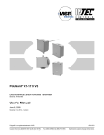
PolyGard AT-1130 V3 Electrochemical Nitrogen Dioxide Transmitter User Manual July, 2011 September 15, 2014 – Revision Polygard® is a registered trademark of MSR Customer Services (858) 578-7887 & (888) GO INTEC Fax (858) 578-4633 & (888) FX INTEC www.inteccontrols.com INTEC Controls, 12700 Stowe Dr., Suite 100, Poway, CA 92064 AT-1130_V3_UserManual Specification subject to change without notice. Printed in USA 140915 PolyGard® NO2 Transmitter User Manual - AT-1130 V3 Page 02 1 General Overview ............................................................................................................................... 3 2 Functional Description ...................................................................................................................... 3 2.1 2.2 3 Installation........................................................................................................................................... 4 3.1 3.2 4 Mounting Instructions ................................................................................................................. 4 Installation .................................................................................................................................. 4 Electrical Connection ......................................................................................................................... 4 4.1 5 Control Mode .............................................................................................................................. 3 Sensor ........................................................................................................................................ 3 Wiring Connection ...................................................................................................................... 4 Commissioning................................................................................................................................... 5 5.1 Calibration .................................................................................................................................. 5 5.2 Manual Calibration...................................................................................................................... 6 5.2.1 Zero-point ................................................................................................................................ 6 5.2.2 Gain......................................................................................................................................... 6 5.2.3 Calculation of Control Voltage ................................................................................................ 6 5.3 Option Relay Output ................................................................................................................... 7 6 Inspection and Service ...................................................................................................................... 8 6.1 6.2 6.3 7 Inspections ................................................................................................................................. 8 Calibration .................................................................................................................................. 8 Exchange of Sensor Element ..................................................................................................... 8 Troubleshooting ................................................................................................................................. 8 7.1 Analog Mode .............................................................................................................................. 8 8 Cross-sensitivity Data...................................................................................................................... 9 9 Technical Data .................................................................................................................................. 9 10 Figures ............................................................................................................................................ 11 11 Notes and General Information .................................................................................................... 13 11.1 11.2 11.3 11.4 Intended Product Application ................................................................................................ 13 Installers’ Responsibilities ..................................................................................................... 13 Maintenance ......................................................................................................................... 13 Limited Warranty ................................................................................................................... 13 Polygard® is a registered trademark of MSR Customer Services (858) 578-7887 & (888) GO INTEC Fax (858) 578-4633 & (888) FX INTEC www.inteccontrols.com INTEC Controls, 12700 Stowe Dr., Suite 100, Poway, CA 92064 AT-1130_V3_UserManual Specification subject to change without notice. Printed in USA 140915 PolyGard® NO2 Transmitter User Manual - AT-1130 V3 Page 03 Electrochemical Nitrogen Dioxide Transmitter 1 General Overview The PolyGard NO2 analog gas transmitter with digital processing of the measuring values and temperature compensation is used for the continuous monitoring of the ambient air to detect the presence of nitrogen dioxide gas. Main application ranges are underground car parks, tunnels, engine test stations, shelters, loading areas etc. The intended sites are all areas being directly connected to the public low voltage supply, e.g. residential, commercial and industrial ranges as well as small enterprises (according to EN50 082). The PolyGard® NO2 analog transmitter must not be used in potentially explosive atmospheres. 2 Functional Description 2.1 Control Mode Analog mode: The analog output can be selected as current signal with (0)4-20 mA or as voltage signal (0)2-10 V. In the 4-20 mA mode and without any supplementary options, the AT-1130 also works in the 2-wire technique. 2.2 Sensor The sensor portion of the PolyGard AT-1130 transmitter is a sealed electro-chemical cell with three electrodes, sensing, counter and reference. The ambient air to be monitored diffuses through a membrane filter into the liquid electrolyte of the sensor. The chemical process of the measurement is one of reduction where one molecule of the target gas is exchanged for one molecule of oxygen. The reaction drives the oxygen molecule to the counter electrode, generating a DC microampere signal between the sensing and reference electrodes. This signal is linear to the volume concentration of the sensed gas. The signal is evaluated by the connected amplifier and transformed into a linear output signal. Electrochemical processes always lead by and by to a loss of sensitivity. Therefore regular calibration of zero-point and gain is obligatory. See also section 6. Caution: Avoid any force (e.g. by thumb) on the sensor element during operation or installation. There is a small quantity of corrosive liquid in the sensor element. If in case of damage persons or objects touch the liquid, you have to clean the affected areas as fast and carefully as possible with tap water. Out of use sensors must be disposed in the same way as batteries. Polygard® is a registered trademark of MSR Customer Services (858) 578-7887 & (888) GO INTEC Fax (858) 578-4633 & (888) FX INTEC www.inteccontrols.com INTEC Controls, 12700 Stowe Dr., Suite 100, Poway, CA 92064 AT-1130_V3_UserManual Specification subject to change without notice. Printed in USA 140915 PolyGard® NO2 Transmitter User Manual - AT-1130 V3 Page 04 3 Installation Note: Electronics can be destroyed by static electricity. Therefore, do not touch the equipment without a wrist strap connected to ground or without standing on a conductive floor (acc. to DIN EN100015). 3.1 Mounting Instructions When choosing the mounting site please pay attention to the following: The specific weight of nitrogen dioxide NO2 is higher than that of air (factor 1.59). Recommended mounting height is 1 to 3 ft (.3 to 1.0 m) above floor. Choose mounting location of the sensor according to the local regulations. Consider the ventilation conditions! Do not mount the transmitter in the centre of the airflow (air passages, suction holes). Mount the transmitter at a location with minimum vibration and minimum variation in temperature (avoid direct sunlight). Avoid locations where water, oil etc. may influence proper operation and where mechanical damage might be possible. Provide adequate space around the sensor for maintenance and calibration work. Duct mounting Mount only in a straight section of duct with minimum air vortex. Keep a minimum distance of 1 m (3.5 feet) from any curve or obstacle. Mount only in a duct system with a maximum air velocity of 10 m/s (2000 ft/min) or less. Mounting must be performed so that the probe openings are in line with the airflow. 3.2 Installation Open the cover. Unplug basic PCB carefully from the bottom part. Fix bottom part by screws vertically to the wall (terminal blocks to the ground). Replug the basic PCB at X4 and X5 with care. Replace the cover. 4 Electrical Connection Consider static electricity! See 3. Mounting Installation of the electrical wiring should only be executed by a trained specialist according to the connection diagram, without any power applied to conductors and according to the corresponding regulations! Avoid any influence of external interference by using shielded cables for the signal line, but do not connect the shield. Recommended cable for analog mode: J-Y(St)Y 2x2x0,8 LG (20 AWG), max. resistance 73 /km (20.8 /1000 ft). Required cable for RS-485 mode: J-Y(St)Y 2x2x0,8 LG (20 AWG), max. res. 73 /km (20.8 /1000 ft) It is important to ensure that the wire shields or any bare wires do not short the mounted PCB. 4.1 Wiring Connection Open the cover. Unplug basic PCB carefully from terminal blocks X4 and X5. Insert the cable and connect cable leads to terminal blocks. See fig. 1 and 2. Replug the PCB in the terminal blocks X4, X5 with care. Replace the cover. Polygard® is a registered trademark of MSR Customer Services (858) 578-7887 & (888) GO INTEC Fax (858) 578-4633 & (888) FX INTEC www.inteccontrols.com INTEC Controls, 12700 Stowe Dr., Suite 100, Poway, CA 92064 AT-1130_V3_UserManual Specification subject to change without notice. Printed in USA 140915 PolyGard® NO2 Transmitter User Manual - AT-1130 V3 Page 05 5 Commissioning Consider commissioning instructions at any exchange of the sensor element as well. Only trained technicians should perform the following: Check mounting location. Select output signal form: Current or voltage, and starting point 0 or 20%. See fig. 4. Check power voltage. Check PCB for correct mounting at X4 and X5. Check the sensor for proper mounting at the connectors X7 of the PCB AT03. Calibrate the transmitter (if not already factory-calibrated). Required instruments for commissioning (calibration) of the transmitter: Test gas bottle with synthetic air of NO2-free ambient air. Test gas bottle with NO2 (ppm) in the range of 30 – 80 % of the measuring range. Gas pressure regulator with flow meter to control the gas flow to 400 ml/min. (GR-58-400) Calibration adapter with tube. Calibration set CONKIT-E/CH-LC. Digital voltmeter with range 0 – 300 mV, accuracy 1%. Small screwdriver. Note: Prior to calibration the sensor must be connected to the power supply and fully stabilised for at least 6 hours without interruption. Please observe proper handling procedures for test gas bottles (regulations TRGS 220)! NO2 calibration gas is toxic, never inhale the gas! Symptoms: Dizziness, headache and nausea. Procedure if exposed: Take the victim into fresh air at once, call a doctor. 5.1 Calibration Manual calibration Manual calibration is only possible if the transmitter is equipped with the push-button “Zero” and the potentiometer “Gain” (= version for manual calibration). The jumper V-A has to be set before manual calibration. Only by doing so the control voltage is available at the test pins X6. Remove the jumper after calibration. Polygard® is a registered trademark of MSR Customer Services (858) 578-7887 & (888) GO INTEC Fax (858) 578-4633 & (888) FX INTEC www.inteccontrols.com INTEC Controls, 12700 Stowe Dr., Suite 100, Poway, CA 92064 AT-1130_V3_UserManual Specification subject to change without notice. Printed in USA 140915 PolyGard® NO2 Transmitter User Manual - AT-1130 V3 Page 06 5.2 Manual Calibration 5.2.1 Zero-point Connect calibration adapter carefully to the sensor element. Apply synthetic air (400 ml/min; 1 Bar (14.5 psi ) ± 10%), or nitrogen dioxide (NO2)-free ambient air. Wait 2 minutes until the signal is stable, push button “Zero” for 5 seconds. After successful calibration the measuring signal is corrected automatically. Depending on the selected signal starting point the measuring signal shows the following values: Signal start at 2 V or 4 mA 40 mV = 0 ppm Signal start at 0 V or 0 mA 0 mV = 0 ppm If the zero-point is out of the admissible range (> 20 mV at starting point 0% / > 60 mV at starting point 20%) before calibration, there is no correction of the measuring signal. The sensor has to be replaced. Remove calibration adapter carefully by turning lightly. Check the sensor for correct mounting! 5.2.2 Gain Connect calibration adapter carefully to the sensor element. Apply calibration test gas NO2 (400 ml/min; 1 Bar (14.5 psi) ± 10%). Wait three minutes until the signal is stable, adjust control voltage with potentiometer ”Gain” until the signal corresponds to the calculated value ± 2 mV, see “Calculation of Control Voltage”. Remove calibration adapter with a careful light turn. Check the sensor for correct mounting! By limiting the gain factor, calibration will not be possible any more when the sensitivity of the sensor reaches a residual sensitivity of 30 %. Then the sensor has to be replaced. 5.2.3 Calculation of Control Voltage Signal start 2 V / 4 mA Control voltage (mV) = 160 (mV) x test gas concentration NO2 (ppm) measuring range NO2 (ppm) = 200 (mV) x test gas concentration NO2 (ppm) measuring range NO2 (ppm) + 40 (mV) Signal start 0 V / 0 mA Control voltage (mV) Example: Measuring range Test gas concentration Control voltage: Signal start 2 V / 4 mA 20 ppm 10 ppm NO2 120 mV Control voltage: Signal start 0 V / 0 mA 100 mV Signal start 2 V / 4 mA Signal start 0 V / 0 mA 160 (mV) x 10 (ppm) + 40 (mV) = 120 mV 20 (ppm) 200 (mV) x 10 (ppm) 20 (ppm) Polygard® is a registered trademark of MSR Customer Services (858) 578-7887 & (888) GO INTEC Fax (858) 578-4633 & (888) FX INTEC www.inteccontrols.com INTEC Controls, 12700 Stowe Dr., Suite 100, Poway, CA 92064 = 100 mV AT-1130_V3_UserManual Specification subject to change without notice. Printed in USA 140915 PolyGard® NO2 Transmitter User Manual - AT-1130 V3 Page 07 5.3 Option Relay Output The two relays are activated in dependence of the gas concentration. If the gas concentration exceeds the adjusted alarm threshold, the corresponding relay switches on. If the gas concentration falls below the threshold minus hysteresis, the relay switches off again. The contact function for relay 2, NC (normally closed) or NO (normally open), can be selected via the jumper NO/NC. See fig 1 and 3. Relay 1 is equipped with a change-over contact. Via the Modbus interface the two alarm thresholds and the hysteresis are freely adjustable at the PC within the measuring range. The procedure can be read from the user manual “Modbus Software”. The following parameters are factory-set. Alarm threshold 1 = Relay 1: 5 ppm Alarm threshold 2 = Relay 2: 8 ppm Switching hysteresis: 1 ppm Polygard® is a registered trademark of MSR Customer Services (858) 578-7887 & (888) GO INTEC Fax (858) 578-4633 & (888) FX INTEC www.inteccontrols.com INTEC Controls, 12700 Stowe Dr., Suite 100, Poway, CA 92064 AT-1130_V3_UserManual Specification subject to change without notice. Printed in USA 140915 PolyGard® NO2 Transmitter User Manual - AT-1130 V3 Page 08 6 Inspection and Service 6.1 Inspections Inspection, service and calibration of the transmitters should be done by trained technicians and executed at regular intervals. We therefore recommend concluding a service contract with one of INTEC’s partners. 6.2 Calibration (See section 5.1 and 5.2) At commissioning and at periodic intervals determined by the person responsible for the gas detection system (recommendation every 6 months). After exchange of the sensor If in case of operational or climatic influences the sensitivity of the sensor falls below 30% in operation, calibration will not be possible any more. In this case the sensor has to be changed. 6.3 Exchange of Sensor Element Consider static electricity! See point 3. Sensor should always be installed without power applied: Unplug basic PCB carefully from the bottom part. Unplug old sensor element from the PCB. Take the new sensor out of the original packing. Plug the sensor element in the PCB at X7. Replug the PCB AT03 in the terminal blocks X4, X5 carefully. Calibrate according to section 5. 7 Troubleshooting 7.1 Analog Mode Trouble Cause Solution Output signal < 3 mA / 1,5 V and/or control voltage < 30 mV only for starting signal 2V/4 mA Jumper 0-20 % not set Check jumper position Measure tension at X4: Two-wire: Pin 1 (+) and 4 (-) Three-wire: Pin 1 (+) and 2 (-) Output signal > 22 mA /220 mV Control voltage does not reach the calculated value No reaction of the output signal in spite of gas concentration Power voltage not applied PCB AT03 not plugged in correctly at X4 and X5 Replug PCB correctly Wire break Short-circuit Check the wiring Check the wiring Sensor element not calibrated Sensor sensitivity < 30 % Calibrate sensor element Replace sensor element Measure tension at X4 Power voltage not applied Signal (Pin 4) not wired correctly Polygard® is a registered trademark of MSR Customer Services (858) 578-7887 & (888) GO INTEC Fax (858) 578-4633 & (888) FX INTEC www.inteccontrols.com INTEC Controls, 12700 Stowe Dr., Suite 100, Poway, CA 92064 Check the wiring AT-1130_V3_UserManual Specification subject to change without notice. Printed in USA 140915 PolyGard® NO2 Transmitter User Manual - AT-1130 V3 Page 09 8 Cross-sensitivity Data The cross sensitivity can be read from the Technical Data table. The table doesn’t claim to be complete. Other gases can have an influence on the sensitivity too. The indicated sensitivity data are only standard values referring to new sensor elements. 9 Technical Data General sensor performances Gas type Sensor element Measuring range (standard, other ranges according to the data sheet) Temperature range Pressure range Humidity Storage temperature range Storage time Mounting height Stability & resolution Repeatability Long-term output drift Response time Life expectancy Cross sensitivity1 Ammonia; NH3 Chlorine; Cl2 Carbon dioxide; CO2 Carbon monoxide; CO Ethyl alcohol; C2 H5 OH Ethyl acetate; CH3COOC2H5 Ethylene, C2H4 Hydrogen, H2 Nitrogen oxide, NO Hydrogen sulphide; H2S Sulphur dioxide, SO2 Toluene; C7H8 Electrical Power supply Power consumption (without options) - Analog mode Output signal Analog output signal Selectable: Current / tension Starting point 0 / 20 % Nitrogen dioxide (NO2) Electrochemical, diffusion 0 - 10 ppm (factory set) adjustable to 0-10 or 0-20 ppm by INTEC - 10 °C to + 50 °C (14 °F to 122 °F) Atmosphere ± 15 % 15 – 90 % RH non condensing 5 °C to 30 °C (41 °F to 86 °F) Max. 3 months 0.6 to 0.8 m (2 to 2.5 ft.) 0.2 ppm < 2 % of reading < 12% signal loss/year t90 < 25 sec. > 4 years/normal operating environment Concentration (ppm) Reaction (ppm NO2) 100 1 5,000 400 100 100 500 1000 50 20 30 50 0 1 0 0 0 < 0.5 0 0 0 -25 -0.6 <1.5 18 - 28 VDC/AC, reverse polarity protected (2-wire mode only VDC) 22 mA, max. (0.6 VA) (0) 4 – 20 mA, load 500 , (0) 2 – 10 V; load ≥ 50 k proportional, overload and short-circuit proof Polygard® is a registered trademark of MSR Customer Services (858) 578-7887 & (888) GO INTEC Fax (858) 578-4633 & (888) FX INTEC www.inteccontrols.com INTEC Controls, 12700 Stowe Dr., Suite 100, Poway, CA 92064 AT-1130_V3_UserManual Specification subject to change without notice. Printed in USA 140915 PolyGard® NO2 Transmitter User Manual - AT-1130 V3 Physical Enclosure Plastic Type A2 Flammability Enclosure color Dimensions (W x H x D) Weight Protection class Installation Cable entry Wire connection Wire distance Guidelines Relay output Alarm relay 1 (switching threshold 5 ppm) Alarm relay 2 (switching threshold 8 ppm) Power consumption Warning buzzer Acoustic pressure Frequency Power consumption LCD display LCD Power consumption Heating Temperature controlled Ambient temperature Power supply Power consumption Page 10 Polycarbonate UL 94 V2 RAL 7032 (light grey) 94 x 130 x 57 mm (3.7 x 5.12 x 2.24 inch.) Approx. 0.5 kg (1.1 Ibs.) IP 65 Wall mounting Standard 1 x M 20 Screw type terminal, min. 0.25 mm2 (24 AWG) max. 2.5 mm2 (14 AWG) Current signal ca. 500 m (1500 ft.) Voltage signal ca. 200 m (600 ft.) EMC Directive 2004 / 108 / EWG CE Options 30 VAC/DC 0.5 A, potential-free, SPDT 30 VAC/DC 0.5 A, potential-free SPNO/SPNC 30 mA, (max. 0.8 VA) 85 dB (distance 300 mm) (1 ft.) 3.5 kHz 30 mA, (max. 0.8 VA) Two lines, 16 characters each 10 mA, (max. 0.3 VA) 3 °C ± 2°C (37.5 °F ± 3.6 °F) - 30 °C 18 - 28 VDC/AC 0.3 A; 7.5 VA 1 The table doesn’t claim to be complete. Other gases, too, can have an influence on the sensitivity. The mentioned cross sensitivity data are only reference values valid for new sensors. 2 Indications only for option "standard plastic housing", for further types see datasheet “AT-DT Enclosure”. Polygard® is a registered trademark of MSR Customer Services (858) 578-7887 & (888) GO INTEC Fax (858) 578-4633 & (888) FX INTEC www.inteccontrols.com INTEC Controls, 12700 Stowe Dr., Suite 100, Poway, CA 92064 AT-1130_V3_UserManual Specification subject to change without notice. Printed in USA 140915 PolyGard® NO2 Transmitter User Manual - AT-1130 V3 Page 11 10 Figures Application: Analog mode Fig. 1 4-20 mA 24 V 0V 7 Bus_B 6 Bus_A 5 4-20 mA_Inp 4 Analog_Out 3 24 V_Out 2 0V 1 24 VAC/DC X4 Transmitter ADTX3 Controller 1 2 3 4 5 X5 4-20 mA 24 V 0V Option 7 Bus_B Relay 6 Bus_A 1 5 4-20 mA_Inp R1 2 4 Analog_Out 3 3 24 V_Out 4 2 0V 5 1 24 VAC/DC R2 X4 X5 Transmitter ADTX3 Two-wire connection - 4 - 20 mA output signal without options Polygard® is a registered trademark of MSR Customer Services (858) 578-7887 & (888) GO INTEC Fax (858) 578-4633 & (888) FX INTEC www.inteccontrols.com INTEC Controls, 12700 Stowe Dr., Suite 100, Poway, CA 92064 NO NC Controller Three-wire connection - VDC output signal - 0 – 20 mA output signal - Relay output - LCD display - Heating AT-1130_V3_UserManual Specification subject to change without notice. Printed in USA 140915 PolyGard® NO2 Transmitter User Manual - AT-1130 V3 Page 12 PCB Fig. 3 Terminal block 1 X4 Sensor XA3-1 XA3-2 1 2 3 4 5 6 7 3 4 X5 5 Option Relay R2 R1 V-A 2 NO NC Test 3 1 2 NO/NC 5 X5 = NO = NC Zero 6 Function Relay R2 0-20% 7 4 X4 1 2 3 4 5 Gain Anal. Ouput Start Point = 20 % =0% Anal. Output = V DC = mA Selection analog output signal Fig. 4 Jumper 0- 20 % Jumper V-A Output signal Not set Not set 0 – 20 mA Set Not set 4 – 20 mA Not set Set 0 – 10 V Set Set 2 – 10 V Calibration adapter Fig. 5 Type: CONKIT-E/CH-LC Polygard® is a registered trademark of MSR Customer Services (858) 578-7887 & (888) GO INTEC Fax (858) 578-4633 & (888) FX INTEC www.inteccontrols.com INTEC Controls, 12700 Stowe Dr., Suite 100, Poway, CA 92064 AT-1130_V3_UserManual Specification subject to change without notice. Printed in USA 140915 PolyGard® NO2 Transmitter User Manual - AT-1130 V3 Page 13 11 Notes and General Information It is important to read this user manual thoroughly and clearly in order to understand the information and instructions. The PolyGard® transmitters must be used within product specification capabilities. The appropriate operating and maintenance instructions and recommendations must be followed. Due to on-going product development, INTEC reserves the right to change specifications without notice. The information contained herein is based upon data considered to be accurate. However, no guarantee is expressed or implied regarding the accuracy of this data. 11.1 Intended Product Application The PolyGard® transmitters are designed and manufactured for control applications and air quality compliance in commercial buildings and manufacturing plants (i.e. detection and automatic exhaust fan control for automotive maintenance facilities, enclosed parking garages, engine repair shops, warehouses with forklifts, fire stations, tunnels, etc.). 11.2 Installers’ Responsibilities It is the installer’s responsibility to ensure that all PolyGard® transmitters are installed in compliance with all national and local codes and OSHA requirements. Installation should be implemented only by technicians familiar with proper installation techniques and with codes, standards and proper safety procedures for control installations and the latest edition of the National Electrical Code (ANSI/NFPA70). It is also essential to follow strictly all instructions as provided in the user manual. 11.3 Maintenance It is recommended to check the PolyGard® transmitter regularly. Due to regular maintenance any performance deviations may easily be corrected. Re-calibration and part replacement in the field may be implemented by a qualified technician and with the appropriate tools. Alternatively, the easily removable plug-in transmitter card with the sensor may be returned for service to INTEC Controls. 11.4 Limited Warranty MSR-Electronic-GmbH and INTEC Controls warrants the PolyGard® transmitter for a period of two years, 12 months normal exposure for the sensor, from the date of shipment against defects in material or workmanship. Should any evidence of defects in material or workmanship occur during the warranty period, INTEC Controls will repair or replace the product at their own discretion, without charge. This warranty does not apply to units that have been altered, had attempted repair, or been subject to abuse, accidental or otherwise. The warranty also does not apply to units in which the sensor element has been overexposed or gas poisoned. The above warranty is in lieu of all other express warranties, obligations or liabilities. This warranty applies only to the PolyGard® transmitter. MSR-Electronic-GmbH and/or INTEC Controls shall not be liable for any incidental or consequential damages arising out of or related to the use of the PolyGard® transmitter. If the PolyGard® transmitter needs to be returned to INTEC Controls for service, an RMA number must be obtained prior to sending. Polygard® is a registered trademark of MSR Customer Services (858) 578-7887 & (888) GO INTEC Fax (858) 578-4633 & (888) FX INTEC www.inteccontrols.com INTEC Controls, 12700 Stowe Dr., Suite 100, Poway, CA 92064 AT-1130_V3_UserManual Specification subject to change without notice. Printed in USA 140915