1
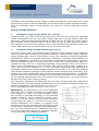
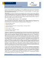
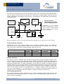
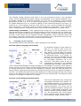
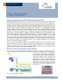
APPLICATION NOTE 208 STM 300 ENERGY STORAGE — Design Considerations Energy management of the STM 300, functioning principle Batteryless EnOcean devices work on the environmental existing energy around them. So the available environmental energy sources are various, for example light, temperature difference and movement, depending on the particular application and its surroundings. If it is to be used, this energy must first be converted into electric charge, for instance by appropriate energy converters like solar cells or Seebeck elements. Typically there is not enough ambient energy continuously available (e.g. nighttime), so rechargeable longterm energy storage is used to ensure functioning when it is dark. The disadvantage is that it needs a relatively long time to reach the startup voltage, and the larger the energy storage capacity the longer the charging time. To support a fast startup and longterm operation in times when no energy supply is available, usually two different kinds of storage are used. The small storage fills quickly and allows fast startup. The large storage fills slowly, but once filled it provides a large buffer for times where no energy is available, e.g. at night (Fig. 1). The STM 300 therefore provides an extra digital output that allows control of the charging of these two external storage mechanisms. The shortterm storage capacitor has a low resistance and also serves as a buffer for the short current spikes (for more details refer to the user manual). The charging voltage can be limited, depending on the storage used, to its nominal operating voltage. So a smaller energy storage capacity can be charged relatively fast, but the stored energy would not suffice to ensure the module surviving over a longer time (e.g. weekend) without energy. On the other hand, through the linear voltage increment on the capacitor under constant charging current, too large a capacity needs too long a time or too large a solar panel to ensure a positive day/night energy balance. Energy converter and energy storage example One of the most common examples of converters of ambient energy is the solar cell. Its efficiency depends on light intensity, the spectral radiation of a light source and its technology (for more details refer to application note AN 207). Depending on application requirements (energy demands and surroundings) different solar cell types and sizes can be chosen. Given that most applications are in homes and buildings, the solar panels used are indoor (typically amorphous) type. One such solar panel consists of a number of serially connected solar cells on the same substrate such as glass (Fig. 2). Fig. 1: Energy storage example © EnOcean | www.enocean.com Fig.2: Solar panel Subject to modifications | Christian Bach | Nov. 2011 | Page 1/ 7 APPLICATION NOTE 208 STM 300 ENERGY STORAGE - Design Considerations Calculation of the delivered electric charge is simple, because for a given light source type the delivered current is directly dependent on the active solar cell area and light intensity, while its (unloaded) output voltage changes very little over a fairly wide light intensity range. Energy storage elements 1. Shortterm energy storage buffer (typ. 470 µF) Unlike the STM 1x0, which needs a split solar panel, the STM 300 already has integrated energy management with only one power supply input and no longer needs a split solar panel. For normal operation and fast startup the STM 300, like the STM 1x0, firstly needs a low resistance, and a capacitor rated a few hundred µF that is called shortterm storage. This capacitor must have a low leakage current, a low resistance and consists typically of a 470 µF SMD (tantalum). So a good solution is the TAJ series from AVX. 2. Longterm energy storage element (typ. 0.25 F) Very much larger (about one thousand times) longterm energy storage covers energy demand over the night or bridges long periods without an external energy supply. Different energy storage types, listed in what follows, can be used, depending on specific application requirements. These are generally Supercaps, Goldcaps or Ultracaps. Recommended for EnOcean applications, depending on functionality (sensor/smart ack/actuator), configuration and available energy (e.g. number and size of solar cells, average ambient light) is a capacitance larger than 0.1 F. Important regarding energy storage is also a very low leakage current (self-discharge) and a sufficiently wide nominal voltage range, ideally up to 5.5 V, since the stored energy is E = ½ C*U2. Generally longterm storage, depending on technology, features low nominal voltages between 2.7 and max. 5.5 V and also relatively high internal resistance. Leakage current depends on the charging time, technology, temperature and rises proportionally with physical dimensions and capacitance. TH (leaded) devices usually have much lower leakage current than SMD alternatives. Their leakage current is typically specified after the first hundred hours charging time. This value tends to fall with time (after some charging weeks). Like electrolytic capacitors, all Supercaps age over time, meaning that their capacitance slowly decreases. The rate of aging depends mainly on the maximum operating voltage and ambient temperature. The last is the key driver; the rate of aging approximately doubles for every +10 °C. Background: The equivalent circuit of such Supercaps looks like many parallel connected RC combinations (see diagram, C = ΣCi). The single resistance values can increase or decrease depending on the individual distance between current collectors, contact resistances, etc. R1, R2 and Rn are the internal resistance of the single cells while C1, C2 and Cn are their electrostatic capacitance. If a voltage V is applied to the equivalent circuit, and considering the equivalent circuit of the electric Supercap as having many small capacitors (Cn) with various internal resistances (Rn), then the current that flows through an individual capacitor Cn can be stated by the following equation: © EnOcean | www.enocean.com Subject to modifications | Christian Bach | Nov. 2011 | Page 2/ 7 APPLICATION NOTE 208 STM 300 ENERGY STORAGE - Design Considerations So the current within the full capacitor can be regarded as the sum Σ of the currents Ii flowing through each of the small capacitors. It can also be seen that if the C x R value is small, the charging time will be short. Conversely, if the time constant C x R value is large, the charging time will be long. Important: It should be noted that if the charging time is limited to only several minutes, or the charging source is current limited, a Supercap may not be sufficiently charged to provide the required backup energy for the intended time. If the capacitor is not sufficiently charged and is called upon to discharge its energy into a load, the discharge current will flow from a high to a low voltage level, thus causing a sharply sinking terminal voltage. A Supercap always requires time to fully charge. 3. Finding the right solution for every application Unlike the shortterm storage buffer, depending on the specific application the most important requirements and priorities for longterm energy storage can be very different. The most common and in part contradictory requirements are listed below: Minimal leakage current Minimal dimensions Lowest possible system price (energy storage + charging circuit) Maximum lifetime Device type TH or SMD Widest possible temperature range Maximum usable energy There is no single best longterm storage device. Every solution has its own advantages and drawbacks. Furthermore, the associated charging circuit is device-specific and can include between one and all of the blocks described below. So every block of the following charging circuits must be individually designed. The block diagram shows the full — maximum — solution where the function of each single block is explained. All the circuits use the STM 300 charge control feature, and all known and applicable energy storage (EDLCs, Electrolytics, PAS capacitors)/accumulators can be charged with at least one of the described charging circuit variants (A, B and C). Due to the low STM 300 quiescent current (compared to the leakage current of the energy storage elements), such energy storage would be completely discharged over longer periods (weeks) in the absence of an energy source. To avoid this, it is recommended that the connection between longterm storage and the STM 300 power input be cut off as soon as the voltage VDD of the STM 300 drops below Voff, as shown in the full charging circuit. Such a procedure also considerably shortens the recovery time after a longer pause (by conserving the residual energy in longterm storage). This application note will give a short overview of the most competitive and appropriate longterm energy storage solutions with their specific charging circuit requirements, and help the user to choose the best solution for their specific application. A very unique and unconventional solution is the use of PAS (polyacenic semiconductor) technology. This combines the properties of a lithium battery (immediately available supply voltage, lowest leakage current with energy conservation over years, smallest dimensions) and a Supercap (very long lifetime, rechargeable) — while it is no battery. The drawback is that such capacitors, unlike all conventional Supercaps, must not be discharged to voltages below about 1.5 V. Otherwise their capacitance decreases over time. So it is essential to observe the manufacturer's handling and soldering instructions. A representative example is the PAS614L capacitor from Taiyo Yuden (Shoei). © EnOcean | www.enocean.com Subject to modifications | Christian Bach | Nov. 2011 | Page 3/ 7 APPLICATION NOTE 208 STM 300 ENERGY STORAGE - Design Considerations Conventional alternatives from ELNA (Dynacap), NEC-Tokin (Supercap) and Kanthal (Maxcap) for specific requirements are listed in the "Alternative energy storage" table at the end of this application note together with their key specifications and associated recommended charging circuits. Charge switcher Overvoltage Energy source protection e.g. solar panel STM 300 Vdd Undervoltage protection VDDLIM WXODIO Depending on the selected longterm storage device, one or more of these function blocks will be needed (circuit variants A/B/C, see below). RC delay C2 C1 Shortterm storage Charge switcher Overvoltage protection Undervoltage protection Longterm storage Block presentation of the universal (fully featured) charging circuit with all its function blocks. Function blocks selection: Depending on the used energy storage device, different charging circuits with different function blocks are recommended. Below are three representative examples (for more details refer to the "Alternative energy storage" table at the end). Energy storage PAS614L FCOV224ZFTBR24 (3.5 V) LT055104A (5.5 V) Charge switcher Yes Yes Yes Overvoltage protection Yes Yes No Undervoltage protection Yes No No Charging circuit A C B Charge switcher: The charge switcher connects both shortterm storage and longterm storage parallel to the energy source as soon as the STM 300 supply voltage reaches the typical Von threshold of 2.45 V. Supposing VDD then falls below Von, the energy source will be switched back to shortterm storage alone, for faster recharging. As long as the voltage on longterm storage remains below Von, the charge switcher will continuously switch the energy source between shortterm and longterm storage, trying to ensure continuous device operation. That is because of the higher resistance and capacitance of longterm storage, which would lead to much too long charging (i.e. non-operative time). In addition shortterm storage cannot be charged over this threshold until the voltage on longterm storage exceeds Von. Overvoltage protection: All of these longterm storage solutions have a rated operating voltage that must be not exceeded. After reaching this limit the energy source is automatically separated from storage to avoid any damage. © EnOcean | www.enocean.com Subject to modifications | Christian Bach | Nov. 2011 | Page 4/ 7 APPLICATION NOTE 208 STM 300 ENERGY STORAGE - Design Considerations Undervoltage protection (deep discharge protection): Some forms of longterm energy storage like rechargeable batteries, but also PAS capacitors, should not be deep discharged. To avoid longterm degradation of their capacity and lifetime, an undervoltage protection block can be added. Transmission of one complete EnOcean telegram requires a known, specific amount of energy. Its consumption causes a voltage drop on the storage element, depending on its capacity. It should be remembered that: E = ½ C*U2 As long as the voltage on shortterm energy storage remains higher than Von, the stored energy is sufficient to transmit at least one complete telegram before the voltage, in the absence of an external energy supply, drops below Voff (refer to the STM 300 user manual). For this purpose a typical 470 µF capacitor value is recommended. That means, as long as shortterm C1 storage is consistently recharged to Von within a predetermined time frame (R6, C3), short voltage undershoots below Von as a result of telegram transmission would cause no separation of longterm C2 storage from a device. Only if the supply voltage still remained below Von after this time frame would a new telegram transmission cause a voltage drop below the Voff threshold. In this case longterm energy storage would be automatically separated from the device to avoid deep discharge. The major advantages of this feature are protection of the PAS capacitor for example, and the shorter recharging time enabled by energy conservation. Circuit A, universal (fully featured), strongly recommended for PAS capacitors: Charge switcher is the PMOS transistor M1, driven from the STM 300 charge control output CCO/WXODIO over Q1. To start with, as long as the Vdd voltage is below the Von threshold, only the small storage C1 is filled over D3. Once the threshold is reached, the charge control signal CCO goes high, Q2 and M2 are turned on and the longterm storage C2 is filled over M2. Overvoltage protection is implemented by the S-1000C32-M5T1x voltage detector from Seiko (SII) or the NCP300LSN30T1G series (Onsemi), which limits the maximum charging voltage to 3.3 V to avoid damaging longterm energy storage. In case a different voltage limit is required, this device has to be replaced by a suitable voltage variant. As soon as the voltage on D2 anode or the voltage detector input exceeds the selected threshold, the voltage detector delivers a High level on its output connected to the Q1 emitter. The Q1 base is consequently lower polarized than its emitter and the transistor is turned off. That means M1 is turned off too — the energy source is switched off and longterm storage is protected. © EnOcean | www.enocean.com Subject to modifications | Christian Bach | Nov. 2011 | Page 5/ 7 APPLICATION NOTE 208 STM 300 ENERGY STORAGE - Design Considerations The selected voltage detector must have a very low quiescent current in the operating range, and an appropriate threshold voltage, corresponding to the selected longterm energy storage voltage (e.g. threshold nominally 3.2 V for a 3.3 V capacitor). If the selected threshold is too low, e.g. 3.0 V, a relatively high amount of energy corresponding to a useful voltage difference of 0.3 V would be wasted. If the nominal threshold is too high, e.g. exactly 3.3 V (not forgetting that this could reach 3.4 V as a result of additional manufacturer tolerances), it could be critical for energy storage life expectation. The S-1000C32M5T1x voltage detector consequently looks like the best compromise here (rated 3.2 V) Undervoltage protection is also implemented through M2. In normal operation, when Vdd reaches the Von threshold, the STM 300 charge control CCO goes high, Q2 rapidly discharges C3 to GND and M2 turns on longterm storage. The C3 charge recovers very slowly over R6, so M2 cannot turn off longterm storage immediately. Only if Vdd falls below Voff for a longer time does C3 have time to recover and finally to turn off M2 and thus the longterm storage path from the STM 300, avoiding deep discharge. 4. Charging circuit variants: The following looks at two alternative “light” charging circuit variants. Circuit B (basic charging circuit alone) If a longterm storage C2 with rated voltage of > 5 V can be used, or the output voltage of the energy source (e.g. solar panel) is limited below C2 nominal voltage, external overvoltage protection as mentioned above is no longer required. In this case the VDDLIM input of the STM 300 connected to VDD is used as overvoltage protection up to 5.5 V/50 mA. This basic circuit B can be consequently sufficient for all standard Supercaps (but not PAS). However, this circuit cannot avoid longterm storage discharge in the absence of energy, which means a longer recovery time for empty energy storage elements. The circuit first charges shortterm C1 storage directly over D3 till the Von threshold is reached. Then the STM 300 starts, its charge control output goes high and M1 switches the energy source to longterm storage C2 over D2. The diodes D2 and D3 avoid self-discharge of energy storage through the energy source in the absence of input energy. D4 ensures a one-way direction of energy flow from longterm C2 storage to shortterm C1 storage. Circuit C (overvoltage protection alone) This circuit implements only charge with overvoltage protection but without undervoltage protection. It is actually the basic circuit above extended with overvoltage protection. The circuit can be used for standard longterm storage not requiring undervoltage protection but having a limited nominal voltage, below 5 V. As mentioned, this circuit cannot avoid longterm deep storage discharging, meaning a longer recovery time. © EnOcean | www.enocean.com Subject to modifications | Christian Bach | Nov. 2011 | Page 6/ 7 APPLICATION NOTE 208 STM 300 ENERGY STORAGE - Design Considerations 5. Alternative energy storages, key specifications and recommended charging circuits (A/B/C) Capacitor Manufacturer Capacitance Temp. range Dimensions (DxH) /F / °C / mm DBS3R6D334T ELNA Dynacap 0.33 -25 to +85 DXS3R6V/H334U ELNA Dynacap 0.33 -25 to +85 DBS3R6D224T ELNA Dynacap 0.22 -25 to +85 DXS3R6V/H224U ELNA Dynacap 0.22 -25 to +85 LT055104A Kanthal Maxcap 0.1 FCOV224ZFT BR24 PAS614LVL3 NEC Tokin Supercap Taiyo Yuden Leakage after first 100 hours charge / nA Voltage max Recommended voltage detector /V Type Max. charge/ discharge current Discharge to 0 V allowed SMD / TH / mA Y/N Estim. dark time operation after 100 h charge up to % (vs PAS) Recommended charge circuit TH 72 Y 170 C 13.5 x 7.5 200 3.6 S-1000C35M5T1G 11.5 x 5.0 11.5 x 13.0 200 3.6 S-1000C35M5T1G TH 72 Y 170 C 13.5 x 7.5 180 3.6 S-1000C35M5T1G TH 66 Y 110 C 11.5 x 5.0 11.5 x 13.0 180 3.6 S-1000C35M5T1G TH 66 Y 110 C -40 to +85 14.5 x 15.5 200 5.5 Not required TH No limits Y 93 B 0.22 -25 to +70 10.5 x 5.5 500 3.5 S-1000C34M5T1G SMD 0.2 Y 70 C 0.25 -20 to +60 6.8 x 1.8 <120* 3.3 (char ged) S-1000C32M5T1G SMD 0.05 N 100 A *Important: The leakage current of PAS614L (lithium technology) drops significantly more with charging time than in all double-layer capacitor technologies (e.g. FC series Supercaps from NEC Tokin), and after a few weeks reaches levels under 60 nA (see diagram). One of the reasons is what is called the longterm forming effect of these capacitors as a result of their inherent construction. PAS capacitors are already charged in manufacture, and they keep their charge even after many months of storage until going into use. Their output voltage characteristic looks rather like that of a rechargeable battery; unlike conventional capacitors, where the output voltage falls linearly with their discharge they maintain the output voltage until near the end of their service life. All other capacitor types are discharged from the beginning, or will be self-discharged within days, and thus are not formed or lose their forming. The longer capacitors are polarized with a sufficiently high voltage, the faster and better is their longterm (weeks) forming process, see also diagrams below. Disclaimer The information provided in this document describes typical features of the EnOcean radio system and should not be misunderstood as specified operating characteristics. No liability is assumed for errors and / or omissions. We reserve the right to make changes without prior notice. For the latest documentation visit the EnOcean website at www.enocean.com © EnOcean | www.enocean.com Subject to modifications | Christian Bach | Nov. 2011 | Page 7/ 7