1
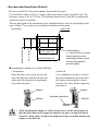
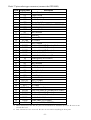
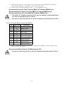
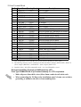
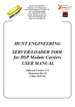
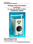
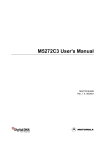
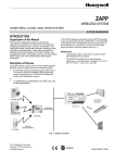
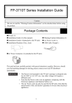
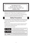
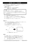
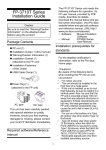
GP2000H Series RS-422 Conversion Adapter (GP2000H-AP422) Installation Guide Thank you for purchasing Pro-face's GP2000H Series RS-422 type Conversion Adapter, hereafter referred to as the "Adapter" Using this adapter allows the user to convert the GP2000H series I/F connector to a terminal block. Please confirm that the following items are all included in the adapter's package. • Installation Guide (This manual) • GP2000H RS-422 type Conversion Adapter Prior to using this adapter, please be sure to read this manual Completely. UL/c-UL(CSA) Approval The GP2000H-AP422 are UL60950 approved product (UL file no. E171486) that can be easily built into your product. When applying for UL approval for a product that includes one of this Adapter, please be sure to pay special attention to the fact that all products with built-in Adapter require UL inspection of the combination of the Adapter and the product. The Adapter components conform to the following standards: UL60950 Third Edition, dated December 1, 2000 (Standard for Safety of Information Technology Equipment, including Electrical Business Equipment) CAN/CSA-C22.2 No. 60950-00 (Standard for Safety of Information Technology Equipment, including Electrical Business Equipment) GP2000H-AP422 (UL Registration Model: 3080028-22) CE Marking The GP2000H-AP422 is CE marked , EMC compliant products. This Adapter also conform to EN55011 Class A, EN61000-6-2 directives. For detailed CE marking information, please contact your local Adapter distributor. -1- <Cable Connection Information> Dsub 37 pin Connector: This connector connects to GP2000H series units. Use the separately sold RS-422 option cable (GP2000H-D422-3M or GP2000H-D422-10M) to connect the two. 10-Line Terminal Block: Connect HOST (Device/PLC) to these terminals. The lines/cable connected here must be created by the User. 22-Line Terminal Block: Connect external output (DOUT, etc.) or power lines to these terminals. The lines/cable connected here must be created by the User. • Prior to attaching the Dsub 37 pin cable to this adapter’s connector, be sure to turn the adapter’s power switch OFF. • Be sure to remove the Conversion adapter from its installation panel when connecting the 10-Line Terminal Block wires or 22-Line Terminal Block wires. This is to prevent possible damage to the Conversion Adapter. • Be sure to always attach the Terminal Block’s transparent plastic cover. Failure to do so could result in an electric shock. <Dimensions> Unit: mm [in.] 128[5.04] 122[4.80] Attachment Clip 10-Line Terminal Block(connect the HOST) 5[0.20] (Transparent plastic cover is attached.) 4-φ4±0.1[4-φ0.16±0.004] 47[1.85] 96[3.78] Power Switch 22-Line Terminal Block Dsub 37 Pin (connect the GP2000H) (Transparent plastic cover is attached.) -2- <Recommended Installation Method> Be sure to install the Conversion adapter from inside the panel. Use stud bolts 14mm [0.55in.] or longer, and secure them in place using M3 nuts. The necessary torque is 0.5 to 0.6 N•m. The drawing shown here is with the recommended connector and cover in place. The size and depth of the attachment screw installation holes will vary depending on the type of Dsub 37 pin connector used and the thickness of the panel. under 4-R3 ] +0.04 0 [1.59 74 +10 [2.91 +0.04 ] 0 +1 0 40.5 38.5±0.2[1.52±0.01] Unit:mm[in.] 88±0.2[3.46±0.01] 4-M3 Stud Bolt L = 14mm [0.55in.] or longer Use enough force when attaching the bolts to cause the rear of the panel to protrude slightly. Attaching the Adapter on a 35mm DIN Rail • Removal Use a standard screwdriver to force the unit's attachment clip down until the bottom of the adapter is freed from the rail. Next, tilt the adapter up and remove. • Attachment Place the unit's curved, top lip over the top of the DIN rail, and then tilt the unit down until the bottom face attachment clip clicks into place. Adapter DIN Rail Adapter Standard Screwdriver DIN Rail Down • When attaching this adapter to a DIN rail, be sure to fix the cable in place so that the cable connected is supported and does not place a weight load on the connector. If the cable’s weight is not supported, it may eventually damage the adapter or the DIN rail. -3- • If wire length is a problem, please use the NC (Not Connected) terminal for connecting the shield (earth) wire, etc. • The recommended length of the wire ends is as shown below. 60mm[2.36in.] • Ring terminal attachment rings should be no more than 0.8mm [0.03in.] thick. If two ring terminals are attached to the same terminal, the combined thickness will be too much and the clear plastic cover cannot be attached. The JST company's V2-MS3 (round type) Ring terminals, or similar types are recommended. • To avoid a short caused by loose ring terminals, be sure to use ring terminals with insulating sleeve. • The necessary torque is 0.5 to 0.6N•m. <Serial Interface> • The connector signals used in this document are based on the use of Pro-face's optional RS-422 cable. (GP2000H-D422-3M or GP2000H-D422-10M) For detailed signal information, please refer to the separately sold GP2000H Series User Manual. • Use rough metric type M2.6 x 0.45p threads to hold the cable's set (fastening) screws in place. -4- Dsub 37 pin socket-type connector (connect the GP2000H) Pin No. Signal Name 1 FG 2 FG 3 NC 4 ERB 5 CSB 6 +5V 7 SDB 8 RDB 9 NC 10 RESERVE 11 12 13 14 15 16 17 18 19 20 21 22 23 24 25 26 27 28 29 30 31 32 33 34 35 36 37 RESERVE OP.GND DOUT.GND EMG0B EMG1B EMG2B ENB0B ENB1B 0V FG NC NC ERA CSA SG SDA RDA DOUT0.C DOUT1.C OP.C BUZZ OUT EMG0A EMG1A EMG2A ENB0A ENB1A +24V Description Frame Ground Frame Ground Not Connected Enable Receive B Clear to Send B DC +5V±5% Output 0.25A (from GP2000H)*1 Send Data B Receive Data B Not Connected Reserved *2 *2 Reserved OP Ground *3 DOUT Ground Push-Lock Switch 0B (Operates like A contact) Push-Lock Switch 1B (B contact) Push-Lock Switch 2B (B contact) Enable Switch 0B (A contact) *4 Enable Switch 1B (A contact) Power Input 0V (to GP2000H) Frame Ground Not Connected Not Connected Enable Receive A Clear to Send A Signal Ground Send Data A Receive Data A DOUT 0 Output DOUT 1 Output OP Output External Buzzer Output Push-Lock Switch 0A (Operates like A contact) Push-Lock Switch 1A (B contact) Push-Lock Switch 2A (B contact) Enable Switch 0A (A contact) *4 Enable Switch 1A (A contact) Power Input +24V (to GP2000H) *1 When connected to the GP, the power used should be a maximum of 0.25A. Be sure to not exceed this level. *2 Pins #10 and #11 are reserved. Be sure to not connect anything to these pins. -5- *3 The DOUT ground is used in common with External Buzzer Output (BUZZ OUT), DOUT 0 (Zero) output (DOUT0.C), and DOUT 1 (One) output (DOUT1.C). *4 Disabled when “GP-H70 compatible mode” (set via GP2000H) is used. Recommended Connector: Dsub 37 pin plug XM2A-3701<made by OMRON Corp.> Recommended Cover: Dsub 37 pin Cover XM2S-3711<made by OMRON Corp.> Recommended Screw: Jack Screw XM2Z-0071<made by OMRON Corp.> • Pin #6 DC+5V Output is not protected. To prevent damage or unit malfunction, use only the designated level of current. • Be sure to connect line #25 (SG) to the SG terminal of your Host (Device/PLC). 10-Line Terminal Block (connect the HOST) Pin No. Signal Name 1 FG 2 SG 3 SDB 4 SDA 5 RDB 6 RDA 7 CSA Description Frame Ground Signal Ground Send Data B Send Data A Receive Data B Receive Data A *1 Clear to Send A *1 8 ERA Enable Receive A 9 CSB Clear to Send B 10 ERB Enable Receive B *1 *1 *1 Wires #7 (CSA) and #8 (ERA), and wires #9 (CSB) and #10 (ERB) are shorted together with shorting clips at the factory. Recommended Ring Terminal: V2-MS3<made by JST> Be sure to connect line #2 (SG) to the SG terminal of your Host (Device/PLC). -6- 22-Line Terminal Block Pin No. Signal Name (Drawing Name) 1 DOUT0.C (DO0) 2 RESERVE 3 DOUT1.C (DO1) 4 RESERVE 5 OP.C (OP) 6 OP.GND (OPG) 7 BUZZ OUT (BZ) 8 DOUT.GND (DOG) 9 EMG0A (EM0A) 10 EMG0B (EM0B) 11 EMG1A (EM1A) 12 EMG1B (EM1B) 13 EMG2A (EM2A) 14 EMG2B (EM2B) 15 ENB0A (EN0A) 16 ENB0B (EN0B) 17 ENB1A (EN1A) 18 19 20 21 22 ENB1B +24V 0V NC FG (EN1B) (+24V) (0V) (NC) (FG) Description DOUT 0 Output *1 Reserved DOUT 1 Output *1 Reserved OP Output OP Ground External Buzzer Output *2 DOUT Ground Push-Lock Switch 0A (Operates like A contact) Push-Lock Switch 0B (Operates like A contact) Push-Lock Switch 1A (B contact) Push-Lock Switch 1B (B contact) Push-Lock Switch 2A (B contact) Push-Lock Switch 2B (B contact) Enable Swith 0A (A contact) Enable Swith 0B (A contact) Enable Swith 1A (A contact) *3 Enable Swith 1B (A contact) Power Input +24V Power Input 0V Not Connected Frame Ground *3 *1 Pins #2 and #4 are reserved. Be sure to not connect anything to these pins. *2 The DOUT ground is used in common with External Buzzer Output (BUZZ OUT), DOUT 0 (Zero) output (DOUT0.C), and DOUT 1 (One) output (DOUT1.C). *3 Disabled when “GP-H70 compatible mode” (set via GP2000H) is used. Recommended Ring Terminal: V2-MS3<made by JST> Fuse Type:FGMB125V2A <Fuji Terminal Industry Co. LTD> equivalent • Make all power lines thick wires (Max.:2mm2) and twist all cable ends. • When connecting the FG line to the installation panel’s frame, use exclusive grounding to minimize the effect of surrounding noise. -7- Note Please be aware that Digital Electronics Corporation shall not be held liable by the user for any damages, losses, or third party claims arising from the uses of this product. Digital Electronics Corporation 8-2-52 Nanko Higashi, Suminoe-ku, Osaka 559-0031, Japan URL: http://www.pro-face.com/ © 2002 Digital Electronics Corporation. All rights reserved. GP2000H-AP422-MT01-CP 2002.7 B -8-