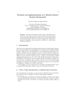
1
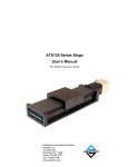
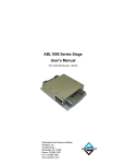
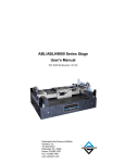
ALAR Series Stage
User’s Manual
P/N: EDS121 (Revision 1.06.00)
Dedicated to the Science of Motion
Aerotech, Inc.
101 Zeta Drive,
Pittsburgh, PA, 15238
Phone: 412-963-7470
Fax: 412-963-7459
www.aerotech.com
Product Registration
Register online at: http://www.aerotech.com/prodreg.cfm
Technical Support
United States Headquarters:
Phone: (412) 967-6440
Fax: (412) 967-6870
Email: [email protected]
United Kingdom:
Phone: +44 118 940 9400
Fax: +44 118 940 9401
Email: [email protected]
Germany:
Phone: +49 911 967 9370
Fax: +49 911 967 93720
Email: [email protected]
Japan:
Phone: +81(0)47-489-1741 (Sales)
Phone: +81(0)47-489-1742 (Service)
Fax: +81(0)47-489-1743
Email: [email protected]
China:
Phone: +852-3793-3488
Email: [email protected]
Revision History
Revision 1.06.00
April 18, 2011
Revision 1.05.00
December 15, 2010
Revision 1.04.00
June 10, 2010
Revision 1.03.00
November 6, 2009
Revision 1.02.00
August 5, 2009
Revision 1.01.00
January 5, 2009
Revision 1.00.00
April 2, 2007
Product names mentioned herein are used for identification purposes only and may be trademarks of
their respective companies.
© Aerotech, Inc. 2011
ALAR Series Stage User's Manual
Table of Contents
Table of Contents
Table of Contents
List of Figures
List of Tables
iii
v
vii
Chapter 1: Overview
1
1.1. Standard Features
1.2. Optional Features
1.2.1. Limited Travel Option
1.2.2. Brake Option
1.2.3. High Torque Option
1.3. Model Numbers and Ordering Options
1.4. Dimensions
1.5. Safety Procedures and Warnings
1.6. EC Declaration of Incorporation
Chapter 2: Installation
2.1. Unpacking and Handling the Stage
2.2. Preparing the Mounting Surface
2.3. Securing the Stage to the Mounting Surface
2.4. Attaching the Payload to the Stage
2.5. Electrical Installation
Chapter 3: Operating Specifications
3.1. Environmental Specifications
3.2. Basic Specifications
3.3. Standard Motor Wiring
3.4. Limit Switch Wiring
3.4.1. Limit Switch Operation (Option)
3.5. Vacuum Operation
Chapter 4: Maintenance
4.1. Service and Inspection Schedule
4.2. Cleaning and Lubrication
4.2.1. Recommended Cleaning Solvents
2
2
2
2
2
3
4
14
16
17
17
18
19
20
21
23
23
24
32
34
34
34
35
35
35
35
Appendix A: Warranty and Field Service
37
Appendix B: Technical Changes
39
Index
41
Reader's Comments
43
www.aerotech.com
iii
Table of Contents
iv
ALAR Series Stage User's Manual
www.aerotech.com
ALAR Series Stage User's Manual
List Of Figures
List of Figures
Figure 1-1:
Figure 1-2:
Figure 1-3:
Figure 1-4:
Figure 1-5:
Figure 1-6:
Figure 1-7:
Figure 1-8:
Figure 1-9:
Figure 1-10:
Figure 1-11:
Figure 2-1:
Figure 2-2:
Figure 2-3:
Figure 3-1:
Figure 3-2:
Figure 3-3:
Standard ALAR Rotary Stages
ALAR-100-LP Dimensions
ALAR-100-SP Dimensions
ALAR-150-LP Dimensions
ALAR-150-SP Dimensions
ALAR-200-LP Dimensions
ALAR-200-SP Dimensions
ALAR-250-LP Dimensions
ALAR-250-SP Dimensions
ALAR-325-LP Dimensions
ALAR-325-SP Dimensions
Results of Flat Versus Non-Flat Mounting
View of an ALAR Stage Showing Mounting Holes
Payload Mounting Holes on ALAR-SP-LT and ALAR-LP-LT Limited Travel Stages
Motor Power Connector
Motor Feedback Connector
Limit Switch Wiring
www.aerotech.com
1
4
5
6
7
8
9
10
11
12
13
18
19
20
32
33
34
v
List of Figures
vi
ALAR Series Stage User's Manual
www.aerotech.com
ALAR Series Stage User's Manual
List of Tables
List of Tables
Table 1-1:
Table 3-1:
Table 3-2:
Table 3-3:
Table 3-4:
Table 3-5:
Table 3-6:
Table 3-7:
Table B-1:
Table B-2:
Model Numbering System
Environmental Specifications
ALAR Series Specifications
Motor Specifications
High Power D-Style Motor Connector Pin Assignment
High Power D-Style Mating Connector
Motor Feedback Connector Pin Assignment (D-Style Connector)
Motor Feedback Connector Mating Connector
Current Changes (1.06.00)
Archived Changes
www.aerotech.com
3
23
24
28
32
32
33
33
39
40
vii
List of Tables
viii
ALAR Series Stage User's Manual
www.aerotech.com
ALAR Series Stage User's Manual
Overview
Chapter 1: Overview
This chapter introduces standard and optional features of the ALAR stages and gives general safety precautions. The ALAR series is available in both continuous and limited travel versions. The apertures in the
series range from 100 mm to 325 mm in diameter.
Figure 1-1:
Standard ALAR Rotary Stages
N O T E : Aerotech continually improves its product offerings, and listed options may be superseded at any
time. Refer to the the Aerotech Motion Control Product Guide for the most current product information at
www.aerotech.com.
www.aerotech.com
Chapter 1
1
Overview
ALAR Series Stage User's Manual
1.1. Standard Features
All ALAR stages incorporate direct drive brushless motors. The maintenance free direct drive and slotless
motor design combine to create outstanding angular positioning and velocity control with exceptionally large
apertures. This is especially useful in scanning applications where torque ripple cannot be tolerated. Other
added benefits of the direct drive are zero backlash and higher speeds.
Every ALAR stage is designed around a set of angular contacts used to maximize performance with respect
to wobble, moment stiffness, and rotating friction. A precision-machined shaft further minimizes wobble. The
design incorporates integral connections that minimize cable issues.
ALAR stage performance is assured with resolutions from 0.02 arc-sec/count to 0.009 arc-sec/count. The
motor and high-performance rotary encoder are directly coupled to a common shaft.
The ALAR comes in two different configurations. The standard profile (SP) unit has high payload capacity
and high moment load stiffness so it can handle applications where its rotation axis is parallel or perpendicular to gravity and the payload center of gravity is cantilevered away from the stage. The low profile
(LP) unit has high payload capacity and is good for applications where the axis of rotation is parallel to gravity. Both the SP and LP units have the same aperture options and motor options. All ALAR stages can handle between 300-1300 lb of axial load.
1.2. Optional Features
1.2.1. Limited Travel Option
The ALAR series of rotary stages are available in limited travel models for light duty applications. These models are offered in total travels of 10° through 340°. Consult factory for standard travel ranges. Limit travels
can also be customized to meet the needs of individual applications. In heavy-duty applications such as
large payloads and/or high torque requirements, custom hardstops are available. Contact the Aerotech factory for your particular requirements.
1.2.2. Brake Option
The ALAR series of rotary stages is available with brakes through custom engineering special order. These
brakes are customer application dependant. Please consult factory for details.
1.2.3. High Torque Option
Two of the large sizes of the ALAR series of rotary stages are available with 50% higher torque for higher performance applications (refer to Table 3-2).
2
Chapter 1
www.aerotech.com
ALAR Series Stage User's Manual
Overview
1.3. Model Numbers and Ordering Options
The stage model number indicates the optional features on a particular stage. To determine the options on
your stage, refer to Table 1-1 for an explanation of the numbering system.
Table 1-1:
Model Numbering System
Stage
ALAR-100-LP
Aperture Diameter
100 mm
Height
65 mm
Options
ALAR-100-LP-LIx
100 mm
75 mm
Limited Travel
ALAR-150-LP
150 mm
65 mm
ALAR-150-LP-LIx
150 mm
75 mm
ALAR-200-LP
200 mm
100 mm
ALAR-200-LP-LIx
200 mm
110 mm
ALAR-250-LP
250 mm
100 mm
ALAR-250-LP-LIx
250 mm
115 mm
ALAR-325-LP
325 mm
100 mm
ALAR-325-LP-LIx
325 mm
115 mm
ALAR-100-SP
100 mm
100 mm
ALAR-100-SP-LIx
100 mm
110 mm
ALAR-150-SP
150 mm
100 mm
ALAR-150-SP-LIx
150 mm
110 mm
ALAR-200-SP
200 mm
150 mm
ALAR-200-SP-LIx
200 mm
160 mm
ALAR-250-SP-2
250 mm
150 mm
ALAR-250-SP-2-LIx
250 mm
165 mm
Limited travel
ALAR-250-SP-3
250 mm
150 mm
Higher Torque
ALAR-250-SP-3-LIx
250 mm
165 mm
Higher Torque, Limited travel
ALAR-325-SP-2
325 mm
150 mm
ALAR-325-SP-2-Llx
325 mm
165 mm
Limited travel
ALAR-325-SP-3
325 mm
150 mm
Higher Torque
ALAR-325-SP-3-Llx
325 mm
165 mm
Higher Torque, Limited travel
www.aerotech.com
Chapter 1
Limited travel
Limited travel
Limited travel
Limited travel
Limited travel
Limited travel
Limited travel
3
Overview
ALAR Series Stage User's Manual
1.4. Dimensions
Figure 1-2:
4
ALAR-100-LP Dimensions
Chapter 1
www.aerotech.com
ALAR Series Stage User's Manual
Figure 1-3:
www.aerotech.com
Overview
ALAR-100-SP Dimensions
Chapter 1
5
Overview
ALAR Series Stage User's Manual
Figure 1-4:
6
ALAR-150-LP Dimensions
Chapter 1
www.aerotech.com
ALAR Series Stage User's Manual
Figure 1-5:
www.aerotech.com
Overview
ALAR-150-SP Dimensions
Chapter 1
7
Overview
ALAR Series Stage User's Manual
Figure 1-6:
8
ALAR-200-LP Dimensions
Chapter 1
www.aerotech.com
ALAR Series Stage User's Manual
Figure 1-7:
www.aerotech.com
Overview
ALAR-200-SP Dimensions
Chapter 1
9
Overview
ALAR Series Stage User's Manual
Figure 1-8:
10
ALAR-250-LP Dimensions
Chapter 1
www.aerotech.com
ALAR Series Stage User's Manual
Figure 1-9:
www.aerotech.com
Overview
ALAR-250-SP Dimensions
Chapter 1
11
Overview
ALAR Series Stage User's Manual
Figure 1-10:
12
ALAR-325-LP Dimensions
Chapter 1
www.aerotech.com
ALAR Series Stage User's Manual
Figure 1-11:
www.aerotech.com
Overview
ALAR-325-SP Dimensions
Chapter 1
13
Overview
ALAR Series Stage User's Manual
1.5. Safety Procedures and Warnings
The following statements apply throughout this manual. Failure to observe these precautions could result in
serious injury to those performing the procedures and damage to the equipment.
This manual and any additional instructions included with the stage should be retained for the lifetime of the
stage.
To minimize the possibility of electrical shock and bodily injury or death, disconnect all electrical power prior to making any electrical connections.
To minimize the possibility of electrical shock and bodily injury or death when any electrical
circuit is in use, ensure that no person comes in contact with the circuitry when the stage is
connected to a power source.
To minimize the possibility of bodily injury or death, disconnect all electrical power prior to
making any mechanical adjustments.
Moving parts of the stage can cause crushing or shearing injuries. All personnel must
remain clear of any moving parts.
Improper use of the stage can cause damage, shock, injury, or death. Read and understand
this manual before operating the stage.
If the stage is used in a manner not specified by the manufacturer, the protection provided
by the stage can be impaired.
Stage cables can pose a tripping hazard. Securely mount and position all stage cables to
avoid potential hazards.
14
Chapter 1
www.aerotech.com
ALAR Series Stage User's Manual
Overview
Do not expose the stage to environments or conditions outside the specified range of operating environments. Operation in conditions other than those specified can cause damage to
the equipment.
The stage must be mounted securely. Improper mounting can result in injury and damage to
the equipment.
Use care when moving the stage. Manually lifting or transporting stages can result in injury.
Only trained personnel should operate, inspect, and maintain the stage.
This stage is intended for light industrial manufacturing or laboratory use. Use of the stage
for unintended applications can result in injury and damage to the equipment.
Before using this stage, perform an operator risk assessment to determine the needed
safety requirements.
www.aerotech.com
Chapter 1
15
Overview
ALAR Series Stage User's Manual
1.6. EC Declaration of Incorporation
Manufactorer:
Aerotech, Inc.
101 Zeta Drive
Pittsburgh, PA 15238
USA
herewith declares that the product:
Aerotech, Inc. ALAR Stage
is intended to be incorporated into machinery to constitute machinery covered by the Directive
2006/42/EC as amended;
does therefore not in every respect comply with the provisions of this directive;
and that the following harmonized European standards have been applied:
EN ISO 12100-1,-2:2003+A1:2009
Safety of machinery - Basic concepts, general principles for design
ISO 14121-1:2007
Safety of machinery - Risk assessment - Par 1: Principles
EN 60204-1:2005
Safety of machinery - Electrical equipment of machines - Part 1: General requirements
and further more declares that
it is not allowed to put the equipment into service until the machinery into which it
is to be incorporated or of which it is to be a component has been found and
declared to be in conformity with the provisions of the Directive 2006/42/EC and
with national implementing legislation, i.e. as a whole, including the equipment
referred to in this Declaration.
Authorized Representative:
Address:
Manfred Besold
AEROTECH GmbH
Süd-West-Park 90
D-90449 Nürnberg
Name:
Position:
Location:
Date:
16
Alex Weibel /
Engineer Verifying Compliance
Pittsburgh, PA
April 18, 2011
Chapter 1
www.aerotech.com
ALAR Series Stage User's Manual
Installation
Chapter 2: Installation
This chapter describes the installation procedure for the ALAR stage, including handling the stage properly,
preparing the mounting surface to accept the stage, securing the stage to the mounting surface, attaching the
payload, and making the electrical connections.
Installation must follow the instructions in this chapter. Failure to follow these instructions
could result in injury and damage to the equipment.
2.1. Unpacking and Handling the Stage
Carefully remove the stage from the protective shipping container. Before operating the stage, it is important
to let the stage stabilize at room temperature for at least 12 hours. It is important to clean the stage by blowing it off with pressurized nitrogen or clean, oil-less air.
Lift the stage by the factory installed eye bolts (if provided, typically on 200, 250, and 325 models). Smaller
stages can be lifted by their sides.
Each stage has a label listing the system part number and serial number. These numbers contain information
necessary for maintaining or updating system hardware and software. Locate this label and record the information for later reference. If any damage has occurred during shipping, report it immediately.
Improper stage handling could adversely affect the stage’s performance. Therefore, use
care when moving the stage. Manually lifting or transporting stages can result in injury.
Lift the stage only by the base. Do not use the tabletop or wiring connections to support the
stage.
www.aerotech.com
Chapter 2
17
Installation
ALAR Series Stage User's Manual
2.2. Preparing the Mounting Surface
The mounting surface should be flat and have adequate stiffness in order to achieve the maximum performance from the ALAR. When an ALAR series stage is mounted to a non-flat surface, the stage can be distorted as the mounting screws are tightened. This distortion will decrease the overall accuracy of the stage.
To maintain accuracy, the mounting surface should be flat within 1 µm per 50 mm.
Adjustments to the mounting surface must be done before the stage is secured. The effects of flatness on
mounting are illustrated in Figure 2-1.
Figure 2-1:
Results of Flat Versus Non-Flat Mounting
N O T E : The stage base is precision machined and verified for flatness prior to stage assembly at the factory. If machining is required to achieve the desired flatness, it should be performed on the mounting surface rather than the stage base. Shimming should be avoided if possible. If shimming is required, it should
be minimized to improve the rigidity of the system.
18
Chapter 2
www.aerotech.com
ALAR Series Stage User's Manual
Installation
2.3. Securing the Stage to the Mounting Surface
ALAR series stages have a fixed mounting pattern available to secure the stage to a mounting surface. Figure 2-2 shows the main mounting holes in the base of the stage. These counter-bored holes are designed for
M6 socket head cap screws for the 150 and smaller models and M8 socket head cap screws for the 200 and
larger models.
The stage must be mounted securely. Improper mounting can result in injury and damage to
the equipment.
Figure 2-2:
www.aerotech.com
View of an ALAR Stage Showing Mounting Holes
Chapter 2
19
Installation
ALAR Series Stage User's Manual
2.4. Attaching the Payload to the Stage
To prevent damage to the stage or parts, test the operation of the stage before any payload is mounted to the
stage tabletop. Proceed with the electrical installation and test the motion control system in accordance with
the system documentation. Document all results for future reference. For information on electrical connections, refer to the Electrical Installation section later in this chapter and the documentation of the motion
control system delivered with the stage.
For all limited travel (-LT) ALAR stages, there are two sets of eight patterned mounting holes. These patterns
are identical but are separated by 14 degrees. Although mounting to either pattern is acceptable, the recommended payload mounting holes depend on whether the stage is a standard profile (-SP) or a low profile (LP) configuration.
The recommended hole pattern for payload mounting in all ALAR-SP-LT stages is indicated with green circles in Figure 2-3. These mounting holes are located nearest to the socket head cap screws (SHCS).
The recommended hole pattern for payload mounting in all ALAR-LP-LT stages is indicated with blue
squares in Figure 2-3. These mounting holes are located about halfway between the socket head cap
screws.
Figure 2-3:
20
Payload Mounting Holes on ALAR-SP-LT and ALAR-LP-LT Limited Travel Stages
Chapter 2
www.aerotech.com
ALAR Series Stage User's Manual
Installation
2.5. Electrical Installation
Aerotech motion control systems are adjusted at the factory for optimum performance. When the ALAR
series stage is part of a complete Aerotech motion control system, setup involves connecting a stage and
motor combination to the appropriate drive chassis with the cables provided. Connect the provided cables to
the motor and feedback connectors on the stage. Labels on the drive indicate the appropriate connections.
Refer to your drive manuals and documentation for additional installation and operation information. In some
cases, if the system is uniquely configured, a drawing showing system interconnects is supplied.
Never connect or disconnect any electrical component or connecting cable while power is
applied, or serious damage can result.
The stage's protective ground is located on pin A4 of the motor connector. If you are using
cables other than those provided by Aerotech, you must connect pin A4 to a ground connection.
N O T E : Refer to controller documentation regarding adjusting servo gains for optimum velocity and position stability.
www.aerotech.com
Chapter 2
21
Installation
22
ALAR Series Stage User's Manual
Chapter 2
www.aerotech.com
ALAR Series Stage User's Manual
Operating Specifications
Chapter 3: Operating Specifications
This chapter contains general technical information about ALAR series stages. Included are basic product
specifications and general information on limit switches and motor wiring.
3.1. Environmental Specifications
The environmental specifications for the ALAR are listed in the following table.
Table 3-1:
Environmental Specifications
Ambient
Temperature
Operating: 10° to 35° C (50° to 95° F)
The optimal operating temperature is 20° C ±2° C (68° F ±4° F). If at any time the operating temperature deviates from 20° C degradation in performance could occur. Contact Aerotech for
information regarding your specific application and environment.
Storage: 0° to 40° C (32° to 104° F) in original shipping packaging
Humidity
Operating: 40 percent to 60 percent RH
The optimal operating humidity is 50 percent RH.
Storage: 30 percent to 60 percent RH, non-condensing in original packaging
Altitude
Operating: 0 to 2,000 m (0 to 6,562 ft) above sea level
Contact Aerotech if your specific application involves use above 2,000 m or below sea level.
Vibration
Use the system in a low vibration environment. Excessive floor or acoustical vibration can affect
stage and system performance. Contact Aerotech for information regarding your specific application.
Dust Exposure
The ALAR stages are not suited for dusty or wet environments. This equates to an ingress protection rating of IP00.
Use
Indoor use only
Do not expose the stage to environments or conditions outside the specified range of operating environments. Operation in conditions other than those specified can cause damage to
the equipment.
www.aerotech.com
Chapter 3
23
Operating Specifications
ALAR Series Stage User's Manual
3.2. Basic Specifications
The ALAR series rotary stage specifications are shown in Table 3-2. Table 3-3 gives standard motor specifications.
Table 3-2:
ALAR Series Specifications
Basic Model
Total Travel
ALAR-100-SP
ALAR-100-LP
ALAR-150-SP
360° Continuous, Limited up to 340°
Aperture Diameter
100 mm (3.94 in)
150 mm (5.91 in)
Length
250 mm (9.84 in)
300 mm (11.81 in)
250 mm (9.84 in)
300 mm (11.81 in)
Width
Height
100 mm (3.94 in)
Mechanical Drive System
Maximum Acceleration
Accuracy
100 mm (3.94 in)
Direct-Drive Brushless Slotless Servomotor
1364 rad/s2
(1)
1009 rad/s2
1330 rad/s2
±18.9 µrad (±3.9 arc-sec)
Repeatability
Maximum Rotary Speed (2)
65 mm (2.56 in)
±2.4 µrad (±0.5 arc-sec)
300 rpm
Resolution
50 rpm
250 rpm
0.1 µrad (0.02 arc sec)
0.08 µrad (0.016 arc
sec)
Maximum Axial Load Capability
1550 N (348 lb)
1175 N (264 lb)
1950 N (438 lb)
Maximum Radial Load Capability
1350 N (303 lb)
950 N (214 lb)
1925 N (433 lb)
250 N-m
150 N-m
450 N-m
Maximum Moment Load Capability
Tilt Error Motion
9.7 µrad
Standard Finish
Black Anodize with Hard-Coated Table Top
Weight
Weight with Limits
Inertia (3)
160 N (36 lb)
81 N (18.1 lb)
182 N (41 lb)
167 N (37.5 lb)
87 N (19.6 lb)
192 N (43.2 lb)
0.022 kg•m2
0.022 kg•m2
0.040 kg•m2
(1) ±18.9 µrad calibrated (HALAR); ±100 µrad uncalibrated.
(2) Maximum speed based on stage capability; maximum application velocity may be limited by system data rate, resolution and bus
voltage.
(3) Unloaded inertia.
24
Chapter 3
www.aerotech.com
ALAR Series Stage User's Manual
Operating Specifications
Table 3-2: ALAR Series Specifications (continued)
Basic Model
Total Travel
Aperture Diameter
ALAR-150-LP
ALAR-200-SP
ALAR-200-LP
360° Continuous, Limited up to 340°
150 mm (5.91 in)
200 mm (7.87 in)
Length
300 mm (11.81 in)
400 mm (15.75 in)
Width
300 mm (11.81 in)
Height
65 mm (2.56 in)
Mechanical Drive System
Maximum Acceleration
Accuracy
100 mm (3.94 in)
Direct-Drive Brushless Slotless Servomotor
829 rad/s2
(1)
361 rad/s2
570 rad/s2
±18.9 µrad (±3.9 arc-sec)
Repeatability
Maximum Rotary Speed (2)
400 mm (15.75 in)
150 mm (5.91 in)
±2.4 µrad (±0.5 arc-sec)
45 rpm
90 rpm
90 rpm
0.09 µrad (0.018 arc
sec)
0.06 µrad (0.012 arc
sec)
0.07 µrad (0.014 arc
sec)
Maximum Axial Load Capability
1325 N (298 lb)
4675 N (1051 lb)
4350 N (978 lb)
Maximum Radial Load Capability
1275 N (287 lb)
4775 N (1073 lb)
4125 N (927 lb)
225 N-m
1600 N-m
1075 N-m
Resolution
Maximum Moment Load Capability
Tilt Error Motion
9.7 µrad
Standard Finish
Black Anodize with Hard-Coated Table Top
Weight
Weight with Limits
Inertia (3)
96 N (21.6 lb)
396 N (89 lb)
277 N (62.3 lb)
106 N (23.8 lb)
423 N (95 lb)
295 N (66.4 lb)
0.031 kg•m2
0.32 kg•m2
0.19 kg•m2
(1) ±18.9 µrad calibrated (HALAR); ±100 µrad uncalibrated.
(2) Maximum speed based on stage capability; maximum application velocity may be limited by system data rate, resolution and bus
voltage.
(3) Unloaded inertia.
www.aerotech.com
Chapter 3
25
Operating Specifications
ALAR Series Stage User's Manual
Table 3-2: ALAR Series Specifications (continued)
Basic Model
Total Travel
ALAR-250-SP-2
ALAR-250-SP-3
ALAR-250-LP
360° Continuous, Limited up to 340°
Aperture Diameter
250 mm (9.84 in)
Length
450 mm (17.72 in)
Width
450 mm (17.72 in)
Height
150 mm (5.91 in)
Mechanical Drive System
Maximum Acceleration
Accuracy
100 mm (3.94 in)
Direct-Drive Brushless Slotless Servomotor
191 rad/s2
287 rad/s2
(1)
407 rad/s2
±18.9 µrad (±3.9 arc-sec)
Repeatability
±2.4 µrad (±0.5 arc-sec)
Maximum Rotary Speed (2)
90 rpm
140 rpm
Resolution
90 rpm
0.05 µrad (0.01 arc sec)
Maximum Axial Load Capability
4950 N (1113 lb)
4950 N (1113 lb)
Maximum Radial Load Capability
5200 N (1169 lb)
5050 N (1135 lb)
1825 N-m
1475 N-m
Maximum Moment Load Capability
Tilt Error Motion
9.7 µrad
Standard Finish
Black Anodize with Hard-Coated Table Top
Weight
503 N (113 lb)
343 N (77.1 lb)
Weight with Limits
534 N (120 lb)
367 N (82.6 lb)
0.50 kg•m2
0.31 kg•m2
Inertia (3)
(1) ±18.9 µrad calibrated (HALAR); ±100 µrad uncalibrated.
(2) Maximum speed based on stage capability; maximum application velocity may be limited by system data rate, resolution and bus
voltage.
(3) Unloaded inertia.
26
Chapter 3
www.aerotech.com
ALAR Series Stage User's Manual
Operating Specifications
Table 3-2: ALAR Series Specifications (continued)
Basic Model
Total Travel
ALAR-325-SP-2
ALAR-325-SP-3
ALAR-325-LP
360° Continuous, Limited up to 340°
Aperture Diameter
325 mm (12.80 in)
Length
525 mm (20.67 in)
Width
525 mm (20.67 in)
Height
150 mm (5.91 in)
Mechanical Drive System
Maximum Acceleration
Accuracy
100 mm (3.94 in)
Direct-Drive Brushless Slotless Servomotor
123 rad/s2
(1)
185 rad/s2
339 rad/s2
±18.9 µrad (±3.9 arc-sec)
Repeatability
±2.4 µrad (±0.5 arc-sec)
Maximum Rotary Speed (2)
120 rpm
150 rpm
Resolution
120 rpm
0.04 µrad (0.009 arc sec)
Maximum Axial Load Capability
5825 N (1310 lb)
5825 N (1310 lb)
Maximum Radial Load Capability
6650 N (1495 lb)
6450 N (1450 lb)
2650 N-m
2200 N-m
Maximum Moment Load Capability
Tilt Error Motion
9.7 µrad
Standard Finish
Black Anodize with Hard-Coated Table Top
Weight
Weight with Limits
600 N(4) (135 lb)
436 N (98 lb)
636 N (143 lb)
489 N (110 lb)
1.0 kg•m2
0.55 kg•m2
Inertia (3)
(1) ±18.9 µrad calibrated (HALAR); ±100 µrad uncalibrated.
(2) Maximum speed based on stage capability; maximum application velocity may be limited by system data rate, resolution and bus
voltage.
(3) Unloaded inertia.
(4) Specified weight is an estimate.
www.aerotech.com
Chapter 3
27
Operating Specifications
Table 3-3:
ALAR Series Stage User's Manual
Motor Specifications
Model
ALAR-100-SP
ALAR-100-LP
ALAR-150-SP
Performance Specifications
Stall Torque, Continuous
N-m
6.0
2.0
10.7
Peak Torque
N-m
24
11.7
42.9
V/krpm
268.7
42.2
209.4
Electrical Specifications
BEMF Constant (line to line, max)
Continuous Current, No Cooling
Peak Current, Stall
A, pk
2.7
5.8
6.2
A, rms
1.9
4.1
4.4
A, pk
10.8
33.5
24.8
A, rms
7.6
23.7
17.5
N-m/A, pk
2.22
0.35
1.73
N-m/A, rms
3.14
0.5
2.45
N-m/√W
0.63
0.16
0.85
Ohms
12.8
4.5
4.3
mH
3.40
0.55
2.15
°C/W
0.82
0.65
0.47
Vdc
340
340
340
Motor Radius
mm
90
90
120
Magnetic Pole Pitch
deg
20
10
14
18
36
26
Force Constant, Sinusoidal Drive
Motor Constant
Resistance, 25 C (line to line)
Inductance (line to line)
Thermal Resistance, No Cooling
Maximum Bus Voltage
Mechanical Specifications
Pole per Rev
28
Chapter 3
www.aerotech.com
ALAR Series Stage User's Manual
Operating Specifications
Table 3-3: Motor Specifications (continued)
Model
ALAR-150-LP
ALAR-200-SP
ALAR-200-LP
Performance Specifications
Stall Torque, Continuous
N-m
2.6
12.9
Peak Torque
N-m
15.4
85.0
V/krpm
58.9
293.9
Electrical Specifications
BEMF Constant (line to line, max)
Continuous Current, No Cooling
Peak Current, Stall
Force Constant, Sinusoidal Drive
Motor Constant
Resistance, 25 C (line to line)
Inductance (line to line)
Thermal Resistance, No Cooling
Maximum Bus Voltage
A, pk
5.4
5.3
A, rms
3.8
3.8
A, pk
31.4
34.8
A, rms
22.2
24.6
N-m/A, pk
0.49
2.44
N-m/A, rms
0.69
3.45
N-m/√W
0.21
0.84
Ohms
5.1
8.0
mH
0.63
6.40
°C/W
0.64
0.42
Vdc
340
340
Mechanical Specifications
Motor Radius
mm
110
150
Magnetic Pole Pitch
deg
8.18
12
44
30
Pole per Rev
www.aerotech.com
Chapter 3
29
Operating Specifications
ALAR Series Stage User's Manual
Table 3-3: Motor Specifications (continued)
Model
ALAR-250-SP-2
ALAR-250-SP-3
ALAR-250-LP
Performance Specifications
Stall Torque, Continuous
N-m
14.1
21.1
15.1
Peak Torque
N-m
92.3
138.5
99.1
V/krpm
319.4
319.4
342.9
Electrical Specifications
BEMF Constant (line to line, max)
Continuous Current, No Cooling
Peak Current, Stall
Force Constant, Sinusoidal Drive
Motor Constant
Resistance, 25 C (line to line)
Inductance (line to line)
Thermal Resistance, No Cooling
Maximum Bus Voltage
A, pk
5.3
8.0
5.3
A, rms
3.8
5.6
3.8
A, pk
34.8
52.2
34.8
A, rms
24.6
36.8
24.6
N-m/A, pk
2.6
2.6
2.8
N-m/A, rms
3.8
3.8
4.0
N-m/√W
0.92
1.12
0.98
Ohms
8.0
5.3
8.0
mH
6.4
4.3
6.4
°C/W
0.42
0.28
0.42
Vdc
340
340
340
Mechanical Specifications
Motor Radius
mm
163
175
Magnetic Pole Pitch
deg
10.59
10
34
36
Pole per Rev
30
Chapter 3
www.aerotech.com
ALAR Series Stage User's Manual
Operating Specifications
Table 3-3: Motor Specifications (continued)
Model
ALAR-325-SP-2
ALAR-325-SP-3
ALAR-325-LP
Performance Specifications
Stall Torque, Continuous
N-m
23.4
35.1
23.4
Peak Torque
N-m
143.3
214.9
143.3
V/krpm
552.8
552.8
552.8
Electrical Specifications
BEMF Constant (line to line, max)
Continuous Current, No Cooling
Peak Current, Stall
Force Constant, Sinusoidal Drive
Motor Constant
Resistance, 25 C (line to line)
Inductance (line to line)
Thermal Resistance, No Cooling
Maximum Bus Voltage
A, pk
5.1
7.6
5.1
A, rms
3.6
5.4
3.6
A, pk
31.2
46.8
31.2
A, rms
22.1
33.1
22.1
N-m/A, pk
4.6
4.6
4.6
N-m/A, rms
6.5
6.5
6.5
N-m/√W
1.4
1.7
1.4
Ohms
10.6
7.1
10.6
mH
8.4
5.6
8.4
°C/W
0.35
0.23
0.35
Vdc
340
340
340
Mechanical Specifications
Motor Radius
mm
211
Magnetic Pole Pitch
deg
8.18
Pole per Rev
www.aerotech.com
44
Chapter 3
31
Operating Specifications
ALAR Series Stage User's Manual
3.3. Standard Motor Wiring
Stages come from the factory completely wired and assembled. For reference, connector pin outputs (pinouts) and general wiring information are given in the following figures. Pinouts are defined in Table 3-4 and
Table 3-6.
N O T E : Refer to the other documentation accompanying your Aerotech equipment. Call your Aerotech representative if there are any questions on system configuration.
N O T E : If you are using your own cables to connect the stage, ensure that motor and ground wires can
handle current higher than the continuous current listed in Table 3-3. The voltage rating of the wire insulation
must be greater than the bus voltage listed in Table 3-3.
Figure 3-1:
Table 3-4:
Motor Power Connector
High Power D-Style Motor Connector Pin Assignment
Pin #
A1
Pin Output
MTR ØA
Description
Motor Phase A
A2
MTR ØB
Motor Phase B
A3
MTR ØC
Motor Phase C
1
MTR SHLD
2
Reserved
Reserved
3
Reserved
Reserved
4
Reserved
Reserved
5
Reserved
Reserved
A4
FRM GND
Ground to stage base
Table 3-5:
Shield for motor wiring connector
High Power D-Style Mating Connector
Backshell
Aerotech P/N
ECK656
3d Party P/N
Amphenol #17-1726-2
Sockets
ECK659
ITT Cannon #DM53744-6
Connector
ECK657
ITT Cannon #DBMM9W4S
32
Chapter 3
www.aerotech.com
ALAR Series Stage User's Manual
Figure 3-2:
Table 3-6:
Pin
#
Operating Specifications
Motor Feedback Connector
Motor Feedback Connector Pin Assignment (D-Style Connector)
1
Pin Output
SIG SHLD
Description
Shield for feedback connector
2
TH+
3
ENC +5V
5
HALL B
Hall Effect B. Brushless motor commutation track output. TTL line driven signal with
rotary motor.
6
MKR-N
Marker N. Incremental encoder output; either the complement of Marker with a line
driven, TTL type encoder or 2.5 V DC bias level with amplified sine wave type encoder.
7
MKR
Marker. Incremental encoder output pulse given once per revolution. Typically used for
home reference cycle.
10
HALL A
Hall Effect A. Brushless motor commutation track output. TTL line driven signal with
rotary motor.
11
HALL C
Hall Effect C. Brushless motor commutation track output. TTL line driven signal with
rotary motor.
12
CW/+ LMT
14
COS
15
COS-N
16
LMT +5V
17
SIN
Positive lead for motor thermistor (to motion controller)
+5 V supply input for optical encoders. Typical requirement is 250 mA.
Clockwise end of travel limit (option)
Cosine. Incremental encoder output; either TTL line driven or amplified sine wave type
signal. COS leads SIN for CW motor rotation.
Incremental encoder output. Complement of cos.
+5 V supply for limit switch
Sine. Incremental encoder output; either TTL line driven or amplified sine wave type signal. COS leads SIN for CW motor rotation.
18
SIN-N
20
LMT COM
Common ground for limit switch
21
ENC COM
+ 5 V return for optical encoders (ground).
24
CW/-LMT
Counterclockwise end of travel limit (option)
Table 3-7:
Incremental encoder output. Complement of sine.
Motor Feedback Connector Mating Connector
Backshell
Aerotech P/N
ECK656
3d Party P/N
Amphenol #17-1726-2
Connector
ECK300
Cinch DB-255
www.aerotech.com
Chapter 3
33
Operating Specifications
ALAR Series Stage User's Manual
3.4. Limit Switch Wiring
N O T E : This section applies only to limited travel models. Continuous travel models do not have this feature.
Hall-effect limit switches are provided with all limited travel ALAR series stages . The limit switch signals
when the stage has reached its maximum useable travel distance in all directions. The limit switch is
mounted to a small circuit board within the stage and two magnets, used as triggers, are mounted to the bottom of the stage table.
If the stage is driven approximately 3° beyond the electrical limit, it will encounter a mechanical stop. Although the operating speed of the stage may be relatively slow, damage to the
stage could result.
3.4.1. Limit Switch Operation (Option)
The limit switch is mounted on a small printed circuit board. ALAR Stages with the limit option include limit
switch wiring integrated into the main wiring connector. Limit switches on ALAR series stages are configured normally-closed. The input to the controller is seen as a logic 0 (typical 0.4V at 12.8 mA) when no
limit condition is present. When the limit switch is activated, a 5V source through a pull-up resistor causes a
logic 1 (typically 4.8-5V) to be seen by the controller input.
Figure 3-3:
Limit Switch Wiring
3.5. Vacuum Operation
Contact the factory for information regarding operation in a vacuum environment.
34
Chapter 3
www.aerotech.com
ALAR Series Stage User's Manual
Maintenance
Chapter 4: Maintenance
The ALAR series stages are designed to be maintenance-free positioning systems.
To minimize the possibility of bodily injury, confirm that all electrical power is disconnected
prior to making any mechanical adjustments.
4.1. Service and Inspection Schedule
It is recommended that the ALAR stage be inspected once per month until a trend develops for the specific
application and environment.
4.2. Cleaning and Lubrication
There are no elements of the ALAR that require added lubrication. The bearings, motors, and encoders for
the ALAR series require no added lubrication or maintenance. Periodic cleaning is recommended.
4.2.1. Recommended Cleaning Solvents
Before using a cleaning solvent on any part of the stage, it is recommended that compressed nitrogen or
clean, dry air be used to blow away small particles and dust. Any metal surface of the stage may be cleaned
with isopropyl alcohol on a lint-free cloth. Avoid getting excess cleaning solvent on the surfaces, as it could
damage the delicate electronics inside.
To minimize the possibility of bodily injury, confirm that all electrical power is disconnected
prior to making any mechanical adjustments.
www.aerotech.com
Chapter 4
35
Maintenance
36
ALAR Series Stage User's Manual
Chapter 4
www.aerotech.com
ALAR Series Stage User's Manual
Warranty and Field Service
Appendix A: Warranty and Field Service
Aerotech, Inc. warrants its products to be free from defects caused by faulty materials or poor workmanship for a minimum period of one year from date of shipment
from Aerotech. Aerotech's liability is limited to replacing, repairing or issuing credit,
at its option, for any products that are returned by the original purchaser during the
warranty period. Aerotech makes no warranty that its products are fit for the use or
purpose to which they may be put by the buyer, where or not such use or purpose
has been disclosed to Aerotech in specifications or drawings previously or subsequently provided, or whether or not Aerotech's products are specifically
designed and/or manufactured for buyer's use or purpose. Aerotech's liability or
any claim for loss or damage arising out of the sale, resale or use of any of its products shall in no event exceed the selling price of the unit.
Aerotech, Inc. warrants its laser products to the original purchaser for a minimum
period of one year from date of shipment. This warranty covers defects in workmanship and material and is voided for all laser power supplies, plasma tubes and
laser systems subject to electrical or physical abuse, tampering (such as opening
the housing or removal of the serial tag) or improper operation as determined by
Aerotech. This warranty is also voided for failure to comply with Aerotech's return
procedures.
Laser Products
Claims for shipment damage (evident or concealed) must be filed with the carrier
Return Procedure
by the buyer. Aerotech must be notified within (30) days of shipment of incorrect
materials. No product may be returned, whether in warranty or out of warranty, without first obtaining approval from Aerotech. No credit will be given nor repairs made
for products returned without such approval. Any returned product(s) must be
accompanied by a return authorization number. The return authorization number
may be obtained by calling an Aerotech service center. Products must be returned,
prepaid, to an Aerotech service center (no C.O.D. or Collect Freight accepted).
The status of any product returned later than (30) days after the issuance of a
return authorization number will be subject to review.
After Aerotech's examination, warranty or out-of-warranty status will be determined. If upon Aerotech's examination a warranted defect exists, then the product(s) will be repaired at no charge and shipped, prepaid, back to the buyer. If the
buyer desires an airfreight return, the product(s) will be shipped collect. Warranty
repairs do not extend the original warranty period.
Returned Product Warranty Determination
After Aerotech's examination, the buyer shall be notified of the repair cost. At such Returned Product
time, the buyer must issue a valid purchase order to cover the cost of the repair and Non-warranty Deterfreight, or authorize the product(s) to be shipped back as is, at the buyer's
mination
expense. Failure to obtain a purchase order number or approval within (30) days of
notification will result in the product(s) being returned as is, at the buyer's expense.
Repair work is warranted for (90) days from date of shipment. Replacement components are warranted for one year from date of shipment.
At times, the buyer may desire to expedite a repair. Regardless of warranty or outof-warranty status, the buyer must issue a valid purchase order to cover the added
rush service cost. Rush service is subject to Aerotech's approval.
www.aerotech.com
Appendix A
Rush Service
37
Warranty and Field Service
ALAR Series Stage User's Manual
On-site Warranty If an Aerotech product cannot be made functional by telephone assistance or by
Repair sending and having the customer install replacement parts, and cannot be returned
to the Aerotech service center for repair, and if Aerotech determines the problem
could be warranty-related, then the following policy applies:
Aerotech will provide an on-site field service representative in a reasonable amount
of time, provided that the customer issues a valid purchase order to Aerotech covering all transportation and subsistence costs. For warranty field repairs, the customer will not be charged for the cost of labor and material. If service is rendered at
times other than normal work periods, then special service rates apply.
If during the on-site repair it is determined the problem is not warranty related, then
the terms and conditions stated in the following "On-Site Non-Warranty Repair"
section apply.
On-site Non-warranty If any Aerotech product cannot be made functional by telephone assistance or purRepair chased replacement parts, and cannot be returned to the Aerotech service center
for repair, then the following field service policy applies:
Aerotech will provide an on-site field service representative in a reasonable amount
of time, provided that the customer issues a valid purchase order to Aerotech covering all transportation and subsistence costs and the prevailing labor cost, including travel time, necessary to complete the repair.
Company Address Aerotech, Inc.
101 Zeta Drive
Pittsburgh, PA
15238-2897
38
Phone: (412) 963-7470
Fax: (412) 963-7459
Appendix A
www.aerotech.com
ALAR Series Stage User's Manual
Technical Changes
Appendix B: Technical Changes
Table B-1:
Current Changes (1.06.00)
Section(s) Affected
Section 3.2.
General Information
Updated motor and stage specifications
www.aerotech.com
Appendix B
39
Technical Changes
Table B-2:
Revision
1.05.00
40
ALAR Series Stage User's Manual
Archived Changes
Section(s) Affected
Section 1.6.
General Information
Added section
1.05.00
Section 3.1.
1.05.00
Chapter 2: Installation,
Section 2.1. , Section 2.3. ,
Section 2.5. , and Section
1.5.
Added section
1.05.00
Section 3.3.
Added note about motor wire current and voltage requirements
1.04.00
Section 2.4.
Added information about payload mounting holes for limited
travel stages
1.03.00
Section 3.2.
Basic Specifications table updated, new Motor Specifications
table added
1.02.00
Section 1.4.
ALAR-325-SP dimensions updated
1.02.00
Section 1.3.
Model Numbering System updated
1.02.00
Section 2.3.
Socket head cap screw specification changed from 6mm to M6
1.02.00
Section 3.2.
Basic Specifications table updated
1.02.00
Section 3.4.
Added clarification on which models contain hall effect limit
switches
1.01.00
Section 1.4.
Dimensions Section added
1.00.00
--
Added safety information and warnings
New Manual
Appendix B
www.aerotech.com
Index
ALAR Series Stage User's Manual
Index
P
Preparing the Mounting Surface
A
Attaching the Payload
18
20
S
C
Cleaning
35
D
Declaration of Incorporation
Dimensions
safety procedures
14
Securing the Stage to the Mounting Surface
19
Specifications
24
Standard Features
2
16
U
4
Unpacking and Handling the Stage
17
E
Electrical Installation
21
Environmental Specifications
23
V
Vacuum Operation
W
L
Lifting the stage
34
17
Warnings
14
Limit Switch
Operation
34
Wiring
34
Limit Switches
34
Lubrication
35
lubrication schedule
35
M
Model numbers
3
model numbers
17
O
Optional Features
2
Brake Option
2
High Torque Option
2
Limited Travel Option
2
Ordering Options
www.aerotech.com
3
Index
41
ALAR Series Stage User's Manual
42
Index
Index
www.aerotech.com
Reader's Comments
ALAR Series Stage Manual
P/N: EDS121, April 18, 2011
Revision 1.06.00
Please answer the questions below and add any suggestions for improving this document.
Is the manual:
Yes
No
Adequate to the subject
Well organized
Clearly presented
Well illustrated
How do you use this document in your job? Does it meet your needs? What improvements, if any, would you
like to see? Please be specific or cite examples.
Stage/Product Details
Name
Model #
Title
Serial #
Company Name
Date Shipped
Address
Customer Order #
Aerotech Subsidiary
Order #
Email
Mail your comments to:
Fax to:
Aerotech, Inc.
101 Zeta Drive
Pittsburgh, PA
15238 U.S.A.
412-967-6870
Email:
[email protected]