1
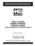
AirLift 115 Series Lift Stage
User’s Manual
P/N: EDS155 (Revision 1.01.00)
Dedicated to the Science of Motion
Aerotech, Inc.
101 Zeta Drive,
Pittsburgh, PA, 15238
Phone: 412-963-7470
Fax: 412-963-7459
www.aerotech.com
Product Registration
Register online at: http://www.aerotech.com/prodreg.cfm
Technical Support
United States Headquarters:
Phone: (412) 967-6440
Fax: (412) 967-6870
Email: [email protected]
United Kingdom:
Phone: +44 118 940 9400
Fax: +44 118 940 9401
Email: [email protected]
Germany:
Phone: +49 911 967 9370
Fax: +49 911 967 93720
Email: [email protected]
Japan:
Phone: +81(0)47-489-1741 (Sales)
Phone: +81(0)47-489-1742 (Service)
Fax: +81(0)47-489-1743
Email: [email protected]
China:
Phone: +852-3793-3488
Email: [email protected]
Revision History
Revision 1.01.00
December 16, 2010
Revision 1.00.00
February 26, 2010
Product names mentioned herein are used for identification purposes only and may be trademarks of
their respective companies.
© Aerotech, Inc. 2010
AirLift 115 Series Stage User's Manual
Table of Contents
Table of Contents
Table of Contents
List of Figures
List of Tables
iii
v
vii
Chapter 1: Overview
1
1.1. Standard Features
1.1.1. Optional Features
1.2. Dimensions
1.3. Safety Procedures and Warnings
1.4. EC Declaration of Incorporation
Chapter 2: Installation
2.1. Unpacking and Handling the Stage
2.2. Air Supply Requirements
2.3. Attaching the Payload to the Stage
2.4. Electrical Installation
2.4.1. End of Travel Limit Switches
2
3
4
6
8
9
9
11
11
12
12
Chapter 3: Operating Specifications
13
3.1. Environmental Specifications
3.2. Accuracy and Temperature Effects
3.3. Basic Specifications
3.4. Limit Switches
3.4.1. Limit Switch Operation
3.4.2. Limit Switch Wiring
3.5. Standard Motor Wiring
3.6. Vacuum Operation
13
13
14
16
16
16
17
19
Chapter 4: Maintenance
4.1. Service and Inspection Schedule
4.2. Cleaning and Lubrication
4.2.1. Recommended Cleaning Solvents
4.2.2. Cleaning Process
4.2.3. Ballscrew Lubrication Procedure
21
21
21
21
22
23
Appendix A: Warranty and Field Service
25
Appendix B: Technical Changes
27
Index
29
Reader's Comments
31
www.aerotech.com
iii
Table of Contents
iv
AirLift 115 Series Stage User's Manual
www.aerotech.com
AirLift 115 Series Stage User's Manual
List Of Figures
List of Figures
Figure 1-1:
Figure 1-2:
Figure 1-3:
Figure 1-4:
Figure 2-1:
Figure 3-1:
Figure 3-2:
Figure 3-3:
Figure 3-4:
Figure 4-1:
Figure 4-2:
Figure 4-3:
Typical AirLift 115 Series Positioning Stage
AirLift 115 Series Stage Components
AirLift 115 Mounting Configuration 1 Dimensions
AirLift 115 Mounting Configuration 2 Dimensions
AirLift 115 With Lifting Hardware and Shipping Brackets Shown
Limit Switch Wiring
Limit and Encoder Wiring for Standard AirLift 115 Stages
Limit Encoder Pin Assignments
Motor Wiring Connector for all AirLift 115 Stages
Air Bearing Surfaces and Encoder Scales Require Periodic Cleaning
Cover Plate Mounting Screw Removal
Grease Fitting and Hard Stop Location
www.aerotech.com
1
2
4
5
10
16
17
18
18
22
23
24
v
List of Figures
vi
AirLift 115 Series Stage User's Manual
www.aerotech.com
AirLift 115 Series Stage User's Manual
List of Tables
List of Tables
Table 1-1:
Table 3-1:
Table 3-2:
Table 3-3:
Table 3-4:
Table B-1:
Table B-2:
Model Numbering System
Environmental Specifications
AirLift 115 Series Specifications
Motor Specifications
Limit/Motor Wiring Pin Descriptions
Current Changes (1.01.00)
Archived Changes
www.aerotech.com
3
13
14
15
19
27
28
vii
List of Tables
viii
AirLift 115 Series Stage User's Manual
www.aerotech.com
AirLift 115 Series Stage User's Manual
Overview
Chapter 1: Overview
This manual describes Aerotech’s AirLift 115 series of air bearing positioning stages. Figure 1-1 shows a typical AirLift 115 positioning stage.
This chapter introduces standard and optional features of the AirLift 115 stages and gives general safety precautions. The AirLift 115 is a single axis air-bearing lift stage, available in travels of 50 mm, 100 mm, and 150
mm.
Figure 1-1:
Typical AirLift 115 Series Positioning Stage
N O T E : Aerotech continually improves its product offerings, and listed options may be superseded at any
time. Refer to the most recent edition of the Aerotech Motion Control Product Guide for the most current
product information at www.aerotech.com.
www.aerotech.com
Chapter 1
1
Overview
AirLift 115 Series Stage User's Manual
1.1. Standard Features
The AirLift 115 series stages offer an ideal solution for applications that require stringent Z direction positioning while maintaining extremely tight angular performance over full travel. Applications include semiconductor wafer inspection and testing, non-contact metrology, optical inspection systems, and laser
processing applications.
The AirLift 115 incorporates air-on-air preload in the lateral directions of motion. The opposing thin-film pressure maintains the bearing nominal gap tolerance. This design, in addition to the large air-bearing surfaces
that distribute the load over a large surface area, results in a stage with outstanding stiffness.
Aerotech's BMS series of brushless rotary motors are included with the AirLift 115 series stages. This motor
has all the advantages of a brushless motor: high acceleration, no brushes to wear, and lower heating, yet it
has zero cogging for extremely smooth motion and accuracy. BMS motors for AirLift 115 are fitted with a failsafe brake, which, coupled with the precision ground ballscrew drive, eliminates the need for the pneumatic
counterbalance typically seen on vertical air bearing stages.
Limit switches and mechanical shock absorbers, which protect the carriage from over travel, are also standard.
Figure 1-2:
2
AirLift 115 Series Stage Components
Chapter 1
www.aerotech.com
AirLift 115 Series Stage User's Manual
Overview
1.1.1. Optional Features
Custom designed AirLift 115 stages can be ordered with features such as higher resolution, custom travel
lengths, and custom mounting options. The standard options for the AirLift 115 are shown in Table 1-1. Contact the Aerotech factory for more details about custom designed stages.
Table 1-1:
Model Numbering System
AirLift 115 Travel Options
AirLift 115050
50 mm travel
AirLift 115100
100 mm travel
AirLift 115150
150 mm travel
Encoder Options
-LTX100
Linear encoder for AirLift 115; 0.05 micron line-driver output
Motor Options
-BMS60-BRK
Brushless servomotor with connectors and brake
-BMS100BRK
Brushless servomotor with connectors and brake
Mounting
-MT1
Mounting configuration 1; mounting surface perpendicular to axis motion
-MT2-050
Mounting configuration 2; mounting surface parallel to axis motion; for 50 mm travel stage
-MT2-100
Mounting configuration 2; mounting surface parallel to axis motion; for 100 mm travel stage
-MT2-150
Mounting configuration 2; mounting surface parallel to axis motion; for 150 mm travel stage
www.aerotech.com
Chapter 1
3
Overview
AirLift 115 Series Stage User's Manual
1.2. Dimensions
Figure 1-3:
4
AirLift 115 Mounting Configuration 1 Dimensions
Chapter 1
www.aerotech.com
AirLift 115 Series Stage User's Manual
Figure 1-4:
www.aerotech.com
Overview
AirLift 115 Mounting Configuration 2 Dimensions
Chapter 1
5
Overview
AirLift 115 Series Stage User's Manual
1.3. Safety Procedures and Warnings
The following statements apply throughout this manual. Failure to observe these precautions could result in
serious injury to those performing the procedures and damage to the equipment.
This manual and any additional instructions included with the stage should be retained for the lifetime of the
stage.
To minimize the possibility of electrical shock and bodily injury or death, disconnect all electrical power prior to making any electrical connections.
To minimize the possibility of electrical shock and bodily injury or death when any electrical
circuit is in use, ensure that no person comes in contact with the circuitry when the stage is
connected to a power source.
To minimize the possibility of bodily injury or death, disconnect all electrical power prior to
making any mechanical adjustments.
Moving parts of the stage can cause crushing or shearing injuries. All personnel must
remain clear of any moving parts.
Improper use of the stage can cause damage, shock, injury, or death. Read and understand
this manual before operating the stage.
If the stage is used in a manner not specified by the manufacturer, the protection provided
by the stage can be impaired.
Stage cables can pose a tripping hazard. Securely mount and position all stage cables to
avoid potential hazards.
6
Chapter 1
www.aerotech.com
AirLift 115 Series Stage User's Manual
Overview
Do not expose the stage to environments or conditions outside the specified range of operating environments. Operation in conditions other than those specified can cause damage to
the equipment.
The stage must be mounted securely. Improper mounting can result in injury and damage to
the equipment.
Use care when moving the stage. Manually lifting or transporting stages can result in injury.
Only trained personnel should operate, inspect, and maintain the stage.
This stage is intended for light industrial manufacturing or laboratory use. Use of the stage
for unintended applications can result in injury and damage to the equipment.
Before using this stage, perform an operator risk assessment to determine the needed
safety requirements.
www.aerotech.com
Chapter 1
7
Overview
AirLift 115 Series Stage User's Manual
1.4. EC Declaration of Incorporation
Manufactorer:
Aerotech, Inc.
101 Zeta Drive
Pittsburgh, PA 15238
USA
herewith declares that the product:
Aerotech, Inc. AirLift 115 Stage
is intended to be incorporated into machinery to constitute machinery covered by the Directive
2006/42/EC as amended;
does therefore not in every respect comply with the provisions of this directive;
and that the following harmonized European standards have been applied:
EN ISO 12100-1,-2:2003+A1:2009
Safety of machinery - Basic concepts, general principles for design
ISO 14121-1:2007
Safety of machinery - Risk assessment - Par 1: Principles
EN 60204-1:2005
Safety of machinery - Electrical equipment of machines - Part 1: General requirements
and further more declares that
it is not allowed to put the equipment into service until the machinery into which it
is to be incorporated or of which it is to be a component has been found and
declared to be in conformity with the provisions of the Directive 2006/42/EC and
with national implementing legislation, i.e. as a whole, including the equipment
referred to in this Declaration.
Authorized Representative:
Address:
Manfred Besold
AEROTECH GmbH
Süd-West-Park 90
D-90449 Nürnberg
Name:
Position:
Location:
Date:
8
Alex Weibel /
Engineer Verifying Compliance
Pittsburgh, PA
December 16, 2010
Chapter 1
www.aerotech.com
AirLift 115 Series Stage User's Manual
Installation
Chapter 2: Installation
This chapter describes the installation procedure of the AirLift 115 stage, including handling the stage properly, the proper base for stage mounting, attaching the payload, and making the electrical and pneumatic connections.
Installation must follow the instructions in this chapter. Failure to follow these instructions
could result in injury and damage to the equipment.
2.1. Unpacking and Handling the Stage
Each stage has a label listing the system part number and serial number. These numbers contain information
necessary for maintaining or updating system hardware and software. Locate this label and record the information for later reference. If any damage has occurred during shipping, report it immediately.
Before operating the stage, it is important to let the stage stabilize to room temperature for at least 12 hours.
Clean the stage by blowing it off with pressurized nitrogen or clean, oil-free air.
Remove all red anodized shipping brackets and lifting hardware before attempting to move the axis (see Figure 2-1).
Improper stage handling could adversely affect the stage’s performance. Therefore, use
care when moving the stage. Manually lifting or transporting the stage can result in injury.
Lift the stage only by the provided lifting hardware.
Do not attempt to move the stage until the air supply, detailed in Section 2.2. , has been
installed. Moving the stage table without air supplied can cause permanent damage to the
stage.
www.aerotech.com
Chapter 2
9
Installation
AirLift 115 Series Stage User's Manual
Figure 2-1:
10
AirLift 115 With Lifting Hardware and Shipping Brackets Shown
Chapter 2
www.aerotech.com
AirLift 115 Series Stage User's Manual
Installation
2.2. Air Supply Requirements
The quality of the air supplied to the air bearing is important for the operation of the system. If compressed air
is used, it must be filtered to 0.25 microns, dry to 0°F dew point, and oil free. If nitrogen is used, it must be
99.99% pure and filtered to 0.25 microns. The filtration requirement is to prevent particles from clogging the
air bearing. Air pressure in the range of 517 kPa to 551 kPa (75 psi to 80 psi) is necessary for use. A standard
airflow rate of 45 to 55 SLPM (standard liters per minute) at 551 kPa should be observed for the entire system.
To protect the air bearing against under pressure or loss of pressure, an inline pressure switch set at no lower
than 40 psi and tied to the motion controller's E-stop is recommended.
2.3. Attaching the Payload to the Stage
To prevent damage to delicate payloads, test the operation of the stage before the payload is attached to the
stage table. Proceed with the electrical installation and test the motion control system in accordance with the
system documentation. Document all results for future reference. For information on electrical connections,
refer to Section 2.4.
The payload should be flat, rigid, and comparable to the stage in quality. For valid accuracies, the mounting
interface should be flat within 1µm per 50mm.
www.aerotech.com
Chapter 2
11
Installation
AirLift 115 Series Stage User's Manual
2.4. Electrical Installation
Electrical installation requirements will vary depending on stage options. Installation instructions in this section are for stages equipped with standard Aerotech motors intended for use with an Aerotech motion control
system. Contact Aerotech for further information regarding stages that are otherwise configured.
Aerotech motion control systems are adjusted at the factory for optimum performance. When the AirLift 115
series stage is part of a complete Aerotech motion control system, setup involves connecting a stage and
motor combination to the appropriate drive chassis with the cables provided. Connect the provided cables to
the motor and feedback connectors on the stage. Labels on the drive indicate the appropriate connections.
Refer to your drive manuals and documentation for additional installation and operation information. In some
cases, if the system is uniquely configured, a drawing showing system interconnects is supplied.
Motor and encoder wiring and connector pin outputs are given in Section 3.5.
Never connect or disconnect any electrical component or connecting cable while power is
applied, or serious damage may result.
The stage's protective ground is located on pin A4 of the motor connector. If you are using
cables other than those provided by Aerotech to connect the motor to the drive, you must
connect pin A4 to a ground connection.
2.4.1. End of Travel Limit Switches
AirLift 115 stages are equipped with a pair of end of travel limit switches. Refer to Section 3.4. for a description of limit switch operation and wiring.
12
Chapter 2
www.aerotech.com
AirLift 115 Series Stage User's Manual
Operating Specifications
Chapter 3: Operating Specifications
This chapter contains general technical information about AirLift 115 series stages. Included are basic product specifications and general information on limit switches and motor wiring.
3.1. Environmental Specifications
The environmental specifications for the AirLift 115 are listed in the following table.
Table 3-1:
Environmental Specifications
Ambient
Temperature
Operating: 10° to 35° C (50° to 95° F)
The optimal operating temperature is 20° C ±2° C (68° F ±4° F). If at any time the operating temperature deviates from 20° C degradation in performance could occur. Contact Aerotech for
information regarding your specific application and environment.
Storage: 0° to 40° C (32° to 104° F) in original shipping packaging
Humidity
Operating: 40 percent to 60 percent RH
The optimal operating humidity is 50 percent RH.
Storage: 30 percent to 60 percent RH, non-condensing in original packaging
Altitude
Operating: 0 to 2,000 m (0 to 6,562 ft) above sea level
Contact Aerotech if your specific application involves use above 2,000 m or below sea level.
Vibration
Use the system in a low vibration environment. Excessive floor or acoustical vibration can affect
stage and system performance. Contact Aerotech for information regarding your specific application.
Dust Exposure
The AirLift 115 stages are not suited for dusty or wet environments. This equates to an ingress
protection rating of IP00.
Use
Indoor use only
Do not expose the stage to environments or conditions outside the specified range of operating environments. Operation in conditions other than those specified can cause damage to
the equipment.
3.2. Accuracy and Temperature Effects
The accuracy of the encoder scale is a key element in the overall positioning accuracy. In most stages, a
scale error can be expected if the temperature of the scale differs from 20° C (68° F); however, the AirLift 115
is designed with encoder scales having vary small coefficients of thermal expansion (CTE). This feature
makes the accuracy of the stage much less dependent on the operating temperature. Although the accuracy
is much less sensitive to temperature than many systems, the best accuracy will still be achieved if the
stage is operated at the 20° C (68° F) temperature at which it was calibrated.
www.aerotech.com
Chapter 3
13
Operating Specifications
AirLift 115 Series Stage User's Manual
3.3. Basic Specifications
Basic AirLift 115 series positioning stage specifications are shown in Table 3-2. For the most recent specifications, see Aerotech's website (www.aerotech.com).
Table 3-2:
AirLift 115 Series Specifications
Mechanical Specifications
Travel
Accuracy(1)
AirLift 115-050
AirLift 115-100
AirLift 115-150
50 mm
100 mm
150 mm
Standard
±2.0 µm
±4.0 µm
±6.0 µm
HALAR
±1.0 µm
±1.25 µm
±1.5 µm
Resolution
0.05 µm
Repeatability (Bidirectional) (1)
±0.5 µm
Straightness(2)
±0.25 µm
±0.35 µm
±0.45 µm
Pitch(2)
±1 arc sec
±1.25 arc sec
±2 arc sec
Roll(2)
±1 arc sec
±1.25 arc sec
±2 arc sec
Yaw(2)
±1 arc sec
±1.25 arc sec
±2 arc sec
Maximum Speed
5 mm/rev
50 mm/s
Maximum Acceleration
Load
Capacity(3)
0.25 g
Vertical
15 kg
Operating Pressure
80 psi
Air Consumption
≤ 40 slpm
Material
Aluminum
MTBF (Mean Time Between Failure)
15,000 Hours
(1) Certified with each stage.
(2) Specifications are for centered load. Other loading configurations will affect specifications.
(3) Axis orientation for on-axis loading is listed.
(4) Specifications are for single-axis systems measured 25 mm above the tabletop. Performance of multi-axis systems is payload
and workpoint dependent. Consult factory for multi-axis or non-standard applications.
(5) To protect air bearing against under-pressure condition, an in-line pressure switch tied to the motion controller is required.
(6) Air supply must be clean, dry to 0°F dew point, and filtered to 0.25 µm or better.
14
Chapter 3
www.aerotech.com
AirLift 115 Series Stage User's Manual
Table 3-3:
Operating Specifications
Motor Specifications
Units
Specifications
Motor Model
BMS60-BRK
BMS100-BRK
-A
-A
N-m (oz-in)
0.33 (46.2)
0.56 (80.0)
Winding Designation
Performance Specifications (1) (5)
Stall Torque, Continuous (2)
Peak Torque
(3)
N-m (oz-in)
1.31 (184.9)
2.26 (320.0)
Rated Speed
rpm
4,000
3,000
Rated Power Output, Continuous
watts
112
133
Voltspk/krpm
19
40
(2)
Amppk
Amprms
2.3
1.6
2.1
1.5
Peak Current, Stall (3)
Amppk
Amprms
9.2
6.5
8.4
5.9
N-m/Amppk
oz-in/Amppk
0.14
20.1
0.27
38.1
N-m/Amprms
oz-in/Amprms
0.20
28.4
0.38
53.9
N-m/√W
oz-in/√W
0.050
7.02
0.076
10.74
Resistance, 25°C (LineLine)
ohms
8.4
12.9
Inductance (Line-Line)
mH
1.30
2.40
Maximum Bus Voltage
VDC
340
340
Thermal Resistance
C/W
1.73
1.35
P
8
8
Electrical Specifications (5)
BEMF Constant (Line-Line,
Max)
Continuous Current, Stall
Torque Constant (4) (8)
Motor Constant (2) (4)
Number of Poles
Mechanical Specifications
Motor Weight
kg (lb)
1.1 (2.4)
1.5 (3.3)
kg-m2
oz-in-s2
1.96x10⁻⁵
0.0028
3.71x10⁻⁵
0.0053
N (lb)
89 (20)
89 (20)
Max Axial Load
N (lb)
89 (20)
89 (20)
Frame Size
NEMA
23
23
Rotor Moment of Inertia
Max Radial Load
(1) Performance is dependent upon heat sink configuration, system cooling conditions, and ambient temperature.
(2) Values shown @ 75°C rise above a 25°C ambient temperature, with housed motor mounted to a 250 mm x 250 mm x 6 mm aluminum heat sink.
(3) Peak torque assumes correct rms current; consult Aerotech.
(4) Torque constant and motor constant specified at stall.
(5) All performance and electrical specifications ±10%.
(6) Maximum winding temperature is 100°C; thermistor trips at 100°C.
(7) Ambient operating temperature range 0°C - 25°C. Consult Aerotech for performance in elevated ambient temperatures.
(8) All Aerotech amplifiers are rated Apk; use torque constant in N-m/Apk when sizing.
www.aerotech.com
Chapter 3
15
Operating Specifications
AirLift 115 Series Stage User's Manual
3.4. Limit Switches
AirLift 115 series stages are provided with end of travel limit switches. The limit switches signal when the
stage has reached its maximum useable travel distance in either direction.
3.4.1. Limit Switch Operation
Limit switches are integral to the stage's linear encoder. They are placed directly on the encoder scale at the
extents of nominal stage travel. When the stage encoder senses a limit, a clockwise (CW) or counterclockwise (CCW) limit signal is generated.
If the stage is driven past the electrical limit, it will encounter the hard stop. The stage's
shocks are designed to the stage's specifications. Damage to the stage could result from a
hard stop strike if the stage is driven at conditions exceeding its maximum velocity, acceleration, or payload specifications.
3.4.2. Limit Switch Wiring
Limit switches are open-collector, TTL–compatible devices powered by 5 Volts that change output states
when the stage approaches its maximum travel distance. Since they are open-collector devices, they may
be interfaced to 24 Volt logic inputs.
With the NC limit configuration, the input to the controller is seen as a logic 0 (typical 0.4V @ 12.8mA) when
no limit condition is present. When the limit switch is activated, a 5V source through a pull-up resistor, on the
controller, causes a logic 1 (typically 4.8-5V) to be seen by the controller input. See Figure 3-1 for a diagram
of limit switch wiring.
Figure 3-1:
16
Limit Switch Wiring
Chapter 3
www.aerotech.com
AirLift 115 Series Stage User's Manual
Operating Specifications
3.5. Standard Motor Wiring
Stages fitted with standard motors and encoders come from the factory completely wired and assembled. For
reference, connector pin outputs and general wiring information are given in the following figures. Pin outputs
are defined in Table 3-4.
N O T E : Refer to the other documentation accompanying your Aerotech equipment. Call your Aerotech representative if there are any questions on system configuration.
N O T E : If you are using your own cables to connect the stage, ensure that motor and ground wires can
handle current higher than the continuous current listed in Table 3-3. The voltage rating of the wire insulation
must be greater than the bus voltage listed in Table 3-3.
Figure 3-2:
www.aerotech.com
Limit and Encoder Wiring for Standard AirLift 115 Stages
Chapter 3
17
Operating Specifications
AirLift 115 Series Stage User's Manual
Figure 3-3:
Figure 3-4:
18
Limit Encoder Pin Assignments
Motor Wiring Connector for all AirLift 115 Stages
Chapter 3
www.aerotech.com
AirLift 115 Series Stage User's Manual
Table 3-4:
Operating Specifications
Limit/Motor Wiring Pin Descriptions
Pin Output
CW Limit
Description
Signal indicating stage maximum travel produced by CW motor rotation (Normally Active
High).
COS
Cosine. Incremental encoder output; either TTL line driven or amplified sine wave type signal. Cos leads Sin for CW/positive motion.
COS-N
Incremental encoder output. Compliment of cos.
Counterclockwise
(CCW/-) Limit
Signal indicating stage maximum travel produced by CCW motor rotation (Normally Active
High).
HOME LMT
Home Limit. Paralleled with CCW/- (with Standard Jumper) or CW/+ (Optional Jumper)
limit. Typically not used.
ENC +5V
+5 V supply input for optical encoders. Typical requirement is 250 mA.
ENC COM
Optical encoder common.
HA
Hall Effect A. Brushless motor commutation track output. TTL line driven signal
HB
Hall Effect B. Brushless motor commutation track output. TTL line driven signal.
HC
Hall Effect C. Brushless motor commutation track output. TTL line driven signal
LMT +5v
+ 5 V supply input for optical limit switch boards. Typical requirement is 50 mA.
LMT COM
Optical limit switch boards common.
MKR
Marker. Incremental encoder output pulse given once per revolution. Typically used for
home reference cycle.
MKR-N
Incremental encoder output; either the compliment of Marker with a line driven, TTL type
encoder or 2.5 VDC bias level with amplified sine wave type encoder.
MTR ØA
Motor Phase A.
MTR ØB
Motor Phase B.
MTR ØC
Motor Phase C.
SIN
Sine. Incremental encoder output; either TTL line driven or amplified sine wave type signal.
Cos leads sin for CW/positive motion.
SIN-N
Incremental encoder output. Compliment of sin.
3.6. Vacuum Operation
The AirLift 115 is an air-bearing stage and is not compatible with operation in a vacuum environment. Contact
Aerotech for alternate solutions.
www.aerotech.com
Chapter 3
19
Operating Specifications
20
AirLift 115 Series Stage User's Manual
Chapter 3
www.aerotech.com
AirLift 115 Series Stage User's Manual
Maintenance
Chapter 4: Maintenance
AirLift 115 stages are designed to be low maintenance systems. The non-contact air bearing surfaces require
no lubrication, and exhibit no wear. However, it is important to clean the bearing surfaces to maintain the
accuracy of the stage. You must lubricate the precision ground ballscrew drive at regular intervals. This chapter will detail the cleaning process and specify recommended cleaning solvents.
N O T E : The bearing area must be kept free of foreign matter and moisture; otherwise, the performance
and life expectancy of the stage will be reduced. See Section 2.2. for air requirements.
To minimize the possibility of bodily injury, confirm that all electrical power is disconnected
prior to making any mechanical adjustments.
4.1. Service and Inspection Schedule
Lubricant inspection and replenishment for AirLift 115 series stages depends on conditions such as duty
cycle, speed, and operating environment. An inspection interval of once per month is recommended until a
trend develops for the application. The grease should be fresh and soft and evenly distributed over the entire
length of the screw shaft. Longer or shorter inspection intervals might be required to maintain a film of lubricant on the ballscrew. If the stage is under a high duty cycle, it might be necessary to lubricate the screw as
often as once per week.
If the application process uses only a small portion of travel for most of the duty cycle, you should periodically
drive the stage through the full travel to redistribute the lubrication along the screw shaft.
The ballscrew support bearings are sealed and should not need lubrication under normal use.
4.2. Cleaning and Lubrication
Only the ballscrew of the AirLift 115 stage requires lubrication. Periodic cleaning to remove dust from the
stage is also recommended.
4.2.1. Recommended Cleaning Solvents
Before using a cleaning solvent on any part of the stage, use Nitrogen, or less preferably, clean, dry compressed air to blow away small particles and dust. For general cleaning and removal of dust, use only isopropyl alcohol on AirLift 115 stages. Do not use acetone on AirLift 115 stages.
Isopropyl alcohol should be conservatively applied to a clean, lint free cloth, and the cloth should be used to
wipe down the stage. Do not use an excessive amount of solvent as it could enter the body of the stage and
potentially damage the air bearing.
The AirLift 115 ballscew drive requires periodic lubrication. THK AFE-CA cleanroom rated grease is applied
to the ballscrew during assembly at Aerotech's factory. For maintenance lubrication, use only THK AFE-CA
grease. Greases of different physical properties cannot be mixed, and doing so could degrade the performance of the stage and eventually cause stage failure.
www.aerotech.com
Chapter 4
21
Maintenance
AirLift 115 Series Stage User's Manual
4.2.2. Cleaning Process
It is recommended that the air bearing surfaces be cleaned often to prevent potential damage to the stage or
decreased performance. Blow the entire stage with Nitrogen or clean, dry, compressed air often to prevent
dust form building up on the stage.
In order to clean the entire length of the air bearing surfaces, it is necessary to move the stage to the positive
travel limit, thereby extending the carriage out of the stage base the maximum amount. Remove any obstructions that could potentially interfere with motion of the carriage, then jog the stage to the positive travel limit.
Once the stage is in position, disable the axis and remove power to the stage. Clean all exposed surfaces as
described in Section 4.2.1. Once the solvent has dried, you can restore power.
Moving the stage table without air supplied can cause permanent damage to the stage.
Refer to Section 2.2. for more information about air requirements and installation.
To minimize the possibility of bodily injury, confirm that all electrical power is disconnected
prior to making any mechanical adjustments.
Figure 4-1:
22
Air Bearing Surfaces and Encoder Scales Require Periodic Cleaning
Chapter 4
www.aerotech.com
AirLift 115 Series Stage User's Manual
Maintenance
4.2.3. Ballscrew Lubrication Procedure
Use the following steps to lubricate the ballscrew. As stated in Section 4.2.1. , use only THK AFE-CA grease
for lubrication.
To minimize the possibility of bodily injury, confirm that all electrical power is disconnected
prior to making any mechanical adjustments.
1. Jog the stage carriage to the negative travel limit and remove power to the stage.
2. Remove the mounting screws to the cover plate on the side of the stage as shown in Figure 4-2 to gain
access to the inside of the stage.
Figure 4-2:
Cover Plate Mounting Screw Removal
3. The ballnut and grease fitting should be visible through the window as shown in Figure 4-3. Engage a
grease gun with appropriate attachment over the ballscrew's grease fitting. AirLift 115 stages use grease
fitting THK# C-MT6x1, and THK's grease gun MG70 with a Type H attachment is recommended.
www.aerotech.com
Chapter 4
23
Maintenance
AirLift 115 Series Stage User's Manual
Figure 4-3:
Grease Fitting and Hard Stop Location
4. Generally, it is recommended that grease be pumped into the ballnut until it just begins to seep out of the
nut and onto the screw shaft. On AirLift 115 stages, this can be difficult to see. Use caution when pumping grease as applying too much can significantly increase the torque required to drive the stage and prevent lubrication from being evenly dispersed along the screw shaft. Remove any clumps of excess
grease and wipe down any surfaces other than the ballscrew that may have come in contact with the
grease.
5. After the ballnut has been properly greased, reinstall the cover plate, and restore power to the stage.
6. Slowly cycle the stage back and forth through travel for a minimum of 10 cycles to distribute the lubrication.
24
Chapter 4
www.aerotech.com
AirLift 115 Series Stage User's Manual
Warranty and Field Service
Appendix A: Warranty and Field Service
Aerotech, Inc. warrants its products to be free from defects caused by faulty materials or poor workmanship for a minimum period of one year from date of shipment
from Aerotech. Aerotech's liability is limited to replacing, repairing or issuing credit,
at its option, for any products that are returned by the original purchaser during the
warranty period. Aerotech makes no warranty that its products are fit for the use or
purpose to which they may be put by the buyer, where or not such use or purpose
has been disclosed to Aerotech in specifications or drawings previously or subsequently provided, or whether or not Aerotech's products are specifically
designed and/or manufactured for buyer's use or purpose. Aerotech's liability or
any claim for loss or damage arising out of the sale, resale or use of any of its products shall in no event exceed the selling price of the unit.
Aerotech, Inc. warrants its laser products to the original purchaser for a minimum
period of one year from date of shipment. This warranty covers defects in workmanship and material and is voided for all laser power supplies, plasma tubes and
laser systems subject to electrical or physical abuse, tampering (such as opening
the housing or removal of the serial tag) or improper operation as determined by
Aerotech. This warranty is also voided for failure to comply with Aerotech's return
procedures.
Laser Products
Claims for shipment damage (evident or concealed) must be filed with the carrier
Return Procedure
by the buyer. Aerotech must be notified within (30) days of shipment of incorrect
materials. No product may be returned, whether in warranty or out of warranty, without first obtaining approval from Aerotech. No credit will be given nor repairs made
for products returned without such approval. Any returned product(s) must be
accompanied by a return authorization number. The return authorization number
may be obtained by calling an Aerotech service center. Products must be returned,
prepaid, to an Aerotech service center (no C.O.D. or Collect Freight accepted).
The status of any product returned later than (30) days after the issuance of a
return authorization number will be subject to review.
After Aerotech's examination, warranty or out-of-warranty status will be determined. If upon Aerotech's examination a warranted defect exists, then the product(s) will be repaired at no charge and shipped, prepaid, back to the buyer. If the
buyer desires an airfreight return, the product(s) will be shipped collect. Warranty
repairs do not extend the original warranty period.
Returned Product Warranty Determination
After Aerotech's examination, the buyer shall be notified of the repair cost. At such Returned Product
time, the buyer must issue a valid purchase order to cover the cost of the repair and Non-warranty Deterfreight, or authorize the product(s) to be shipped back as is, at the buyer's
mination
expense. Failure to obtain a purchase order number or approval within (30) days of
notification will result in the product(s) being returned as is, at the buyer's expense.
Repair work is warranted for (90) days from date of shipment. Replacement components are warranted for one year from date of shipment.
At times, the buyer may desire to expedite a repair. Regardless of warranty or outof-warranty status, the buyer must issue a valid purchase order to cover the added
rush service cost. Rush service is subject to Aerotech's approval.
www.aerotech.com
Appendix A
Rush Service
25
Warranty and Field Service
AirLift 115 Series Stage User's Manual
On-site Warranty If an Aerotech product cannot be made functional by telephone assistance or by
Repair sending and having the customer install replacement parts, and cannot be returned
to the Aerotech service center for repair, and if Aerotech determines the problem
could be warranty-related, then the following policy applies:
Aerotech will provide an on-site field service representative in a reasonable amount
of time, provided that the customer issues a valid purchase order to Aerotech covering all transportation and subsistence costs. For warranty field repairs, the customer will not be charged for the cost of labor and material. If service is rendered at
times other than normal work periods, then special service rates apply.
If during the on-site repair it is determined the problem is not warranty related, then
the terms and conditions stated in the following "On-Site Non-Warranty Repair"
section apply.
On-site Non-warranty If any Aerotech product cannot be made functional by telephone assistance or purRepair chased replacement parts, and cannot be returned to the Aerotech service center
for repair, then the following field service policy applies:
Aerotech will provide an on-site field service representative in a reasonable amount
of time, provided that the customer issues a valid purchase order to Aerotech covering all transportation and subsistence costs and the prevailing labor cost, including travel time, necessary to complete the repair.
Company Address Aerotech, Inc.
101 Zeta Drive
Pittsburgh, PA
15238-2897
26
Phone: (412) 963-7470
Fax: (412) 963-7459
Appendix A
www.aerotech.com
AirLift 115 Series Stage User's Manual
Technical Changes
Appendix B: Technical Changes
Table B-1:
Current Changes (1.01.00)
Section(s) Affected
Section 1.4.
Section 3.1.
Chapter 2: Installation, Section 2.1. , Section 2.4. , and Section 1.3.
Section 3.5.
www.aerotech.com
General Information
Section added
Section added
Safety information and warnings added
Note about motor wire current and voltage requirements added
Appendix B
27
Technical Changes
Table B-2:
Revision
1.00.00
28
AirLift 115 Series Stage User's Manual
Archived Changes
Section(s) Affected
--
General Information
New manual
Appendix B
www.aerotech.com
Index
AirLift 115 Series Stage User's Manual
Index
Specifications
14
Standard Features
A
2
Standard Motor Wiring
Air Supply Requirements
11
Attaching the Payload
11
17
U
Unpacking and Handling the Stage
9
B
Ballscrew Lubrication
W
23
Warnings
6
C
12
cables
Cleaning
21-22
Cleaning Solvents
21
D
Declaration of Incorporation
8
E
Electrical Installation
12
encoders
17
Environmental Specifications
13
I
Inspection Schedule
21
L
Limit Switches
16
Lubrication
21
M
model numbers
9
O
Optional Features
3
S
safety procedures
www.aerotech.com
6
Index
29
AirLift 115 Series Stage User's Manual
30
Index
Index
www.aerotech.com
Reader's Comments
AirLift 115 Series Stage Manual
P/N: EDS155, December 16, 2010
Revision 1.01.00
Please answer the questions below and add any suggestions for improving this document.
Is the manual:
Yes
No
Adequate to the subject
Well organized
Clearly presented
Well illustrated
How do you use this document in your job? Does it meet your needs? What improvements, if any, would you
like to see? Please be specific or cite examples.
Stage/Product Details
Name
Model #
Title
Serial #
Company Name
Date Shipped
Address
Customer Order #
Aerotech Subsidiary
Order #
Email
Mail your comments to:
Fax to:
Aerotech, Inc.
101 Zeta Drive
Pittsburgh, PA
15238 U.S.A.
412-967-6870
Email:
[email protected]