1
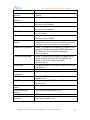
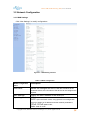
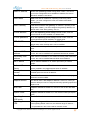
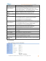
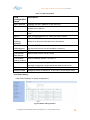
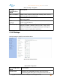
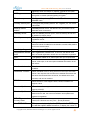
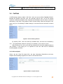
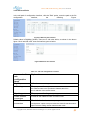
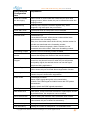
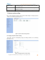
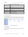
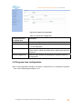
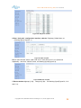
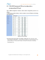
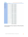
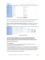
UTT-110B VOIP Gateway (SIP) User manual
UTT-110B Series VOIP Gateway
(SIP)
User manual
VER 1.0
Copyright©2013, Shenzhen Ultrative Technologies Co., Ltd All rights reserved
1
UTT-110B VOIP Gateway (SIP) User manual
Copyright
This manual refers to the sole ownership by the Shenzhen Ultrative Technology Co., Ltd.
(hereinafter referred to as Ultrative) exclusive ownership without the written permission of the
Company, any unit or individual is not entitled to any form of copy, disseminate and
reproduction in part or all of the contents of this manual, Ultrative reserves the right to charge
against law.
Note: This manual is for the user of UTT-110B Series VOIP gateways; the company has
the final interpretation of the manual and might improve, at any time, the products mentioned
and the manual itself without prior noticing.
This document contains proprietary intellectual property rights owned by Shenzhen
Ultrative Technology Co., Ltd, all rights reserved.
Unless mentioned elsewhere, Shenzhen Ultrative Technology Co., Ltd., is the only
registered trademark in China and worldwide. For more information, please contact us
directly
Windows 98/NT/2000/XP/2003/7 Windows operating systems mentioned in this manual, its
trademarks and products are copyright owned by Microsoft Corporation.
Company: Shenzhen Ultrative Technologies Co.,Ltd.
Address: 011#, 6/F, Block A, Hedong Bldg., Liutang Rd.,
Xixiang St., Bao An District, 518102, Shenzhen, China
Hotline: +86(755) 29630367
Postcode: 518102
Webpae: http://www.Ultrative.com.cn
Email : [email protected]
Copyright©2013, Shenzhen Ultrative Technologies Co., Ltd All rights reserved
2
UTT-110B VOIP Gateway (SIP) User manual
INDEX
UTT-110B SERIES VOIP GATEWAY (SIP) ...................................................................... 1
COPYRIGHT..................................................................................................................... 2
PART I
MANUAL GUIDANCE ....................................................................................... 5
1.1 PURPOSE ........................................................................................................................ 5
1.2 TARGET READERS............................................................................................................ 5
1.3 ABOUT THE CONTENT ....................................................................................................... 5
1.4 REMARKS ........................................................................................................................ 5
PART II PRODUCT INTRODUCTION .............................................................................. 6
2.1 CHARACTERISTICS OF UTT-110B SERIES VOIP GATEWAY ................................................ 6
2.2 UTT-110B SERIES SPECIFICATIONS ................................................................................. 8
2.3 UTT-110B MODEL NAME ................................................................................................. 8
2.4 PACKAGING ..................................................................................................................... 8
2.5 APPEARANCE................................................................................................................... 9
2.5.1 Products Panel Diagram ......................................................................................... 9
2.5.2 LED Indicators ........................................................................................................ 9
2.6 HARDWARE CONNECTION............................................................................................... 10
2.6.1 Connection to LAN by Static IP or DHCP.............................................................. 10
2.6.2 As a proxy server is responsible for dial-up Internet ............................................. 10
2.7 NETWORK ACCESS CONFIGURATION ............................................................................... 11
2.8 LOG-IN TO THE WEB CONFIGURATION INTERFACE ........................................................... 11
PART III BASIC WEB SETTINGS .................................................................................. 14
3.1 SYSTEM MANAGEMENT .................................................................................................. 14
3.2 NETWORK CONFIGURATION ............................................................................................ 16
3.2.1 WAN Settings ........................................................................................................ 16
3.2.2 LAN Setting ........................................................................................................... 18
3.2.3 Route Setting ........................................................................................................ 19
3.3 SIP SETTINGS ............................................................................................................... 20
3.4 CALLPATH ................................................................................................................... 22
3.4.1 Add a call path ...................................................................................................... 22
3.4.2 Add a call Rule ...................................................................................................... 23
3.5 PORT SETTINGS ............................................................................................................ 24
3.5.1 Port Basic Settings ................................................................................................ 25
3.5.2 Advance Settings .................................................................................................. 26
3.6 PHONE NUMBER SETTING................................................................................................ 28
3.6.1 Single port phone number setting ......................................................................... 28
3.6.2 Port bulk configuration .......................................................................................... 29
3.7 SYSTEM TOOL ................................................................................................................ 29
3.8 PROGRESS TONE CONFIGURATION .................................................................................. 30
3.9 SYSTEM STATUS ............................................................................................................ 31
Copyright©2013, Shenzhen Ultrative Technologies Co., Ltd All rights reserved
3
UTT-110B VOIP Gateway (SIP) User manual
PART 4
IVR INQUIRY AND IP ADDRESS CONFIGURATION .................................... 32
4.1 WAN PORT IP INQUIRY AND CONFIGURATION ................................................................... 32
4.2 LAN PORT IP INQUIRY AND CONFIGURATION .................................................................... 33
4.3 INQUIRY PHONE NUMBER OF THE PORT ............................................................................ 33
PART FIVE TYPICAL APPLICATION CONFIGURATION(16FXS+16FXO) ................... 33
5.1 CONFIGURATION OF FXS+FXO PORT EQUIPMENT FOR DIAL “9” IN SECONDARY DIAL .......... 33
5.2 FXS+FXO EQUIPMENT FXO PORT CONFIGURATION— CORRESPONDING FXS PORT ....... 38
Copyright©2013, Shenzhen Ultrative Technologies Co., Ltd All rights reserved
4
UTT-110B VOIP Gateway (SIP) User manual
Part I
Manual Guidance
1.1 Purpose
In order to help users of our devices to understand and use our UTT-110B Series
GWs more effectively, hereby, we present this User Manual with our sincerity. This Manual
consists of all detailed information that one need to know about the products.
1.2 Target Readers
The target readers of this manual includes:
I.T. Engineer
Sales Engineer
NOC
1.3 About the content
UTT-110BSeries VOIP Gateway (SIP) User manual offers detailed hardware
specifications, installations, allocation and LED indication, together with elaborate WEB
configuration demonstration.
This manual has the following:
Part
I: Manual Guidance
Part II: Product Introduction
Part III: Basic WEB Settings
Part IV: IVR Inquiry, IP address setting.
Part
V: Typical Scenario
1.4 Remarks
All the following Examples are based on UTT-7500-16FXS16FXO as the only subject.
Copyright©2013, Shenzhen Ultrative Technologies Co., Ltd All rights reserved
5
UTT-110B VOIP Gateway (SIP) User manual
Part II Product Introduction
UTT-110B Series VOIP Gateway gives way to standard IP Audio/Fax/Data services,
which is also called Integrated Access Device or Access Gateway. Normally, in a NGN,
UTT-110B belongs to the Access Layer of the network. Its main role is to combine all
network terminals into a unified web, in order to make all services possible in the network.
By adhering all traditional circuit exchange features, UTT-110B further delivers
advantages that IP technology can bring, making smooth migration from traditional PSTN
to NGN possible; At the meantime, UTT-110B can deliver value-add services just within
the traditional PSTN network, providing a more flexible and balanced choice for
customers. This series—UTT-110B VoIP Gateways, supports 1-2 channels of VoIP
communications, has been widely used in Government Agencies, Commercial
Organizations and Large Corporate for their own communication network. It is an ideal
product to be used in where VoIP communication is required.
2.1 Characteristics of UTT-110B Series VOIP Gateway
Carrier-class reliability
Support Efforts to improve fault detection, network alarm functions.
Low Power Consumption and High Density integration.
Supports 3rd Level lightning protection
POTS Interfaces support over-current protection.
Using ripple smaller, higher-quality communication power, support surges,
power lines and other protective lap, output stability, high reliability, and
supports instantaneous power protection.
Using electromagnetic radiation shielding properties of the chassis,
electromagnetic compatibility, ROHS and so do the professional design, can
effectively shield electromagnetic interference variety of environments.
Transmission loss, loss frequency, nonlinear distortion, crosstalk attenuation,
noise, and non-cross-cross heavy heavy noise and other indicators have
reached the telecommunicationsstandard.
Flexible, powerful security policy
Support administrator login and password protection, built-in firewall function,
can effectively prevent the various network virus attacks, and improve data
security.
Multiple protocol support capabilities
Support the SIP protocol.
Copyright©2013, Shenzhen Ultrative Technologies Co., Ltd All rights reserved
6
UTT-110B VOIP Gateway (SIP) User manual
Support SNMP network management protocol, centralized network
management devices, remote monitoring and maintenance.
Support T.30, T.38 voice pass-through protocol, fax service on IP bearer
network.
Support RTP / RTCP protocol, to achieve real-time voice packet encapsulation
and voice playback.
Audio Services support capabilities
Support for voice, fax, Modem services.
Support a variety of basic voice services and value-added services.
IP telephony and traditional PSTN phone switch.
Flexible access
Support IP line access.
Support xDSL dial-up access.
Support Cable Modem access.
Diversity management
Support for SNMP-based remote centralized network management device.
Web-based network management support equipment.
Powerful QoS guarantee
Based on IPv4 Tos and DiffServ support services to ensure the voice priority.
Support IEEE802.1P, IEEE802.1Q.
Multi-adjustable parameters
Including the supply voltage can be adjusted, the loop current, ringing voltage,
long-term, short-term, impedance parameters and so on.
Advanced voice processing technology
Support ITU-T G.711a/mu, G.729, G.723.1, and other speech coding.
Support voice activity detection (VAD), effectively save network bandwidth
resources.
Support Comfort Noise Generation (CNG).
Support echo cancellation, up to 64ms.
Supports adaptive dynamic buffering technique.
Supports packet loss compensation.
Support DTMF generation / detection.
Support Caller ID detection and display functions.
Support DTMF band, SIPINFO, RFC2833 transmission technology.
Support flexible input / output gain control.
Copyright©2013, Shenzhen Ultrative Technologies Co., Ltd All rights reserved
7
UTT-110B VOIP Gateway (SIP) User manual
1:1 Lifeline function supported.
Support one phone dual-number function
2.2 UTT-110B Series Specifications
Graph 2-1
UTT-110B Series Specifications
Project
UTT-110B Series
Adaptor (Input /
Output)
Input: 100-240V Output: 12V 1A
Interface (WAN)
10/100Base- T RJ-45 for LAN, Auto MDIX
Interface (LAN)
10/100Base- T RJ-45 for PC, Auto MDIX
Power Consumption
Idle: 4 W / full load: 6W
Operating
Temperature
-5 ~ 50 ℃
Relative Humidity
5 ~ 95% non-condensing
The main chip
5VT-1310
DSP
5VT-1310
CODEC
ZL88601
Flash
32 MB
SDRAM
256MB
Dimensions (Lx H x
W)
116mm × 91mm × 30mm
Weight
140g
2.3 UTT-110B Model Name
Graph 2-2 UTT-110B Model Name
Product Name
FXS
FXO
UTT-110B-1FXS
1
0
UTT-110B-2FXS
2
0
UTT-110B-1FXS1FXO
1
1
2.4 Packaging
Before installing, make sure that the product packing list:
UTT-110B Gateway *1
Power Cord *1
Product Manuals CD * 1
Product warranty card *1
Copyright©2013, Shenzhen Ultrative Technologies Co., Ltd All rights reserved
8
UTT-110B VOIP Gateway (SIP) User manual
Network cable *1
Telephone lines * 1-2
2.5 Appearance
2.5.1 Products Panel Diagram
Image 2-1 Front Panel
Image 2-2 Rear Panel
2.5.2 LED Indicators
Table 2-2 Front panel connectors and LEDs
Front panel
connectors
and LEDs
Alarm
Active
Power
1-2
Description
Alarm LED, all the ports open registration, while not registered
as a flashing softswitch, softswitch registration Alarm goes off.
Status indicators, the normal operation of the lamp is flashing.
Power indicator, turn the lights connected to the
power supply for the long bright state.
Port work light, off-hook, ringing, the lights are flashing during
a call, the standby is off.
Table 2-3 Rear panel connectors and LEDs
The rear panel
connectors and
LEDs
ON / OFF
AC 100-240V
Description
Power switch, ON / Off
Power cord interface, connect the power cord.
Equipment upstream interface, when in the 10M Ethernet port
WAN
rate, the green light, orange light off; When working in the 100M
Ethernet port speed, green and orange lights are on, when the flow
of data out of date, the green light, orange lights flashing.
Device configuration interface, when in the 10M Ethernet port
LAN
rate, the green light, orange light off; When working in the 100M
Ethernet port speed, green and orange lights are on, when the flow
Copyright©2013, Shenzhen Ultrative Technologies Co., Ltd All rights reserved
9
UTT-110B VOIP Gateway (SIP) User manual
of data out of date, the green light, orange lights flashing.
1
FXS connected to a telephone or PBX trunk interfaces
2
FXO interfaces connected to the PSTN or PBX extension
2.6 Hardware Connection
2.6.1 Connection to LAN by Static IP or DHCP
1) applies has internal LAN or home users.
2) WAN port UTT-110B Series integrated access devices connected to the hub or switch,
as shown in Figure 2-3.
3) WAN port based on the local area network environment, using PPPoE dial-up mode,
dynamically obtain IP (DHCP) or static IP mode.
Figure 2-3 Series integrated access devices in the LAN connection
2.6.2 As a proxy server is responsible for dial-up Internet
1) UTT-110B Series Voice over IP Integrated Access Device Modem WAN port directly
connected with ADSL (Cable), as shown in Figure 2-4.
2) UTT-110B Series Voice over IP Integrated Access Device as a proxy server, agent in
charge of the Internet.
Copyright©2013, Shenzhen Ultrative Technologies Co., Ltd All rights reserved
10
UTT-110B VOIP Gateway (SIP) User manual
Figure 2-4
UTT-110B Series Integrated Access Device as a proxy server connection
2.7 Network Access Configuration
Firstly confirm the connection: WAN port UTT-110B Series integrated access devices
support PPPoE, dynamic IP address or a static IP address mode
2.8 Log-in to the WEB Configuration Interface
1) selection has a computer card and TCP / IP protocol installed, the
computer and UTT-110B Series Voice over IP integrated access device's LAN
port to connect to a hub or switch with a network cable, network cable can also
be used to connect directly to the computer and the LAN port.
2) Turn on the computer "My Network Places" and "local connection", right
click and choose Properties. Below, the IP address of the computer with
UTT-110B Series Voice over IP integrated access device's LAN port IP
address is configured on the same network segment. (UTT-110B Series The
factory default LAN port IP voice integrated access device is IP
is192.168.11.1, subnet mask is 255.255.255.0.)
Copyright©2013, Shenzhen Ultrative Technologies Co., Ltd All rights reserved
11
UTT-110B VOIP Gateway (SIP) User manual
Figure2-5
PC Ipaddress Setting
Ping command to test whether and UTT-110B Series IP voice
integrated access devices connected properly.
C: \> ping 192.168.11.1
Pinging 192.168.11.1 with 32 bytes of data:
Reply from 192.168.11.1: bytes = 32 time <1ms TTL = 255
Reply from 192.168.11.1: bytes = 32 time <1ms TTL = 255
If the above prompt appears, indicating that the computer has access to
the normal communication can be integrated Voice over IP devices and
UTT-110B the series.
C: \> ping 192.168.11.1
Pinging 192.168.11.1 with 32 bytes of data:
Request timed out.
Request timed out.
If the above message appears, it means that the computer and the UTT
Series Voice over IP integrated access devices connected nowhere please
first check your UTT-110B Series Voice over IP integrated access device is
connected properly (under normal circumstances, AN port status LEDs are
point bright), and then enter the "Internet Protocol (TCP / IP) Properties" page
to see if your computer's IP address is configured correctly.
3 ) Click
,input at the address bar http://192.168.11.1 (LAN Default IP:
192.168.11.1), then:
Copyright©2013, Shenzhen Ultrative Technologies Co., Ltd All rights reserved
12
UTT-110B VOIP Gateway (SIP) User manual
Figure2-6
WEB Login Interface
User Name:admin,Password: admin, ( Default Username: admin passowrd:
admin),Click Enter then,
Figure 2-4
WEB Setting interface
Copyright©2013, Shenzhen Ultrative Technologies Co., Ltd All rights reserved
13
UTT-110B VOIP Gateway (SIP) User manual
Part III Basic WEB Settings
3.1 System Management
Login Succeeded, then go to System Management
Figure3-1
System Management Interface
Graph 3-1 System Management
System Management
Configuration Item
System upstream
agreement
RFC2833 payload
type
Descriptions
Default device using SIP protocol dropdown MGCP/H248
temporarily not take effect.
With DTMF mode "rfc2833" use. Default value 101, a
limited range of values from 97 to 101. Default, the
parameters to be consistent with the peer device, but it can
also auto-negotiation.
RTP start port
Min sending and receiving RTP port, this parameter
can not be less than 3000, it is recommended to configure
the default value can not be less than 10,000, and can be
modified.
RTP port step
RTP step parameter settings, the default port 10, the
drop-down can be modified.
WEB port
Telnet port
Log WEB configuration interface of the
portfacilities, with a default value of 80, can be modified.
telnet port used to configure the device, the default
Copyright©2013, Shenzhen Ultrative Technologies Co., Ltd All rights reserved
14
UTT-110B VOIP Gateway (SIP) User manual
23, can be modified.
Hook without dialing
timeout
Between dialing
timeout
Ringing Timeout
The default value is 16s, the drop-down can be
modified.
The default value 4s, drop-down can be modified.
Telephone ringing timeout, the default 60s, the
drop-down can be modified.
Ringback Timeout
Hear the ringback tone timeout, the default 60s, the
drop-down can be modified.
Busy Timeout
Hear a busy tone timeout, the default 120s, drop-down
can be modified.
Howler tone timeout
Hear the sound of howler timeout defaults 300s,
drop-down can be modified.
Extension number
format
Line with the distinction between inside and
outside the ring to use Caller ID defaults 6xxx format for
extension number, use the intercom ringing pattern.
Inside the ring pattern
Normal ringing mode
Hold mode
Mode 1:1 S pass 4S off; Mode 2:2 S pass 4S off;
model 3:0.5 S pass through 0.5S 5S 4S broken
off; Mode 4:1 S can be modified throughthe
drop-down 3S off.
Mode 1:1S pass 4S off; Mode 2:2S pass 4S off;
model 3:0.5S pass 0.5S off 0.5S pass 4S off;
Mode 4:1 S can be modified throughthe
drop-down 3S off.
The default value for the signaling mode, you can select
local playback.
Administrator name
Administrator
Password
SNMP master server
SNMP standby server
Default administrator name admin, can be modified.
Default admin password admin, can be modified.
Fill in this SNMP master server IP address or
domain name.
In this alternate fill SNMP server IP address or
domain name.
Read community
name
Write community
name
Alarm group name
Use the '#' sign as a dial
Fill in this read community name.
After opening, '#' key to dial a terminator, after the retreat, '#'
terminator
key to send a number to call.
Fill in this write community name.
Fill in this alarm group name.
Copyright©2013, Shenzhen Ultrative Technologies Co., Ltd All rights reserved
15
UTT-110B VOIP Gateway (SIP) User manual
3.2 Network Configuration
3.2.1 WAN Settings
Click “Wan Settings” to modify configurations
Figure3-2
WAN Setting Interface
Table 3-2 WAN configuration
WAN configuration
Description
items
Host name
Names can configure the device, the device defaults to the
hostname SIP AG, the user name of the device can be configured as
required.
MAC address
Display the MAC address of the WAN port.
Operating Mode
WAN port mode
DHCP: Open the DHCP mode, using dynamic host configuration
protocol to obtain an IP address and other network parameters;
PPPoE: PPPoE open mode;
Static: fixed IP mode.
Copyright©2013, Shenzhen Ultrative Technologies Co., Ltd All rights reserved
16
UTT-110B VOIP Gateway (SIP) User manual
Static IP address
When the operating mode using When "Static", the correct
input on the configuration items available IP address, the device
defaults IP address: 192.169.0.1.
Static Mask
Mask with the IP addresses, operating mode using When
"Static", you must configure the mask, the default value Mask:
255.255.255.0.
Static Gateway
LAN device where the gateway IP address, operating mode
using When "Static", you must configure the gateway address, the
default value of the static gateway: 0.0.0.0.
PPPoE account
When the operating mode using PPPoE mode, enter the
correct PPPoE account available, no default value.
PPPoE password
When the operating mode using PPPoE mode, enter the
correct password PPPoE available, no default value.
PPPoE MTU
When the operating mode using PPPoE mode, PPPoE MTU
default value 1480, the drop-down can be modified.
DNS switch
DNS service is off by default, when you need to enable select
Open.
Preferred DNS
address
DNS server is turned on, the preferred DNS address Default:
Secondary DNS
address
DNS server is turned on, the default secondary DNS addresses:
SNTP switch
SNTP service defaults to off, select open when you need to
0.0.0.0, this can be modified in the preferred DNS server address.
0.0.0.0, this can be modified alternate DNS server address.
enable.
Preferred Time
Server
Preferred time server IP address Default: 207.46.197.32, this
Standby time
servers
Standby time server IP address Default: 0.0.0.0, this can be
can be modified in the preferred time server IP address.
modified spare time server IP address.
Time Table
Select the time zone, Default: time zone (GMT +08:00) Beijing,
pull-down can be modified.
Adaptive Switch
The default value is an adaptive switch is turned on, when you
close the WAN port can be configured manually operating speed and
duplex mode.
Work rate
Adaptive switch to select off, choose to work in this rate WAN
port.
Duplex mode
Adaptive switch to select off, in this selection WAN port duplex
mode.
Signalling three
QOS mode
The default value is disabled, choose TOS or DSCP.
Signalling three
TOS
QOS signaling mode is selected as three-TOS, the TOS
three signaling default value is 0, the effective range of values 0 ~
7. IP precedence 6 and 7 are used for network control
Copyright©2013, Shenzhen Ultrative Technologies Co., Ltd All rights reserved
17
UTT-110B VOIP Gateway (SIP) User manual
communications use, is not recommended to use.
Signalling three
PRECEDENCE
When three QOS signaling mode is selected
as TOS,signaling three PRECEDENC default value of 0, the
effective range of values 0 ~ 7. IP precedence 6 and 7 for network
control communications use is not recommended to use.
Signalling three
DSCP
When the signaling mode is selected as three
QOSDSCP, signaling three DSCP default value is 0.
Media three QOS
mode
The default value is disabled, choose TOS or DSCP.
Media three QOS
Media TOS three QOS mode selection when signaling
three TOS default value is 0, the effective range of values 0 ~
7. IP precedence 6 and 7 for network control
communications use, is not recommended to use.
Media triple
PRECEDENCE
Media QOS mode is selected as three-TOS, the signaling
three PRECEDENC default value is 0, the effective range of values 0
~ 7. IP precedence 6 and 7 are used for network control
communications use, is not recommended to use.
Media three DSCP When the media three QOS mode is selected
as DSCP,signaling three DSCP default value is 0.
VLAN
The default value is off, select Open when needed.
VLAN ID
After VLAN open, VLAN ID default value is 0, the effective range
of 1 to 4094
VLAN Priority
After VLAN open, VLAN priority default is 0.
Media VLAN
The default value is off, you need need to open.
Media VLAN ID
After the media VLAN enabled, the media VLAN ID default
value is 0, the effective range of 1 to 4094.
Media VLAN
Priority
After the media VLAN enabled, the media VLAN priority default
is 0.
3.2.2 LAN Setting
Click “LAN Settings” to modify configurations
Figure3-3
LAN Setting
Copyright©2013, Shenzhen Ultrative Technologies Co., Ltd All rights reserved
18
UTT-110B VOIP Gateway (SIP) User manual
Table 3-3 LAN configuration
LAN
configuration
items
MAC address
Description
Display the MAC address of the LAN port.
IP addresses
LAN IP address of the default is: 192.168.11.1, change the IP
address in this LAN port.
Mask
LAN port mask defaults: 255.255.255.0, in this modification LAN port
mask.
DHCP
DHCP server defaults to off, select Open when needed.
IP pool
starting
address
After the DHCP server is turned on, connected to the LAN port to
obtain an IP network terminal starts from that address.
End IP
address pool
After the DHCP server is turned on, connected to the LAN port of
the network terminal in front of the address to obtain IP.
Lease Term
IP address lease duration, the default value 7200.
The default
Default DNS Address: 202.96.128.86.
DNS address
The default
Default Gateway address: 192.168.11.1.
gateway address
Adaptive switch
The default value is an adaptive switch is turned on, turned off
manually configure the LAN port speed and duplex mode of work.
Work rate
Adaptive switch to select off, choose to work in this rate LAN port.
Duplex mode
Adaptive switch to select off, in this select LAN port duplex mode.
3.2.3 Route Setting
Click “Route Settings” to modify configurations
Figure3-4Route Setting Interface
Copyright©2013, Shenzhen Ultrative Technologies Co., Ltd All rights reserved
19
UTT-110B VOIP Gateway (SIP) User manual
Table 3-4 routing configuration
Routing
configuration
items
NAT is enabled
Description
When closed, the device retreat route forwarding; When turned on,
the device opens the route forwarding.
DMZ
When NAT function is enabled, DMZ feature defaults to off, select
Open when needed.
DMZ server
address
In the NAT feature is turned on, when the DMZ function is turned
Port Mapping
In the NAT feature is turned on, turned off when the DMZ, port
mapping is enabled by default turned off, turned on, drop down to
on, fill in this DMZ address.
select the mapping protocol mapping fill WAN port, LAN mapped
address, LAN port mapping these parameters.
3.3 SIP Settings
Click Sip Settings to modify in the interface below
Figure3-5 SIP Setting Interface
Table 3-5SIP configuration
SIP configuration
items
Server mode
Description
General: All mainstream standard SIP protocol server;
VOS Encryption: Encryption exchange for VOS made soft;
Copyright©2013, Shenzhen Ultrative Technologies Co., Ltd All rights reserved
20
UTT-110B VOIP Gateway (SIP) User manual
Asterisk: When soft switch as Asterisk, optional for this option.
VOS type
When the server mode selection VOS encryption, media
encryption or choose optional signaling encryption.
The primary server
Configure the primary SIP server's IP address or
domain name.
Primary server port
Configure the primary server SIP register port, the default
value 5060.
Backup server
switch
Standby server switch, the default is off, you need to use an
Standby server
After the standby server opens, enter the backup SIP server's
IP address or domain name.
Standby server port
After opening the backup server, enter the alternate port SIP
alternate server is turned on.
registration server.
Domain
Fill sip server's domain, under normal circumstances, and fill the
same SIP server IP address for the domain; butt IMS, IMS platform
to fill in the domain name.
Local signaling port
This equipment SIP signaling port, the default value 5060.
Registration refresh
time
SIP registration refresh time, in seconds, the default value
rport
The default value is off, select Open with rport required field.
Heartbeat switch
Heartbeat off, do not send a heartbeat message to the SIP
600, the actual registration refresh time and softswitch negotiation.
server; heart open, it will send option heartbeat information to the
SIP server.
Heartbeat interval
Send heartbeat interval, the default value of 0 seconds, can be
modified.
Heartbeat Timeout
Send heartbeat timeout, during which time the scope of this SIP
server if the response has not been the heartbeat information that
has been disconnected from the server, the default value of 30
seconds, and can be modified.
PRACK
When turned on, invite support 100rel; closed, invitedoes not
support 100rel
Session Update
When turned on, support UPDATE; when closed, does not
support UPDATE
Session Update
After the update session is open, the session update the
default value is 360, the actual conversation time updates and
softswitch negotiation.
SIP URI parameter
to carry User
Use PSTN CID
When open, SIP URI will carry user = phone parameter; When
closed, SIP URI does not carry user = phone parameter.
This parameter is only for the FXO port to the PSTN get
to use the explicit when turned on, to display the number of
Copyright©2013, Shenzhen Ultrative Technologies Co., Ltd All rights reserved
21
UTT-110B VOIP Gateway (SIP) User manual
PSTN number; closed to display the number of FXO port number.
3.4
CallPath
In WEB setting interface, Select” Call Path”, users can see a default “DigitMap-Default”,
besides this default Call Path, user can manually add his own. So far we support
maximum 4 different call paths. Each call path can set different rules in order to control its
authorities,( Local Calls, Long Distance Calls, Oversea Calls). When the call path is set,
users can go to “Port Settings”Æ”Basic Settings” to choose the one to activate, as shown
below:
Figure3-7 Call Path Setting Interface
By Clicking “Edit”, User can check the detailed rules, call rules are consisted by
“0-9, .,*,#,X”(represents number 0-9,)and []” For example, [1,3,4-6,9]=13,4,5,6,9.
When Routing IP is 0.0.0.0, then the call will be sent to the server address edited in
“SIP Settings; If the routing IP is a specified IP then the calls will be forwarded
accordingly(p2p), as below.
3.4.1 Add a call path
Click in the bar “Path File Name”,fill in the right information,“Submit”then job done,
multiple call rule adding supported. As show in the interface below
Figure3-7 Add a call path interface
Copyright©2013, Shenzhen Ultrative Technologies Co., Ltd All rights reserved
22
UTT-110B VOIP Gateway (SIP) User manual
3.4.2 Add a call Rule
In the call path of configuration interface, click the "Edit" option, enter the path to the file
configuration
interface,
the
following
Figure:
Figure3-8 Edit call path interface
Default value is DigitMap_Default, There are 4 call rules within, as shown in the above
figure. Click “add call rules” then the interface goes to below
Figure3-9Add call rule interface
Table 3-7 Call rule configuration increases
Increased call
rule
configuration
items
DigitMap
Explanation
Called number matching rules.
IP Routing
The purpose of routing IP address, the default value0.0.0.0, For
the called number to the specified IP address,then fill in
the IP address of the remote device.
Signaling port
The purpose of routing IP signaling port, the default value 5060.
Called number
conversion
In this fill the called number conversion rules.
Caller ID
conversion
The default value is off, after opening in the "Basic
Configuration" option each port inside the "Caller ID transformation"
option to fill the calling number transformation rules.
Copyright©2013, Shenzhen Ultrative Technologies Co., Ltd All rights reserved
23
UTT-110B VOIP Gateway (SIP) User manual
No conversion
example
In 6xxx call rules, for example, explain number conversion
number conversion by A (addition), D (delete), C (change) change
the number in three ways:
A (addition): There may be an increase in the number of
call rules, such as call rules 6xxx, the number is converted
to (a0755) 6xxx, when a user dials 6002, after sending out a number
of transform 07,556,002; (Note: when necessary, call rules A front
inside any character can fill (a + p)).
D (delete): You can delete the rule in which the
callnumbers, such as call rules 6xxx, the number is converted to6x
(d) x, it means that the third deleted when users dial the
number 6002 transformed sent out after the number of 602; (Note: A
number may be a need to remove the direct conversion
of (d), followed by d without adding deletecontent)
C (c hange): to change the rules on the inside callnumbers, such
as the number dialed rules 6xxx, the number is converted to 6xx
(c99), sent out after transformation rules when users
dial 6002 number is 60099 (Note: when necessary,Any character
can be changed by calling the rules inside(c + content))
D (delete) and C (change) represents one of the rules which call
regular character, and A (addition) is added in front of the character
in a certain call rules can also be combined,such as call
rules 6xxx, number conversion to (a0755) 6x (d) (c99)(a111), sent
out when the user dials the converted number is6002
07556099111. 6x (d) (c99) is carried out at the number of
transformation 6xxx are 4 , the number of bits to be consistent.
3.5 Port Settings
Click Port Settings:
Figure3-10 Port Setting Interface
Copyright©2013, Shenzhen Ultrative Technologies Co., Ltd All rights reserved
24
UTT-110B VOIP Gateway (SIP) User manual
3.5.1 Port Basic Settings
Click Port Basic Settings, then WEB interface shows as below,
Figure3-10 Port1Basic Settings
Table 3-8 Port 1Basic Settings
Port Basic
Settings
Caller ID
Mode
Voice Codec
Priority
Length of
Audio
Packagin
Input volume
Output
volume
Do Not
Disturb switch
Call waiting
switch
Hotline switch
Description
Default FSK, while supporting DTMF, Caller ID is not required, Can
be set to off
Priority defaults G711A, while support is down by
priorityG711U/G929/G723 so on.
The default value is 20ms, support auto-negotiation.
Set the port input volume size.
Set the size of the port output volume.
When turned on, the port open DND; closed, shut down the port
Disturb feature.
When turned on, the port open call waiting function;
Whenclosed, the port turn off call waiting feature.
When turned on, the port opens hotline function; When closed,the
port is closed hotline function.
Hotline
number
Hotline delay
After the switch is turned hotline, enter the hotlinenumber.
The default value is 0 seconds for immediate hotline way; modify
the default value other for the delay Hotline way.
Hook
FLASH switch
When turned on, the port open for Hook Flash function; On the
contrary, when turned off, all relevant functions goes off.(Including:
Call Waiting. Call Hold(RFC2543 or RFC3264) 3 way Calling, Call
Transfer Unattended/Blind)
Copyright©2013, Shenzhen Ultrative Technologies Co., Ltd All rights reserved
25
UTT-110B VOIP Gateway (SIP) User manual
Hook-Flash
Upper limit
Hook Flash
Lower Limit
Fax mode
The default value is 90ms, support drop-down menu modification
The default value is 600ms, support drop-down menu
modification
The default value of T38 mode, transparent mode,
or VOICEmode as necessary.
Select the call
path of the file
Caller ID
conversion
Default is the default Call path file, if multiple call path
required, then it can be modified from the drop down menu
With the call path changeover switch inside the calling number
to use, after opening, the calling number to fill in this
transformation rules, transformation rules reference called number
conversion rules.
Media
Detection
This setting is for the FXO port, when turned on, if not
detected PSTN FXO port side of the media stream, FXO port will
automatically hang up when closed, is not detected.
3.5.2 Advance Settings
Click Advance Settings in Port Settings, then interface goes like the figure below:
Figure3-10 Port 1 Advance Setting Interface
Table 3-9 Port 1 Advanced Configuration
Copyright©2013, Shenzhen Ultrative Technologies Co., Ltd All rights reserved
26
UTT-110B VOIP Gateway (SIP) User manual
Port Advanced
Configuration
Item
Explanation
Inside and outside
the line ringing
When turned on, both inside and outside the port open lines
ringing function; When closed, the port is closed and outside line
ringing function.
Ringback way
Ordinary time, the port is common ringback way; When
ringtones, ring tones open the port function.
Inside RBT mode
The default mode is a drop-down can be modified.
Normal ringing mode
The default mode is a drop-down can be modified.
Forward mode
The default is off
Unconditional Forward: All the phone numbers dialed were
transferred to the forwarding number;
Busy turn: the number when the line is busy, dial the number for
all calls are transferred to the forwarding number;
Forward No Answer biography: dial the number, no one
answered when this number, calls to the forwarding number.
Forwarding number
Enter the correct forwarding number available.
Forward Caller ID
service
When selecting a local display local number; choose
remote that displays the number of the remote number.
Reverse polarity
Support
The default value is off, reverse polarity signal when
turned on, the phone is turned on when the port will provide
anti-polarity signal, the terminal device can use this signal
telephone billing applications.
Silence Suppression
When turned on, the port opened silence suppression function;
When closed, the port is closed silence suppression function.
Echo suppression
When turned on, the port open echo suppression; When
closed, the port is closed echo suppression.
DTMF mode
The default is rfc2833.
Band: DTMF signals along with voice transmission;
rfc2833: The DTMF signal to rfc2833 format with RTP packet
transmission;
sipinfo: sipinfo the DTMF signals transmitted.
DTMF gain
DTMF tones to set the volume of information.
Jitter buffer level
Jitter buffer, to help overcome the effects of network jitter caused
by defaults 20ms, the drop-down can be modified.
Fax maximum rate
T38 fax setting the maximum rate, the default value is 9600.
Fax redundancy
When turned on, the port open the fax redundancy;
Whenclosed, the port is closed fax redundancy.
T4 redundancy
Setting the number of data packet T.38 redundant frame.
T30 redundancy
Setting the number of data packet T.30 redundant frame
Copyright©2013, Shenzhen Ultrative Technologies Co., Ltd All rights reserved
27
UTT-110B VOIP Gateway (SIP) User manual
Supply voltage
The default value is 48, Unit V, the effective range of the value
of 12 ~ 33,36 ~ 57V.
Loop current
The default value is 20, the unit mA, the effective range of the
value of 14 ~ 49mA.
Ringing voltage
The default value of 90, unit V, the effective range of0 ~ 90V.
3.6 phone number setting
Sign in web configuration interface, select “phone number setting” for setting the phone
number, as the following figure(Figure 3.11)
Figure 3-11 phone number setting interface
3.6.1 Single port phone number setting
Click “Edit”, enter the corresponding single port setting interface, as the following
figure(Figure 3-12):
Figure 3-12 Single port phone number setting
Copyright©2013, Shenzhen Ultrative Technologies Co., Ltd All rights reserved
28
UTT-110B VOIP Gateway (SIP) User manual
Table 3-10 single port phone number configurations
Single port setting
item
Description
Port type
The equipment automatically recognize the port is FXS port or
FXO port
Phone number
Write the right phone number
Password
Write the right password
Authenticate Name
Write the right authenticate name, usually same as thephone
number
Register option
Select Yes or No
Prefix
Default *,represent any prefix
Accept IP
Default *,represent any IP
Port selection
Select the port, one port number can band multiple port and
realize one number multi-channel.
3.6.2 Port bulk configuration
Click “Port bulk configuration”,enter the configuration interface, writhe the phone number,
password, register name, and select yes or no for register option, as the following
figure(Figure 3.13):
Figure 3-13 Port bulk configuration
3.7 System tool
Sign in WEB configuration interface, select System tool, and you can see the following
figure(Figure 3.14):
Copyright©2013, Shenzhen Ultrative Technologies Co., Ltd All rights reserved
29
UTT-110B VOIP Gateway (SIP) User manual
Figure 3-14 system tool configuration
Table 3-11 system tool configuration
Configuration item
for system tool
Description
backup
Backup the configuration data for this equipment
Restore file
Select the right backup file, and restore the configuration data
for this equipment
Restart option
Reset: reset the equipment
Factory reboot: restore the default factory setting and restart the
equipment。
Software upgrade file
Select the right software and upgrade the software version of
the equipment
3.8 Progress tone configuration
Sign in web configuration interface, and select “ Progress tone” to configure the progress
tone, as the following figure(Figure 3-15)
Copyright©2013, Shenzhen Ultrative Technologies Co., Ltd All rights reserved
30
UTT-110B VOIP Gateway (SIP) User manual
Figure 3-15 Progress tone configuration interface
Table 3-12 Progress tone configuration
Configuration item
for
progress
tone
description
Send progress tone
setting
Set progress tone sending by FXS port
Region select
Default value are China, can select Taiwan, Japan, Korea, United
States, Germany, Russia and etc.
Progress
tone
receive setting
Setting the receive progress tone for FXO port
Default
Default value is China, can select China, Taiwan, Japan, South
Korea, United states, Germany, Russia
User custom
Can set any of the above country/Area, including the busy- tone,
ring back tone, each parameter is separate by “,” .
3.9 System status
Sign in web configuration interface, select “system status” and you can see the following
Figure(Figure 3.16 System status):
Copyright©2013, Shenzhen Ultrative Technologies Co., Ltd All rights reserved
31
UTT-110B VOIP Gateway (SIP) User manual
Figure 3-16 System status
System status
Description
System status
Show product type, system run time, system time and system
start time
Version information
Show software version and hardware version
WAN information
Show link status, MAC address, IP assignment setting, IP
address, subnet mask, default gateway, preferred DNS server, 2nd
DNS server
LAN information
Show connect state, MAC address, IP address, subnet mask,
Start of DHCP IP pool, End of DHCP IP pool, Active DHCP clients
Route information
Show NAT start state ( Turn on or Turn off)
Part 4
IVR inquiry and IP address configuration
4.1 WAN port IP inquiry and configuration
When hearing dialing tone or busy tone after phone off hook, type the following function
code:
***100#
(Inquiry wan port IP address);
***101#
(Inquiry wan port subnet mask);
***102#
(Inquiry wan port out gateway IP);
***103*192*168*6*100#
(Set WAN port IP to 192.168.6.100,or can configure the
actual required IP address) ;
***104*255*255*255*0#
(Set wan port subnet mask to 255.255.255.0,or can
configure to actual required subnet mask);
Copyright©2013, Shenzhen Ultrative Technologies Co., Ltd All rights reserved
32
UTT-110B VOIP Gateway (SIP) User manual
***105*192*168*6*1#
(Set Wan port gateway IP as 192.168.6.1,or can configure
to actual required gateway IP address)
4.2 LAN port IP inquiry and configuration
When hearing dialing tone or busy tone after phone off hook, type the following function
code:
***200#
(Inquiry LAN port IP address);
***201#
(Inquiry LAN port subnet mask);
***202*192*168*10*100#
(set LAN port IP to 192.168.10.100,or can configure to
actual required IP address) ;
***203*255*255*255*0#
(set LAN port subnet mask to 255.255.255.0,can set to
actual required subnet mask)。
4.3 Inquiry phone number of the port
When hearing dialing tone or busy tone after phone off hook, type the following function
code:
***300#
(inquiry phone number of the port)
Note: After Setting IP address successful, it will take effect after on hook, no need restart
the equipment. You can use the new IP address to sign in.
After start the immediate hotline service for the port, you cannot inquiry and configure the
IP address.
Part Five Typical application
configuration(16FXS+16FXO)
5.1 Configuration of FXS+FXO port equipment for dial “9” in
secondary dial
Sign in Web configuration interface, and the detail configuration process is as
follows:
1select “Phone numbersetting”, as following figure(Figure 5-1):
Copyright©2013, Shenzhen Ultrative Technologies Co., Ltd All rights reserved
33
UTT-110B VOIP Gateway (SIP) User manual
Figure 5-1 phone number configuration
2Click “ Delete” Button, delete all the default number in FXO port, as following
figure( Figure 5-2):
Figure 5-2 Delete phone number
Copyright©2013, Shenzhen Ultrative Technologies Co., Ltd All rights reserved
34
UTT-110B VOIP Gateway (SIP) User manual
Figure 5-3Delete the phone number
3 Click “add phone number” button, add a new phone number 9, and select all the
FXS port to the group of phone number 9, select “FXO” as port type, as following
figure(Figure 5-4):
Figure 5-4 Add phone number
Figure 5-5 Add Phone number
4 After“submit”, return to “phone number configuration” interface, and you can
see the new phone number 9 with port number type FXS, as following
figure(Figure 5-6):
Copyright©2013, Shenzhen Ultrative Technologies Co., Ltd All rights reserved
35
UTT-110B VOIP Gateway (SIP) User manual
Figure 5-6 Add phone number
5 Enter “Call path” configuration interface, edit the “‘Digitmap_Default’item, as
following figure( Figure 5-7)
Figure 5-7 Edit call path
6Click “add call rules” button, add a call rule “9” with route IP 127.0.0.1(Terminal
loopback),and click “ submit” button, as following figure(Figure 5-8):
Figure 5-8Edit the call path
7 Edit the default digitmap [1-9]x.,change to[1-8]x.,as following figure(Figure5-9, 5-10
and 5-11):
Copyright©2013, Shenzhen Ultrative Technologies Co., Ltd All rights reserved
36
UTT-110B VOIP Gateway (SIP) User manual
Figure 5-9 Edit call path
Figure 5-10 Edit call path
Figure 5-11Edit call path
8 After finish the above configuration, FXS port off-hook and dial 9, you can hear
secondary dialing tone(the secondary dialing tone is released by the phone wire of FXO
port), redial and the called number is out.
Scene summary:
This scene described the configuration method of FXS port out through FXS port for
the FXS+FXO port equipment. The out number is 9, and this out number can be amended
according to actual requirement. In this scene we band number 9 to all the FXO port for
the equipment and form to a group for number 9. You can also set different numbers
banding to different FXO ports and form to multi number group. And you can dial different
number group and go out throughdifferent FXO port.
The Expanded application for this scene: If the FXS port which is not local FXS port need
go out through FXO port, such as another IAD equipment or soft switch, you can send
the called number 9 to the S+O equipment, and after hearing the secondary dial tone
from FXO port, and then enter the called number out.
Copyright©2013, Shenzhen Ultrative Technologies Co., Ltd All rights reserved
37
UTT-110B VOIP Gateway (SIP) User manual
5.2
FXS+FXO Equipment FXO port configuration—
corresponding FXS port
Sign in WEB configuration interface, and the detail configuration process is as
follows:
1 select “Phone number setting”, view the number in current FXS port, as following
figure(figure5-12):
Figure 5-12 view the number
2.According to the above figure, the number in FXS port is 6001-6008,6017-6024。
Enter“port bulk configuration”,you can see the port type of 1-8 port are FXS port, 9-16
port are FXS port, 17-24 port are FXS port, 25-32 port are FXO port, as following
figure(Figure5-13):
Copyright©2013, Shenzhen Ultrative Technologies Co., Ltd All rights reserved
38
UTT-110B VOIP Gateway (SIP) User manual
Figure 5-13 Port setting
3. click “basic setting” button on port 9, select “turn on” for hotline, and write “6001” in
hotline No. field (6001 is the tel. number configured in port 1), select 0 in the pull down
list in hotline delay field.
Copyright©2013, Shenzhen Ultrative Technologies Co., Ltd All rights reserved
39
UTT-110B VOIP Gateway (SIP) User manual
Figure 5-14 Port configuration
4.And so on,select “6002” as the hotline number for port 10, 6003 as hotline number for
Port 11, 6017 as hotline number for port 25, 6024 as hotline number for port 32.
5 Enter “call path” configuration interface, edit‘Digitmap_Default’item, add a call rule
named “6xxx”, route OP is 127.0.0.1 (Terminal loopback),as following figure(Figure
5-15):
Figure 5-15 Edit call path
6. After the above configuration is finished, when dialing the PSTN number
connected to FXO port through the PSTN number, the S port telephone in
corresponding hotline will ring, and after off-hook in S port, normal talk with the
telephone in PSTN side is ok.
Scene Summary:
This scene described the application when PSTN->FXO->FXS, the S+O port
equipment through local FXO route to local FXS
The expanded application for this scene:: If you need route the call from local FXO port
to other IAD equipment or soft switch platform, in hotline mode, you only need set the
route IPof corresponding call rule of the hotline as the IP address of other IAD equipment,
and the other IAD equipment or soft switch platform also need be able to receive the
point to point calls from this S+O port equipment.
Copyright©2013, Shenzhen Ultrative Technologies Co., Ltd All rights reserved
40