1
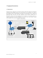
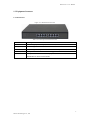
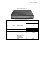
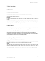
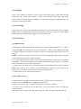
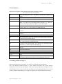
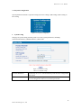
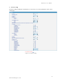
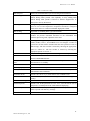
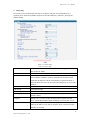
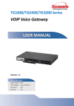
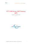
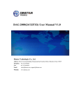
DAG Series User Manual V1.0
Dinstar Technologies Co., Ltd.
Address: Floor 6 Guoxing Building Changxing Road Nanshan District Shenzhen China 518057
Telephone:
86-755-26456664
Fax:
86-755-26456659
Email:
[email protected], [email protected]
Website:
www.dinstar.com
DAG Series User Manual
Revision Records
File Name
DAG Series User Manual
Document Version
Firmware Version
Date
Revised by
1.0
20.02.01
22/09/2011
Technical Support Department
Dinstar Technologies Co., Ltd.
DAG Series User Manual
Table of Contents
1. EQUIPMENT INTRODUCTION ........................................................................................................ 2
1.1 Introduction ......................................................................................................................... 2
1.2 Equipment Structure............................................................................................................ 3
1.2.1 Front View................................................................................................................ 3
1.2.2 Rear View ................................................................................................................. 4
1.3 Connect DAG serial ............................................................................................................ 5
1.4 Functions and Features ........................................................................................................ 6
1.4.1 Protocol standard supported ..................................................................................... 6
1.4.2 System function........................................................................................................ 6
1.4.3 Industrial standards supported.................................................................................. 6
1.4.4 General hardware specification ................................................................................ 6
2. BASIC OPERATIONS ......................................................................................................................... 8
2.1 Placing a Phone Call ........................................................................................................... 8
2.1.1 Phone or Extension Numbers ................................................................................... 8
2.1.2 Direct IP Calls .......................................................................................................... 8
2.2 Call Hold ............................................................................................................................. 9
2.3 Call Waiting ........................................................................................................................ 9
2.4 Call Transfer........................................................................................................................ 9
2.4.1 Blind Transfer .......................................................................................................... 9
2.4.2 Attended Transfer ..................................................................................................... 9
2.5 Call Features ..................................................................................................................... 10
2.6 Sending And Receiving Fax .............................................................................................. 10
3.CONFIGURATION GUIDE ............................................................................................................... 11
3.1 Configure LAN Port’s IP Address ..................................................................................... 11
3.2 Connect The DAG Serial By The Web Browser ............................................................... 11
3.2.1 Login ...................................................................................................................... 11
3.3 Configure The DAG serial Using The Web Browser ........................................................ 13
3.3.1 System Information ................................................................................................ 14
2.3.2 Statistics ................................................................................................................. 15
3.3.3 Network Configuration .......................................................................................... 15
3.3.4 System Configuration............................................................................................. 20
3.3.5 Digit Map ............................................................................................................... 25
3.3.6 Routing Configuration ........................................................................................... 26
3.3.7 Manipulation Configuration ................................................................................... 28
3.3.8 Advanced Configuration ........................................................................................ 30
3.3.9 Management Configuration ................................................................................... 32
4.FAQ ..................................................................................................................................................... 35
4.1 How to get the IP address if I have modified the default IP or forgot it ? ......................... 35
4.2 Device have been connected to network physically, but the network cannot be connected
or network communication is not normal ............................................................................... 35
Dinstar Technologies Co., Ltd.
DAG Series User Manual
4.3 Equipment can’t register ................................................................................................... 35
4.4 When calling out, the callee’s phone shows wrong caller ID ............................................ 35
4.5 When calling in, the caller always hears a busy tone ........................................................ 36
4.6 Sudden interruption during a call ...................................................................................... 36
5. GLOSSARY ....................................................................................................................................... 37
Dinstar Technologies Co., Ltd.
DAG Series User Manual
1. Equipment Introduction
1.1 Introduction
The DAG serial is a full feature voice and fax-over IP device that offers a high-level of integration
including dual 10M/100Mbps network ports with integrated router, NAT, DHCP server, dual port
FXS telephone gateway, market-leading sound quality, rich functionalities, and a compact and
lightweight design. The DAG serial fully compatible with SIP industry standard and can
interoperate with many other SIP compliant devices and software on the market. Moreover, it
supports comprehensive voice codecs including G.711 (a/μ-law), G.723.1 and G.729AB. A typical
network diagram shows the function of DAG serial as below.
Figure 1-1-1 Network Scenario
Anywhere In the World
IP PBX Server
IP Phone
Internet
FXO Lines
PSTN
PSTN
DAG1000(8FXO)
IP Phone
DAG1000(8FXS)
PSTN analog phones
PSTN analog phones
2
Dinstar Technologies Co., Ltd.
DAG Series User Manual
1.2 Equipment Structure
1.2.1 Front View
Figure 1-2-1 DAG Series Front View
Table 1-2-1 Description of DAG Front View
Interface
Description
PWR
Connecting to power adapter, 110~240VAC,50~60HZ,0.4A
WAN(RJ-45)
Connecting to internal LAN network or router
LAN(RJ-45)
Connecting to LAN port with an Ethernet cable to your PC
PHONE(RJ-11)
FXS ports should be connected to analog phones/fax machines
FXO
FXO ports should be connected to physical PSTN lines from a traditional
PSTN PBX or PSTN Central Office
3
Dinstar Technologies Co., Ltd.
DAG Series User Manual
1.2.2 Rear View
Figure 1-2-2 DAG Series Rear View
Table 1-2 -2 Description of DAG Series Rear View
LED
Color
Name
POWER
Green
Power status indicator
RUN
Green
Register indicator
WAN
Yellow
WAN status indicator
LAN
Yellow
LAN status indicator
Green
Indicate status of the
respective FXS ports on
the back
FXS
FXO
Green
Indicate status of the
respective FXO
ports-phone on the
back
Status
Description
Off
Power is off
On
Power is on
Fast blinking
Register
Slow blinking
Unregister
Off
Failed
On
Normal
Off
Failed
On
Normal
Off
Available
On
Busy
Off
Available
On
Busy
4
Dinstar Technologies Co., Ltd.
DAG Series User Manual
1.3 Connection to DAG serial
The DAG serial is easy to configure using the embedded GUI pages and the following five (5)
steps.
Five easy steps to configure the DAG serial
1. Connecting a standard touch-tone analog telephone (or fax machine) to first FXS port
2. Connecting another standard touch-tone analog telephone (or fax machine) to second FXS port
or connect PSTN line to line port(FXO)
3. Inserting the Ethernet cable into the WAN port of DAG serial and connecting the other end of
the Ethernet cable to an uplink port (a router or a modem, etc.)
4. Connecting a PC to the LAN port of DAG serial
5. Inserting the power adapter into the DAG serial and connecting it to a wall outlet
5
Dinstar Technologies Co., Ltd.
DAG Series User Manual
1.4 Functions and Features
1.4.1 Protocol standard supported
●
●
●
●
●
●
●
Standard SIP /MGCP protocol;
Simple Traversal of UDP over NATs (STUN);
IP Transport: RTP/RTCP
Hypertext Transfer Protocol (HTTP);
Dynamic Host Configuration Protocol (DHCP Server/Client);
Domain Name System (DNS);
ITU-T G.711A-Law/U-Law、G.723.1、G.729AB、G.168;
1.4.2 System function
●
●
●
●
●
●
●
PLC,VAD and CNG
DTMF mode: RFC 2833,SIP INFO and INBAND
T.38/ Pass-Through FAX over IP
HTTP/Telnet configuration
Firmware upgrade by TFTP/Web
QoS: Diffserve, TOS,802.1 P/Q VLAN tagging
Caller ID, Call waiting, Call transfer and DND
1.4.3 Industrial standards supported
●
●
●
●
●
●
●
●
●
●
Stationary use environment: EN 300 019: Class 3.1
Storage environment: EN 300 019: Class 1.2
Transportation environment: EN 300 019: Class 2.3
Acoustic noise: EN 300 753
CE EMC directive 2004/108/EC
EN55022: 2006+A1:2007
EN61000-3-2: 2006,
EN61000-3-3: 1995+A1: 2001+A2: 2005
EN55024: 1998+A1: 2001+A2: 2003
Certifications: FCC, CE
1.4.4 General hardware specification
●
●
●
●
●
Power supply: Output: 12VDC, Input 100~240 VAC/50HZ
Temperature: 0~40℃(operational),-20~70℃(storage)
Humidity: 10%~90%, no condensation
Max power consumption: 6/8/10/15/30W
Dimension(mm): DAG1000(1FXS):100*68*24, DAG1000(2FXS):160*110*30,
6
Dinstar Technologies Co., Ltd.
DAG Series User Manual
DAG1000(4FXS):195*133*35,DAG1000(4FXO/8FXS/8FXO):240*150*35,
DAG2000(16FXS/FXO):440*280*43
● Net weight: DAG1000(1FXS):0.1kg, DAG1000(2FXS):0.25kg,
DAG1000(4FXO/8FXS/8FXO):1kg, DAG2000(16FXS/16FXO):3.05kg
7
Dinstar Technologies Co., Ltd.
DAG Series User Manual
2. Basic Operations
2.1 Phone Call
2.1.1 Phone or Extension Numbers
1. Dial the number directly and wait for 3 seconds (Default “No dial timeout”);
2. Dial the number directly and press #.
Examples:
1. Dial an extension directly on the same proxy, (e.g. 8080), and then press the # or wait for 3
seconds.
2. Dial an outside number (e.g. (626) 666-8080), first enter the prefix number (usually 1+ or
international code) followed by the phone number. Press # or wait for 3 seconds. Check with your
VoIP service provider for further details on prefix numbers.
2.1.2 Direct IP Calls
Direct IP calling allows two parties, that is, a FXS Port with an analog phone and another VoIP
Device, to talk to each other in an ad hoc fashion without a SIP proxy.
Elements necessary to completing a Direct IP Call:
1. Both DAG serial and other VoIP Device, have public IP addresses;
2. Both DAG serial and other VoIP Device are on the same LAN using private IP addresses;
3. Both DAG serial and other VoIP Device can be connected through a router using public or
private IP addresses (with necessary port forwarding or DMZ).
1. Pick up the analog phone then dial “*47”
2. Enter the target IP address.
Note: No dial tone will be played between step 1 and 2.
Examples:
If the target IP address is 192.168.0.160, the dialing convention is *47, then 192*168*0*160.
Followed by pressing the “#” key or wait 3 seconds. Destination port is 5060.
NOTE:
You cannot make direct IP calls between FXS0 to FXS1 since they are using same IP. It only
supports the default destination port 5060. “Disable direct IP-IP calling” must be set to “No” in
web configuration page. “Call features enable” must be set to “Yes” in web configuration page.
8
Dinstar Technologies Co., Ltd.
DAG Series User Manual
2.2 Call Hold
Place a call on hold by pressing the “flash” button on the analog phone (if the phone has that
button).Press the “flash” button again to release the previously held Caller and resume
conversation. If no “flash” button is available, use “hook flash” (toggle on-off hook quickly). You
may drop a call using hook flash.
2.3 Call Waiting
Call waiting tone (3 short beeps) indicates an incoming call, if the call waiting feature is enabled.
Toggle between incoming call and current call by pressing the “flash” button. First call is placed
on hold. Press the “flash” button to toggle between two active calls.
2.4 Call Transfer
2.4.1 Blind Transfer
Assume that call Caller A and B are in conversation. A wants to Blind Transfer B to C: 1. Caller A
presses FLASH on the analog phone to hear the dial tone. 2. Caller A dials *87 then dials caller
C’s number, and then # (or wait for 4 seconds) 3. Caller A will hear the confirm tone. Then, A can
hang up.
NOTE: “Call features enable” must be set to “Yes” in web configuration page. Caller A can place
a call on hold and wait for one of three situations:
1. A quick confirmation tone (similar to call waiting tone) followed by a dial-tone. This indicates
the transfer is successful (transferee has received a 200 OK from transfer target). At this point,
Caller A can either hand up or make another call.
2. A quick busy tone followed by a restored call (on supported platforms only). This means the
transferee has received a 4xx response for the INVITE and we will try to recover the call. The
busy tone is just to indicate to the transferor that the transfer has failed.
3. Continuous busy tone. The phone has timed out.
2.4.2 Attended Transfer
Assume that Caller A and B are in conversation. Caller A wants to Attend Transfer B to C:
1. Caller A presses FLASH on the analog phone for dial tone.
2. Caller A then dials Caller C’s number followed by # (or wait for 3 seconds).
3. If Caller C answers the call, Caller A and Caller C are in conversation. Then A can hang up to
complete transfer.
4. If Caller C does not answer the call, Caller A can press “flash” to resume call with Caller B.
9
Dinstar Technologies Co., Ltd.
DAG Series User Manual
2.5 Call Features
The DAG serial supports all the traditional and advanced telephony features.
Table 5.DAG serial Call Feature Definitions
*47
Direct IP Calling. Dial “*47” + “IP address”. No dial tone is played in the
middle.
*50
Disable Call Waiting(for all subsequent calls)
*51
Enable Call Waiting(for all subsequent calls)
*72
Unconditional Call Forward:
Dial “*72” and then the forwarding number followed by “#”. Wait for
dial tone and hang up. (dial tone indicates successful forward)
*73
Cancel Unconditional Call Forward: To cancel “Unconditional Call
Forward”, dial “*73”, wait for dial tone, and then hang up.
*78
Enable Do Not Disturb(DND): When enabled all incoming calls are
rejected
*79
Disable Do Not Disturb(DND): When disabled, incoming calls are
accepted.
*87
Blind Transfer
*90
Busy Call Forward: Dial “*90” and then forwarding number followed by
“#”.Wait for dial tone then hang up.
*91
Cancel Busy Call Forward. To cancel “Busy Call Forward”, dial
“*91”,wait for dial tone, and then hang up.
*92
No Answer Call Forward. Dial “*92” and then the forwarding number
followed by “#”. Wait for dial tone then hang up.
*93
Cancel No Answer Call Forward. Dial “*93”, wait for dial tone, and then
hang up.
*99
Cancel all call forward
*114#
Report phone No
*158#
Report IP Address
*111#
Reset
Flash/Hook
Toggles between active call and incoming call(call waiting tone). If not in
conversation, flash/hook will switch to a new channel for a new call.
2.6 Sending and Receiving Fax
DAG serial supports fax in two modes: 1) T.38 (Fax over IP) and 2) fax pass through.
T.38 is the preferred method because it is more reliable and works well in most network
conditions. If the service provider supports T.38, please use this method by selecting T.38 as fax
mode (default). If the service provider does not support T.38, pass-through mode may be used. If
you have problems with sending or receiving Fax, toggle the Fax Tone Detection Mode setting.
10
Dinstar Technologies Co., Ltd.
DAG Series User Manual
3. Configuration Guide
3.1 Configure LAN Port’s IP Address
Connect to the FXS port and then telephone set:
1. Dynamic IP address by DHCP:
Offhook;
Input “*150*2#”;
Onhook;
If the equipment hint success, after 10 seconds, and restart the equipment. (Power-off then
power-on)
2. Static IP address:
Offhook;
Input “*150*1#”;
Onhook;
Then
(1) Configure IP address:
Offhook; input “*152*172*16*0*100# ”; onhook.
(2) Configure netmask:
Offhook; input “*153*255*255*0*0# ”; onhook.
(3) Configure gateway IP address (next hop):
Offhook; input “*156*172*16*0*1# ”; onhook.
(4) if success, after 10 seconds, restart the equipment ;
3. Query the IP address of DAG1000 : Offhook, input “*158#”
4. If the DAG serial uses PPPoE method to get IP address,it need to configure by web browser.
NOTE: the telephone will play voice hint “Setting successfully” if the setting step is correct.
3.2 Access DAG Serial By Web Browser
DAG serial has an embedded Web server that will respond to HTTP GET/POST requests. It also
has embedded HTML pages that allow users to configure the DAG serial through a web browser
such as Microsoft’s IE .
3.2.1 Login
The DAG serial GUI configuration can be accessed via LAN or WAN port:
From the LAN port
1. Offhook, input *158# and get an IP address. The default gateway IP address: 192.168.11.1.
2. Directly connect a computer to the LAN port.
3. Open a command window on the computer.
4. Type in “ipconfig /release”, the IP address etc. becomes 0.
5. Type in “ipconfig /renew”, the computer gets an IP address in 192.168.11.x segment by default
11
Dinstar Technologies Co., Ltd.
DAG Series User Manual
6. Open a web browser, input the default gateway IP address. http://192.168.11.1. You will see the
login page of the device.
7. The default username is admin while the default password is admin too.
From the WAN port
The WAN port HTML configuration option is disabled by default from factory. To access the
HTML configuration menu from the WAN port:
1. Access the Web from LAN port.
2. Set Work Mode to Route Mode.
3. Enable the “Remote Manage”.
4. Find the WAN IP address of the equipment .example:172.16.0.177 then restart the equipment.
5. Access the equipment Web Configuration page by the following URI via WAN port: http://
172.16.0.177
12
Dinstar Technologies Co., Ltd.
DAG Series User Manual
3.3 Access DAG serial by Web Browser
The web page configuration includes the following:
Figure 3-3-1 Navigation tree
Go through navigation tree, user can check, modify, and set the device configuration on the right
of configuration interface.
Figure3-3-1 Configure Interface
13
Dinstar Technologies Co., Ltd.
DAG Series User Manual
3.3.1 System Information
Figure 3-3-2 System Information
System information interface shows the run information and port group information.
Table 3-3-1 Description of System Information
MAC address
The device ID in HEX format. This is needed for ISP
troubleshooting. Note there are separate MAC addresses for the
WAN side and the LAN side.
Network Mode
Route mode or bridge mode, if it is bridge, WAN port display
Network, and the WAN port as same as the LAN port
WAN port
Show WAN IP address of equipment,.
DHCP mode:
The equipment acquires its IP address from the first DHCP server it
discovers from the LAN it is connected.
Static IP mode:
Configure the IP address, Subnet Mask, Default Router IP address,
DNS Server 1 (primary), DNS Server 2 (secondary) fields. These
fields are set to zero by default.
LAN port
Show LAN IP address of equipment. If network mode is bridge,
LAN port will no display.
DNS Server
IP addresses of primary DNS server
System Up Duration
Time elapsed from device power on to now.
Network Traffic Statics
Total bytes of message received and sent by network port.
Version Information
Includes: product mode, software version, hardware version and
built time etc.
Port Group Information
Show FXS / FXO port information
14
Dinstar Technologies Co., Ltd.
DAG Series User Manual
2.3.2 Statistics
Figure3-3-3 Statistics
Statistics option includes three sets of statistics: TCP / UDP information, RTP messages and call
history information. Check the user-friendly equipment failure.
3.3.3 Network Configuration
Network parameter includes: Local Network, VLAN Config, Qos Parameter, ARP Config.
Figure 3-3-4 Network Configuration
15
Dinstar Technologies Co., Ltd.
DAG Series User Manual
1. Local Network
Figure 3-3-5 Local Network
Table 3-3-2 Description Local Network
Work Mode
This parameter controls whether the device is working in NAT
router mode or Bridge mode.
WAN Port Parameter
This option specifies the WAN port’s Ip address, and its Ethernet
network work mode.
Link speed & duplex This option specifies the Ethernet
network’s work mode. It have: Auto Detect,10Mbps/Half
Duplex,10Mpbs/Full Duplex,100Mbps/Half Duplex,
100Mpbs/Full Duplex, There are three modes to operate the
DAG serial WAN IP address, default option is Dynamically
assigned via DHCP.
Dynamically assigned via DHCP: All the field values for the
Static IP mode are not used. The equipment acquires its IP
address from the first DHCP server it discovers from the LAN it
is connected.
Static IP mode: Configure the IP address, Subnet Mask, Default
Router IP address, DNS Server 1 (primary), DNS Server 2
(secondary) fields. These fields are set to zero by default.
Dynamically assigned via PPPoE : Set the PPPoE account
settings. The equipment will establish a PPPoE session if any of
the PPPoE fields is set.
16
Dinstar Technologies Co., Ltd.
DAG Series User Manual
LAN Port Config
This option specifies the LAN port’s ip address, and its Ethernet
network work mode.
Link speed & duplex:
This option specifies the Ethernet network’s work mode. It have:
Auto Detect,10Mbps/Half Duplex,10Mpbs/Full
Duplex,100Mbps/Half Duplex,100Mpbs/Full Duplex.
IP address: Set LAN IP address, default value is 192.168.11.1
Subnet mask: Sets the LAN subnet mask. Default value is
255.255.255.0
DNS Server
This option specifies get the DNS server ways: Dynamically
assigned via DNS(WAN IP address is DHCP IP) and set static
DNS (WAN IP address is static IP).
17
Dinstar Technologies Co., Ltd.
DAG Series User Manual
2. VLAN Parameter Config
Figure 3-3-6 VLAN Parameter Config
When a network has a very wide range of applications, in order to artificially divided into different
applications to different networks, to prevent them interfering with each other and to different
networks with different bandwidth, customer can use the VLAN.
VLAN parameter configuration can configure three VLAN as follows.
(1)Data VLAN
Data VLAN use the
default WAN interface in
this case
Selecting “Enable” will configure Data VLAN.
Data 802.1Q VLAN
ID(0-4095)
Fill out an ID to describe a D ata VLAN group.
Data 802.1p Priority(0-7)
802.1 protocol to control network traffic priority, Priority from 0-7.
Obtain IP address
automatically
Select this to automatically obtain the IP of VLAN group
Use the following IP
address
Fill in IP, Subnet mask and Default Gateway
Dynamically assigned via
PPPoE
Select this when the Internet through PPPOE and complete account
number and password
18
Dinstar Technologies Co., Ltd.
DAG Series User Manual
(2)Voice VLAN
Voice 802.1Q VLAN ID (0-4095)
Fill out an ID to describe a Voice VLAN group.
Voice 802.1p Priority(0-7)
802.1 protocol to control network traffic priority, Priority
from 0-7.
Obtain IP address automatically
Select this to automatically obtain the IP of VLAN group
Use the following IP address
Fill in IP, Subnet mask and Default Gateway
(3)Management VLAN
Management 802.1Q VLAN ID
(0-4095)
Fill out an ID to describe a Management VLAN group.
Management 802.1p Priority(0-7)
802.1 protocol to control network traffic priority, Priority
from 0-7.
Obtain IP address automatically
Select this to automatically obtain the IP of VLAN group
Use the following IP address
Fill in IP, Subnet mask and Default Gateway
3. Qos Parameter
Figure 3-3-7 Qos Parameter
DSCP code point is used for diffserv setting. It utilizes the first 6 bits of IP ToS. You can use
different DSCP for voice or data according to the network provider.
4. ARP Config
Figure 3-3-8 ARP Config
Manually add the address resolution.
19
Dinstar Technologies Co., Ltd.
DAG Series User Manual
3.3.4 System Configuration
System parameter includes 1) System Config 2) Service Config 3) SIP Config 4) Port Config 5)
Fax Config.
Figure 3-3-9 System Configuration
1. System Config
The page of system setting is mainly used to set some system parameters, including:
1)Provision Parameter; 2)NTP Parameter; 3)Time Zone
Figure 3-3-10 System Config
Table 3-3-3 System Config
Provision Parameter
Periodically, the server will automatically load the latest configuration
and version
NTP Parameter
NTP server management system time. Select "NTP Enable" to "YES",
you can configure the NTP server's IP and system time.
20
Dinstar Technologies Co., Ltd.
DAG Series User Manual
2. Service Config
In order to adapt to different environments, it is necessary to set some parameters in the service
config page.
Figure 3-3-11 Service Config
21
Dinstar Technologies Co., Ltd.
DAG Series User Manual
Table 3-3-4 Service Config
RTP start port
Defines the local RTP-RTCP port for listening and transmission.
Silence Suppression
Endpoints sending audio as an RTP stream are not required to send
packets during silent periods. The capability to stop sending RTP
packets during silent periods is known as "Silence Suppression" or
VAD (Voice Activity Detection).
Call Progress Tone
Configure ring or tone frequencies according to preference. By default
tones are set to USA frequencies. Frequencies should be configured
with known values to avoid uncomfortable high pitch sounds.
SLIC Setting
Dependent on standard phone type (and location).
Hook Flash Detect
Time period when the cradle is pressed (Hook Flash) to simulate
FLASH. To prevent unwanted activation of the Flash/Hold and
automatic phone ring-back, adjust this time value.
Preferred Vocoder
The equipment supports up to 4 different vocoder types including
PCMU, PCMA, G.723.1, G.729AB.The user can configure vocoders in
a preference list that will be included with the same preference order in
SDP message. The first vocoder is entered by choosing the appropriate
option in “Choice 0”. The last vocoder is entered by choosing the
appropriate option in “Choice 3”.
FXO Parameter
Many FXO configuration parameters to configure the FXO port
DTMF
Flexible DTMF transmission method, user interface of in-audio,
RFC2833/INBAND/SIGNAL.
SDP parameter when
hold
When the call was hold ,the invitation of SDP the parameters can be
carried inactive or sendonly.
STUN
IP address or port of the STUN server
Incoming display
Caller ID There are two options: the name and number
Polarity Reversal
Default is No. If set to Yes, polarity will be reversed upon call
establishment and termination.
Send Flash Event
Default is NO. If set to yes, flash will be sent as DTMF event
Call Features
Default is Yes. (If Yes, call features using star codes will be supported
locally)
Direct IP-IP Calling
Default is NO
Send Anonymous
Default is No. If this parameter is set to “Yes”, users ID will be sent as
anonymous; essentially block the Caller ID from displaying.
Reject Anonymous Call
Default is NO. If set to yes, incoming calls with anonymous Caller ID
will be rejected with 486 busy message.
No Dial Timeout
Default is 4 seconds
22
Dinstar Technologies Co., Ltd.
DAG Series User Manual
3. SIP Config
It is used to set the local SIP port, the SIP server address and port. If an outbound proxy is
required, please fill in the IP address and port of the outbound proxy; otherwise, just keep the
default settings.
Figure 3-3-12 SIP Config
Table 3-3-5 SIP Config
Primary SIP Server
Fill the SIP Server IP address, Port(default:5060), Register
Interval(default:1800s)
Secondary SIP Server
The SIP server as a backup
Outbound proxy
IP address or Domain name of Outbound Proxy, or Media Gateway, or
Session Border Controller. Used by equipment for firewall or NAT
penetration in different network environments. If symmetric NAT is
detected, STUN will not work and only outbound proxy can correct the
problem.
Subscribe for MWI
Default is No
VM user ID
Voice Mail user ID
Use random port
If selected “Yes”, the port number will be randomly generated
Local sip port
If “Use random port” option was set to “No”, this option will be used.
Default is 5060.
Is register
Default is Yes, if it was set No, the stand will not register the SIP
server, and the RUN LED will quick blinking (resisted status is Yes)
Keepalive interval
This parameter specifies how often the equipment sends a blank UDP
packet to the SIP server in order to keep the “hole” on the NAT open.
Default is 10 seconds.
23
Dinstar Technologies Co., Ltd.
DAG Series User Manual
4. Port Config
This page is used to config the account and password of DAG serial, call transfer, call waiting and
do-not-disturb service. Port 0 maps to FXS0, while Port n maps to FXS n.
Figure 3-3-13 Port Config
Table 3-3-6 Port Config
Current Port
Select configure a SIP trunk port
TX/RX Gain
Handset volume adjustment. RX is for receiving volume, TX is
for transmission volume. Default values are -6dB for both
parameters. Loudest volume: +6dB Lowest volume: -6dB.
Offhook Auto-Dial
Fill in the number of offhook auto-dial
Enable DND
Default is No. When enabled all incoming calls are rejected.
Enable Caller-ID
Default is Yes
SIP User ID
SIP count number
Authenticate ID
SIP user name which registers to soft switch/SIP server
Authenticate password
SIP password which registers to soft switch/SIP server
Call Forwarding Unconditional
All incoming calls are transferred appointed phone.
Call Forwarding Busy
Call will transfer appointed phone when Busy.
Call Forwarding No Reply
Call will transfer appointed phone when nobody answer the
call.
Disable Call Waiting
Default is No. User can use * code to use this feature per call
basis.
Disable Call Waiting Tone
Default is No. Indicates an incoming call,default is 2 short
beeps.
24
Dinstar Technologies Co., Ltd.
DAG Series User Manual
5. Fax Config
Figure 3-3-14 Fax Config
Table 3-3-7 Fax Config
Fax mode
T.38 (Auto Detect) FoIP by default, or Pass-Through
Fax tone detection mode
Default is Automatic. There are callee and caller two options
ECM
Error Correction Mode
Fax rate
The equipment support most 14400bps least 2400bps fax rate. The
default value is 14400bps.
3.3.5 Digit Map
Figure 3-3-15 Digit Map
In the "digit map" set dial rules and dialing rules can’t exceed 120 characters in length.
25
Dinstar Technologies Co., Ltd.
DAG Series User Manual
3.3.6 Routing Configuration
1. Routing Parameter
Figure 3-3-16 Routing Parameter
This option determines the following routing of call take effect before or after manipulation.
2. IP in Routing
Figure 3-3-17 IP in Routing
Figure 3-3-18 IP in Routing Add
Table 3-3-8 IP in Routing Add
Index
Routing priority :1-30
Description
Description the routing
Source Prefix
Source number Prefix
Source
IP Trunk/SIP Server, any means wildcard string
Destination Prefix
Destination number Prefix
Destination
Select a single port or port group
26
Dinstar Technologies Co., Ltd.
DAG Series User Manual
3. Tel in Routing
Figure 3-3-19 Tel in Routing
Figure 3-3-20 Tel in Routing Add
Table 3-3-9 Tel in Routing Add
Index
Routing priority :1-30
Description
Description the routing
Source Prefix
Source number Prefix
Source
Select a single port or port group
Destination Prefix
Destination number Prefix
Destination
Select a single port or port group, IP Trunk/SIP Server
27
Dinstar Technologies Co., Ltd.
DAG Series User Manual
3.3.7 Manipulation Configuration
1. IP in Destination Numbers
Figure 3-3-21 IP in Destination Numbers
Figure 3-3-22 IP in Destination Numbers Add
Table 3-3-10 IP in Destination Numbers Add
Index
Routing priority :1-30
Description
Description the routing
Source Prefix
Source number Prefix
Source
IP Trunk/SIP Server, any means wildcard string
Destination Prefix
Destination number Prefix
Destination
Select a single port or port group
Stripped Digits from Left
Remove the called number digits from the left
Stripped Digits from Right
Remove the called number digits from the right
Prefix to Add
Add a number prefix
Suffix to Add
Add a number suffix
Number of Digits to Leave
from Right
Starting from the right to retain the called number digits
28
Dinstar Technologies Co., Ltd.
DAG Series User Manual
2. Tel in Source Numbers
Figure 3-3-23 Tel in Source Numbers
Figure 3-3-24 Tel in Source Numbers Add
Configuration parameters are the same with “IP in Source Numbers Add”.
3.Tel in Destination Numbers
Figure 3-3-25 Tel in Destination Numbers
Configuration parameters are the same with “IP in Source Numbers Add”.
29
Dinstar Technologies Co., Ltd.
DAG Series User Manual
3.3.8 Advanced Configuration
1. Port Group
Figure 3-3-26 Port Group
Figure 3-3-27 Port Group Add
Table 3-3-11 Port Group Add
Index
Priority of the port group :1-7, 1 is highest priority value.
Description
Descript the port group
Primary/Secondary SIP User ID
SIP count number
Primary/Secondary Authenticate ID
SIP user name which registers to soft switch/SIP server
Primary/Secondary Authenticate
Password
SIP password which registers to soft switch/SIP server
Select Mode
There four options: Ascending, Cyclic Ascending,
Descending, Cyclic Descending
Port
Port0-port7, By checking the different ports to form a port
group
30
Dinstar Technologies Co., Ltd.
DAG Series User Manual
2. IP Trunk
Figure 3-3-28 IP Trunk Add
Table 3-3-12 IP Trunk Add
Index
64 Priority values from 0-63
IP
Set port IP
Port
Set port number
Description
The description of IP trunk
31
Dinstar Technologies Co., Ltd.
DAG Series User Manual
3.3.9 Management Configuration
1. Firmware Upload
Figure 3-3-29 Firmware Upload
Table 3-3-13 Firmware Upload Add
Software
Click "Browse" to select the firmware , and then click "Upload".
2. Config Backup
Figure 3-3-30 Data Backup
Click the Backup, and save the configuration file in your PC.
3. Config Restore
Figure 3-3-31 Data Restore
Click "Browse" to select the Configuration file, and then click "Restore".
4.System Log
Figure 3-3-32 Syslog Config
32
Dinstar Technologies Co., Ltd.
DAG Series User Manual
Table 3-3-14 Syslog Config
Enable Syslog
Default is No
Server Address
Storage system log server address
Syslog Level
At present only two options(None and Debug) are available
Send CDR
Default is No
5. Ping Test
Figure 3-3-33 Ping Test
Table 3-3-15 Ping Test
Ping Destination
Destination IP address
Number of Ping(1-100)
Number of ICMP packets
Ping Packet Size(56-1024 bytes)
Length of Packet
6. Tracert Test
Figure 3-3-34 Tracert Test
Fill “Tracert Destination IP” and “Max hops of tracert(1-255)”, then click “start”, tracking
information will be displayed in the space below.
33
Dinstar Technologies Co., Ltd.
DAG Series User Manual
7. Login Password
Modify login user name and password to avoid unauthorized access to your DAG serial . The
default username is admin while the default password is admin too.
Figure 3-3-35 Login Password
8. Factory Reset
Figure 3-3-36 Factory Reset
Click “Apply” to restore the factory settings.
9. Restar
Figure 3-3-37 Restar
Click the “Save” button in the Configuration page to save the changes to the equipment
configuration. The following screen confirms that the changes are saved. If the changes need
restart, reboot or power cycle the equipment to make the changes take effect.
34
Dinstar Technologies Co., Ltd.
DAG Series User Manual
4. FAQ
4.1 How to get the IP address if I have modified the default IP or forgot it ?
Customers have two ways to get the IP address.
1) Press the RST button, then customer can retain the default IP of LAN port.
2) Analog telephone by dialing "*", re-set the IP address, refer to 3.1.
4.2 Device have been connected to network physically, but the network cannot be
connected or network communication is not normal
1) Make sure the network cable is ok or not , can through view the device WAN port or LAN port
indicator light to determine the work states of physical connection;
2) Make sure the connected network devices (router, switch or hub) support 10M/100M adaptive.
Else, connecting the Equipment directly to PC and landing WEB , then in the "local connection"
Selecting the correct Ethernet Work Mode;
3) Check the Network Configuration, if the Configuration is incorrect, please re-Configuration. If
customers are using DHCP mode, so check whether DHCP Server work properly;
4) Check whether there is a LAN port conflict with the existing IP address.
4.3 Equipment can’t register
If the Run LED flashes slowly ,it means unregistered.
1) Check the network connection is working (see above section), whether the Configuration is
correct;
2) Check whether the LAN firewall setting is inappropriate (such whether limit the network
Communication); If it is, there are two ways to try to resolve:
(1) Ask network administrators to open limitation with the equipment’s network communications
(it is a special equipment, not afraid of virus attacks); (2) Try to enable the equipment tunnel
(Through the WEB for Configuration, Also, please NOTE, open the tunnel will impact voice
quality, Please do not enable the tunnel as far as possible, reference WEB Configuration Interface
Description section);
4) Check whether the Local Network to the SIP PROXY platform network environment is
relatively poor or not, and if so, please check Local Network or contact the service provider;
5) If go through those steps, the device still be in trouble, please contact the equipment provider;
4.4 When calling out, the callee’s phone shows wrong caller ID
1) Ask the callee checks whether the device is failure or device battery power is low
2) Make sure the callee has been subscribed called User ID display service
35
Dinstar Technologies Co., Ltd.
DAG Series User Manual
3) If only part of the caller User ID with this problem, please contact the telecom carrier.
4.5 When calling in, the caller always hears a busy tone
Make sure enable DND(Do-not-Disturb) in system
4.6 Sudden interruption during a call
1) make sure whether is human error caused the problem
2) Make sure with the account balance or lack of disruption caused the call disconnected
3) Make sure whether there is interference with the fax tone or equipment busy tone, these
interference may lead to calls dropped
4) Make sure whether the LAN equipment such as gateway or router fails, user can try to restart
the gateway or router please download tutorials from our official website .
36
Dinstar Technologies Co., Ltd.
DAG Series User Manual
5. Glossary
ADSL Asymmetric Digital Subscriber Line: Modems attached to twisted pair copper wiring that transmit
from 1.5 Mbps to 9 Mbps downstream (to the subscriber) and from 16 kbps to 800 kbps upstream,
depending on line distance.
AGC Automatic Gain Control is an electronic system found in many types of devices. Its purpose is to
control the gain of a system in order to maintain some measure of performance over a changing range
of real world conditions.
ARP Address Resolution Protocol is a protocol used by the Internet Protocol (IP) [RFC826], specifically
IPv4, to map IP network addresses to the hardware addresses used by a data link protocol. The
protocol operates below the network layer as a part of the interface between the OSI network and OSI
link layer. It is used when IPv4 is used over Ethernet
CODEC Abbreviation for Coder-Decoder. It's an analog-to-digital (A/D) and digital-to-analog (D/A)
converter for translating the signals from the outside world to digital, and back again.
CNG Comfort Noise Generator, generate artificial background noise used in radio and wireless
communications to fill the silent time in a transmission resulting from voice activity
detection.
DATAGRAM A data packet carrying its own address information so it can be independently
routed from its source to the destination computer
DECIMATE To discard portions of a signal in order to reduce the amount of information to be
encoded or compressed. Lossy compression algorithms ordinarily decimate while
sub-sampling.
DNS Short for Domain Name System (or Service or Server), an Internet service that translates
domain names into IP addresses
DSP Digital Signal Processor. A specialized CPU used for digital signal processing. Allywll
products all have DSP chips built inside.
DTMF Dual Tone Multi Frequency. The standard tone-pairs used on telephone terminals for
dialing using in-band signaling. The standards define 16 tone-pairs (0-9, #, * and A-F)
although most terminals support only 12 of them (0-9, * and #).
FXO Foreign exchange Office. An FXS device can be an analog phone, answering machine, fax,
or anything that handles a call from the telephone company like AT&T. They should also
operate the same way when connected to an FXS interface. • An FXS interface will accept
calls from FXS or PSTN interfaces. All countries and regions have their own standards. •
FXS is complimentary to FXS (and the PSTN).
FXS Foreign exchange Station. An FXS device has hardware to generate the ring signal to the
FXS extension (usually an analog phone). • An FXS device will allow any FXS device to
operate as if it were connected to the phone company. This makes your PBX the
POTS+PSTN for the phone. • The FXS Interface connects to FXS devices (by an FXS
interface, of course).
DHCP The Dynamic Host Configuration Protocol (DHCP) is an Internet protocol for automating
the configuration of computers that use TCP/IP. DHCP can be used to automatically assign IP
addresses, to deliver TCP/IP stack configuration parameters such as the subnet mask and
default router, and to provide other configuration information such as the addresses for
37
Dinstar Technologies Co., Ltd.
DAG Series User Manual
printer, time and news servers.
ECHO CANCELLATION Echo Cancellation is used in telephony to describe the process of
removing echo from a voice communication in order to improve voice quality on a telephone
call. In addition to improving quality, this process improves bandwidth savings achieved
through silence suppression by preventing echo from traveling across a network. There are
two types of echo of relevance in telephony: acoustic echo and hybrid echo. Speech
compression techniques and digital processing delay often contribute to echo generation in
telephone networks.
H.323 A suite of standards for multimedia conferences on traditional packet-switched networks.
HTTP Hyper Text Transfer Protocol; the World Wide Web protocol that performs the request and
retrieves functions of a server
IP Internet Protocol. A packet-based protocol for delivering data across networks
IP-PBX IP-based Private Branch Exchange
38
Dinstar Technologies Co., Ltd.