1
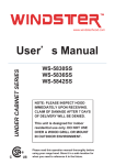
General user manual
Veneto ///
Range hoods
CHIMNEY HOOD WALL:
VT-ANG30, VT-ANG36,VT-ANG650, VT-VIT30, VT-VIT36, VT-ZEN2, VT-ZEN30,
VT-ZEN36,VT-ZEN650 VT-BAC30
ISALND HOOD:
VT-ANG36IL, VT-VIT36IL, VT-ZEN36IL, VT-ZEN3612IL, VT-ZEN42IL
UNDER CABINET HOOD :
VT-REG30,VT-REG30W,VT-CON30
PRO UNDER CABINET HOOD: VT-PROC30,VT-PROC36
INSERT HOOD:
VT-IN2816, VT-IN2812
1
Summary
Safety Notice….............................................................................................................................3-4
Electrical requirements and installation requirements..................................................................5
Examples and positioning possibilities for ducts............................................................................6 to12
Clearance……............................................................................................................................ 13
Necessary Tools .………………………………………..…………………………………………………………….…………..14
Installation Drawings and Dimensions ………………………………………………………………………………...15 to 28
Maintenance.............................................................................................................................29
warranty...................................................................................................................................30
Safety Notice
APPROVED FOR RESIDENTIAL TYPE UNITS FOR RESIDENTIAL USE ONLY READ THESE INSTRUCTIONS AND BE
SAFE.
PLEASE READ THESE INSTRUCTIONS COMPLETELY BEFORE STARTING.
THE INSTALLATION OF THE APPLIANCE MUST RESPECT ALL CODES.
IMPORTANT: Save these instructions so that you can provide the electrical inspector in your area.
Safety Warning: Turn off the circuit in the electrical panel and lock the front panel to connect the cord of this unit.
Power requirement: 110V-120V/60HZ
CAUTION: USE THIS PRODUCT FOR GENERAL FAN ONLY. DO NOT USE THIS PRODUCT TO EXHAUST FUMES
OR HAZARDOUS OR EXPLOSIVE MATERIALS. WARNING: TO REDUCE THE RISK OF FIRE, ELECTRICAL SHOCK
OR INJURY TO PEOPLE, OBSERVE THE FOLLOWING:
1. Use this unit only for the purposes intended by the manufacturer. If you have any questions about the product, contact
the manufacturer.
2. Before the machine's maintenance or cleaning, turn off the electrical panel and lock the panel blocking feature to
prevent from accidentally activating the power. If it is not possible to lock the access panel, attach a highly visible label to
the electrical panel.
3. A qualified person should perform the installation and wiring of the electricity in accordance with all codes and all
standards, including fire resistance rating.
4. It is important to provide sufficient air for proper combustion of heating equipment and proper evacuation of gases
through the chimney pipe to prevent back flow of air. Follow the instructions and safety standards of the manufacturers of
heating equipment, such as those published by the National Fire Protection Association (NFPA), the American Society for
Heating, Refrigeration and Air Conditioning Engineers (ASHRAE) and the code authorities in your area.
5. When cutting or drilling into wall or ceiling, be sure not to damage electrical wiring or other access to public service.
6. Always evacuate outside the conduit system.
To reduce the risk of fire and to properly exhaust air, be sure that the pipe is leading outside, do not exhaust air into the
space between the walls, ceilings, attics, crawl spaces or garages.
WARNING: TO REDUCE THE RISK OF FIRE, USE ONLY METAL DUCT. Install this hood in accordance with all the
requirements mentioned.
WARNING: TO REDUCE THE RISK OF FIRE, GREASE THE RANGE.
1. Never leave the stove unattended when it is at a high temperature. Boil overs cause smoke and fat that overflows can
ignite. Heat the oil slowly at a low or medium temperature.
2. Always operate the hood when you use the stove to high heat or when you
Flambé (Eg. Crepes Suzette, Cherries Jubilee, Peppercorn Beef Flambé).
3. Clean ventilating fans frequently. Do not let fat accumulate on the filters or propellers
4. Use proper pan size. Always use a pot size appropriate to the stove element
3
WARNING
TO AVOID INJURING SOMEONE IN A GREASE FIRE, FOLLOW THE FOLLOWING:
1. SMOTHER FLAMES with a lid to the dimensions of the cooking hobs, a cookie sheet or other metal tray, then turn
off the gas or power supply of the stove. BE CAREFUL NOT TO BURN YOURSELF. If the flames do not go out
immediately, LEAVE AND CALL THE FIRE DEPARTMENT.
2. NEVER PICK UP A FLAMING PAN, you could hurt yourself.
3. DO NOT USE WATER, including Dish towels or wet towels - a violent steam explosion of dew may occur.
4. Use an extinguisher ONLY if:
. You are sure to have a Class ABC extinguisher that you know how to use.
. The fire is small and confined to the area where it was formed.
. Firefighters were called.
. You can fight against the fire with an exit behind you.
operative MODE
1. Always leave safety grills and filters in place. Without the presence of these, blowers could catch hair, fingers or
clothing. The manufacturer is not liable if detailed in this manual for installation information, maintenance and proper
use of the product are not observed. The manufacturer declines all responsibility for any injury caused by negligence.
In addition, Product Warranty will be voided due to improper maintenance conditions. This product is manufactured
for internal use. Do not use this appliance outdoors.
CAUTION
Automatically controlled device - to reduce the risk of injury, unplug the power supply before repair. The device is
equipped with a switch integration.
Electrical requirements and installation requirements
Power Requirements
IMPORTANT
Observe all governing codes and ordinances. The customer is responsible for: Contacting an electrician-installer. Check that the
electrical installation is adequate and in conformance with the National Electrical Code, ANSI / NFPA 70 (latest edition *) or CSA
Standards C22.1-94, Canadian Electrical Code, Part 1 and C22.2 No.0-M91 (the latest edition **) of the CSA, and all codes and
ordinances in your area. If codes permit and use a wire to separate the ground, it is recommended to check the path of the wire
by an electrician. Do not put the device to land on a gas line. Consult a qualified person if you are not sure that the hood is
properly grounded electrically. Do not install a fuse in the neutral circuit or circuit ground.
Location of the electrical installation
• The cable must enter the rear wall at least 20 to 1/4 "above the height of the installation base, and between 7-5/8" and 4-7/8
"from the left side of the midline.
MPORTANT
Keep these instructions in order to return them to the electrical inspector. The hood must be plugged directly into a 110 volt wall
outlet.
Before installing the hood
1. To ensure the most efficient ventilation possible, install the pipe in a straight line or with the least elbows possible.
CAUTION: The output of the vent pipe should give to the outside.
2. Two people are required for installation.
3. Supplied hardware can secure the hood to most walls and ceilings, consult a qualified installer to ensure that the hardware provided is suitable for your type of
wall or cabinet.
4. In the case of areas prone to COLD WEATHER, install a check against extra-circulation to minimize the cold air return and a nonmetallic thermal break to
minimize conduction of outside temperature in the duct. The valve must be placed on the side of the cold air from the heat insulator.
The insulation must be placed as close as possible to where the pipe enters the heated part of the house.
5. Air booster: The building code in your area may require the use of a make-up air system if you use a ventilation system which leads the movement of air
exceeding a certain number of CFM. The number of ft3/min varies from one region to another. Consult your HVAC professional for specific requirements in your
area.
Remove the packaging.
CAUTION
Carefully remove the cardboard, gloves to protect against sharp edges.
5
Examples and positioning possibilities ducts
Follow the letter of the guidelines presented in this manual.
The manufacturer declines any liability with respect to any loss, damage or fire caused by non-observance of the instructions
contained in this manual.
Ventilation methods
The hood is equipped with a vertical transition to remove fumes outside.
Recommended diameter conduit is 7’’ for model VT-ANG30, VT-ANG36, VT-VIT30, VT-VIT36, VT-ZEN30, VT-ZEN36
Recommended diameter conduit is 6’’ for model VT-ANG650, VT-ZEN650
Models Chimney hood Wall:
Chimney hood Wall: VT-BAC30
Positioning options for the hood ducts VT-BAC30
Vertical outlet 6'' round and rectangular horizontal rear exit 4'' 1/2'' x 9'' or 3 1/4 X 10'' provides
7
Exit 4’’ 1/2 x 9’’ include
Exit 3’’1/4 x 10’’ include
Island model Hood : VT-ANG36il, VT-VIT36il, VT-ZEN36il, VT-ZEN3612IL,
VT-ZEN42IL
Positioning options for blocks ducts hoods
VERTICAL DUCT 7'', maximum length pipe is 20’
9
Under cabinet models: VT-PROC30,VT-PROC36
VERTICAL DUCT 8'' maximum length pipe is 20’
Positioning options for hood ducts under cabinets
Under cabinet models : VT-REG30, VT-REG30W,VT-CON30
VERTICAL AND HORIZONTAL RECTANGULAR PIPE 3'' 1/4'' X 10 REQUIRED, otherwise it will create additional
noise. maximum length pipe is 15’
11
Insert Hood models : VT-IN2816,VT-IN2812
Positioning options for blocks ducts hoods
maximum length pipe is 20’
Clearance Training
Do not cut a joist or stud unless it is absolutely necessary to do so. If you need to cut a joist or stud, you must build a support
framework. Supplied hardware can secure the hood to most walls and ceilings. However, you should ask a qualified technician to
check the strength of materials depending on the type of wall or ceiling. Before cutting, make sure there is enough clearance in the
ceiling or wall for the outlet pass. You can determine for yourself how high you install the hood above the stove. Over the hood near
the stove, it is more effective to capture cooking odours, grease and smoke.
CAUTION: INSTALLATION FOR COOKING WITH GAS: INSTALL THE HOOD SO THAT THE DISTANCE BETWEEN THE LOWER EDGE OF
THE HOOD AND THE HOB IS OF 30 "(76.2 CM). FOR ELECTRIC RANGES:. DISTANCE BETWEEN THE BOTTOM EDGE OF THE HOOD
AND COOKING AREA should not be LESS THAN 24 "(61 CM) AND UPPER 30" (76.2 CM). HOUSEHOLD USE. READ THE
INSTRUCTIONS MANUAL FOR SPECIFIC APPLICATIONS.
So check the height of your ceiling and the maximum height of the hood before choosing your range hood.
Clearance
13
Installation
Installation - Version with duct
• If possible, unplug the stove and move it in order to have better access to the rear wall. Otherwise, place a thick blanket on the counter and
the cooking surface to protect it from damage and dirt. Select a flat surface for assembling the device. Place a protective cover on the surface,
then place the pieces of the canopy hood and hardware.
• Determine and mark the center line on the wall where you installed the canopy hood.
• Determine a comfortable height for the user and mark it on the wall behind the stove top.
• Place the template on the center line and the bottom of the hood with adhesive tape.
Place the squares of the flue
The flue must be installed against the back wall and the ceiling.
This bracket will keep the chimney up to the top.
Attach the brackets to the wall:
• Align the center lines drawn on the bracket with the center lines on the wall.
• Identify the two screw holes on the wall.
• Drill pilot holes 5/16 "in the locations shown.
• Place the fastening clips to the wall.
• Tighten wood screws, by hand, in the attachments to allow hooks to expand. Remove the screws.
• Attach the bracket to the wall using the screws and / or fasteners.
Ceiling pipe
If the duct vents just above the ceiling:
• Use a level to draw a line, the center line of the template to the ceiling.
• Measure at least 4 "from the back wall to the center of the circle with a hole 7 - ½" in the ceiling.
Lead in the wall If the duct vents at the rear:
Note: For a minimum extension of the chimney, we recommend using an adapter circular / rectangular fireplace.
• Use a level to draw a straight line from the center line on the template.
• Measure at least 26 - 1/4 "(the measure may vary elbow used) above the pencil line indicating the height of the bottom of the system, the
circle of a conduit hole 7 - ½ "in diameter (the hole may be enlarged for the passage of the elbow).
Necessary Tools
Installation and dimensions diagram, patterns for chimney hood
VT-ANG30, VT-ANG36,VT-ANG650
VT-ZEN30, VT-ZEN36, VT-ZEN2, VT-ZEN650
VT-VIT30, VT-VIT36
VT-BAC30
15
Installation and dimensions diagram, patterns for hood's chimney
Installation and dimensions diagram, patterns for island hoods
VT-ANG36il
VT-VIT36il
17
Installation and dimensions diagram, patterns for island hoods
VT-ZEN36il, VT-ZEN42
Installation dimensions and patterns for island hoods, ceiling pattern for up to 12
VT-ZEN3612IL
Installation and dimensions diagram patterns for island hoods
19
Installation and dimensions diagram, patterns for hoods: VT-PROC30,VT-PROC36
Installation and dimensions diagram, patterns for hoods: VT-PROC30,VT-PROC36
21
Description orders for model: VT-PROC30, VT-PROC36
Automatic activation control function of the sensor:
When the hood is off, press the K1 button to enter the automatic sensor mode, an
automatic detection mode, the fan does not turn unless it detects gas. Then it will
turn off automatically as long as the gas dissipates. Press again K1 turns off
automatic sensor.
Activating the function switch-off time:
When the hood is turned on, press the K5 button to activate the timer stop time,
adjust to the desired time delay off timer by pressing increase K2 or K3 decrease
button. When it reaches 0, the fan stops.
Activate the normal function of the fan:
When the hood is a decrease and an off button, press the increase K2 or K3 button
to change the status, quiet speed (F1), low speed (F2), average speed (F3) and high
speed (F4)
Activating the Light Function:
Press K4 button light once to turn on the lights, and again to turn off.
Remote Sensor:
K6 is the remote control. Remote sensor to receive infrared (IR) remote control
signal.
Horizontal installation dimensions, diagrams for models of hoods:
VT-REG30,VT-REG30W,VT-CON30
23
Vertical installation dimensions and patterns, diagram for hoods:
VT-REG30,VT-REG30W,VT-CON30
Vertical installation dimensions and patterns, diagram for hoods:
VT-IN2816
25
Vertical installation dimensions and patterns, diagram for hoods:
VT-IN2812
Description orders for all models except VT-PROC30, VT-PROC36, VT-IN2816,
VT-IN2812
K4
K3
K2
K1
K1: Power on / off:
When the hood is on, press K1 key to enter Power-Off Delay Timer.
K2:Light knob:
Press this button to turn on the light again, turn off the light.
K3, K4: Button to decrease and increase button :
Press these two buttons to adjust the speed when the hood is ON.
Description orders for model VT-IN2816
Turn On:
Press the speed button (Low, Medium, High) switch to select the desired level of power. Once button is
pressed, the previous speed mode will cancel. Press the Light button to power on the lights
Turn Off:
Press the Power button to turn off the power. Press the Light button to power off the lights
27
Description orders for model VT‐IN2816
Press + to switch on the fan .The timer will only operate when the fan is switch
on
Press – to decrease the fan speed
Press + to increase the fan speed
To switch on or off the lights
Up to 15 minutes timer setting and fully adjustable. When you press
the timer button, the digital display will change to “00” timer model. You can
Adjust timers model (up to 15 minutes) by pressing “‐“ or “+”
MAINTENANCE
WARNING
Before servicing or cleaning unit, switch power off at service panel and lock in access to prevent it being switched on accidentally.
If the power panel can not be locked, put a prominent warning device, such as a brightly coloured label.
Grease filters
The grease filters should be cleaned once a month or as needed. To remove grease filter, pull the metal latch down. This will disengage the filter
hood. Tilt the filter down, then remove. To clean the filters, use a solution of warm water and detergent. Let them dry, then reinstall. The metal
filters are dishwasher-safe. Clean filters made entirely of metal in the dishwasher using a non-phosphate detergent. Using a detergent containing
phosphates and local water conditions may cause discoloration of the filters, without affecting their performance. This discoloration is not covered
under warranty.
Hood Cleaning
Cleaning stainless steel: how to keep his "lustrous appearance" and help prevent corrosion.
What to do:
- Wash surfaces regularly with a cloth or a clean cloth soaked in warm water and mild soap or dish detergent.
- Always clean in the direction of squall lines (direction of the grain).
- Always rinse well with clear water (2 or 3 times) after cleaning and dry completely.
- A household cleaner designed for stainless steel can also be used.
Don'ts:
- Use steel wool or stainless steel or any other scrapers to remove stubborn dirt.
- Use any harsh or abrasive cleansers.
- Allow dirt to accumulate.
- Allow the plaster dust or any other construction residues reach the hood. Cover the hood while working to ensure no dust hood.
To avoid when choosing a detergent
- Any cleaners that contain bleach, because they attack stainless steel.
- Any product containing chloride, fluoride, iodide, bromide, they quickly deteriorate surfaces.
- Any combustible products used for cleaning such as acetone, alcohol, ether, benzene, etc.. These products are highly explosive and should
never be used near a stove.
To replace the bulbs:
1. Gently push the bulb up and turn in the opposite direction of clockwise to
disengage the drivers out of their grooves.
2. Install the new bulb by dragging its drivers in the grooves inside the socket.
3. Gently push up and turn in the clockwise until the bulb is in place.
NOTE: If necessary, use a rubber dishwashing glove to get a better grip of the bulb
when removing it.
29
WARRANTY
THE HOOD VENETO THREE YEAR LIMITED WARRANTY
Range hoods Veneto warrants to the original consumer of its products that they are free from manufacturing
defects, both in terms of raw materials and labor for a period of three (3) years from the date of original
purchase. This warranty includes in-home service. THIS WARRANTY IN LIEU OF ALL OTHER WARRANTIES,
EXPRESS OR IMPLIED, INCLUDING
WARRANTIES OF MERCHANTABILITY AND FITNESS FOR A PARTICULAR PURPOSE. Ste-Fan INC. 2012. SHALL NOT
BE LIABLE UNDER ANY CIRCUMSTANCES, FOR ANY CLAIM FOR AN AMOUNT IN EXCESS OF THE ORIGINAL
PURCHASE PRICE OF A HOOD
Ste-Fan 2012 Inc. OR LIABLE FOR ANY INCIDENTAL OR SUBSEQUENT.
During this three-year period,to the consumer's discretion, repair or replace any part or product found to be
defective and has been operated and maintained in the normal way. THIS WARRANTY DOES NOT COVER THE
LED LIGHTS, FUSES, FILTERS, PIPING, AND OTHER ACCESSORIES FOR PIPES. In addition, this warranty does not
cover a) normal maintenance and services b) any part or damaged as a result of misuse, negligence, accident,
improper maintenance or repairs, other than those made under the supervision of Ste-Fan 2012 Inc. (Veneto).,
or c) improper installation or improper installation contrary to recommended installation instructions.
Warranty service must be performed by an authorized service center designated by Co-Fan 2012 Inc. In that
case, in-home service will only be available in areas where an authorized service center already exists. If inhome service is not available in the area, the unit will be repaired or replaced at the discretion of Co-Fan 2012
Inc., the authorized service center nearest you. The work of removal and reinstallation of the device are the
responsibility of the consumer and can not be charged to Ste-Fan 2012 Inc. The duration of any implied
warranty is limited to a period of three (3) year, such that it is specified for the express warranty. Some states
do not allow limitations on how long is an implied warranty. If this is the case, please disregard the last limit
described above.
THE OBLIGATION TO GIVE Ste-FAN 2012 INC. REPAIR OR REPLACE, AS HE CHOOSES, ONE PIECE OR A PRODUCT
WILL BE THE SOLE AND EXCLUSIVE REMEDY. STE-FAN INC. 2012. SHALL NOT BE LIABLE FOR ANY DIRECT,
INDIRECT OR SPECIAL DAMAGES ARISING OUT OF THE USE OR PERFORMANCE OF ITS PRODUCTS. SOME
STATES DO NOT ALLOW THE EXCLUSION OR LIMITATION OF INCIDENTAL, CONSEQUENTIAL OR SPECIAL. IF THIS
IS THE CASE, PLEASE DISREGARD THE EXCLUSION OR LIMITATION ABOVE.
This warranty gives you specific legal rights, and you may have other rights which vary from province to
province. This warranty supersedes all prior warranties. Contact the service guaranties Ste-fan 2012 Fan Inc.,
dial your authorized dealer (in Canada). For a claim to succeed, the owner of the Veneto range hood should
have on hand the model number of the device as well as proof of the purchase date of the product.
Thereafter, the owner must describe the nature of the defect in the product or part.
Veneto is a registered trademark in 2012 by Ste-Fan Inc. (Quebec, Canada).