1
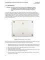
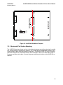
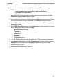
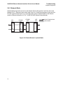
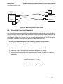
9145E10G Ethernet Network Interface Device User’s Manual
Maintenance
Check Optical Power Levels
5. If the reading is low, repeat the measurement with a different test cable. If the power level
is still not within range, call Canoga Perkins Technical Support.
FIBER OPTIC
TRANSMITTER
FIBER OPTIC
RECEIVER
-7dBm
λ = 1300 nm
OPTICAL
POWER
METER
Figure 6-1. Measuring Transmitter Output Power
6.2.2 Measuring Receiver Input Power
To measure receiver input power, follow these steps (seeFigure 6-2):
1. Connect the transmit fiber to the transmit side of the equipment at the local site.
2. Connect a calibrated optical power meter to the end of the transmit fiber at the remote
site.
3. Measure and record the optical power on the transmit fiber at the remote site. This is the
receiver input power for the transmit fiber from the local site.
4. Connect the transmit fiber to the transmit side of the equipment at the remote site.
5. Connect a calibrated optical power meter to the end of the transmit fiber at the local site.
6. Measure and record the optical power on the transmit fiber at the local site. This is the
receiver input power for the transmit fiber from the remote site.
7. Compare the receiver input power with the sensitivity level listed on the optical specifications sheet, located in the Client Support Area of the Canoga Perkins web site. The
power level must be within the sensitivity range listed on the data sheet. If not, contact
Canoga Perkins Technical Support.
8. Compare the receiver input power to the receiver’s saturation (overdrive) level shown on
the optical specifications sheet, located in the Client Support Area of the Canoga Perkins
web site. The power level must be lower than the saturation level. If not, contact Canoga
Perkins Technical Support.
38