1
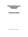
ORIENTAL MOTOR Co., Ltd.
Network converter
NETC02-CC
Sample Screen Manual
Mitsubishi Electric Corporation
Using the Samples
The sample screen data and files such as the instruction manual can be used upon agreement to the following
matters.
(1) This data is available for use by customers currently using or considering use of Mitsubishi
products.
(2) The intellectual property rights of the files provided by Mitsubishi (hereinafter referred to as the
“Files”) belong to Mitsubishi.
(3) Alteration, reproduction, transfer or sales of the Files is prohibited.
This does not apply when the content, in part or full, is used for Mitsubishi products incorporated
in a device or system created by the customer. Furthermore, this does not apply to the transfer,
reproduction, reference or change of layout in the specifications, designs or instruction manuals
of built-in products prepared by the customer using Mitsubishi products.
(4) Mitsubishi will not be held liable for any damages resulting from the use of the Files or the data
extracted from the Files. The customer is responsible for all use.
(5) If any usage conditions are appended to the Files, those conditions must be observed.
(6) The Files may be deleted or the contents changed without prior notice.
(7) When using the Files, please always read the corresponding manuals and related manuals
indicated therein. Please pay special attention to safety, and correctly handle the product.
2/76
BCN-P5999-0567
CONTENTS
REVISIONS ....................................................................................................................................................................5
1.
OUTLINE .................................................................................................................................................................6
2.
SYSTEM CONFIGURATION ..................................................................................................................................6
3.
GOT.........................................................................................................................................................................7
3.1
3.2
3.3
3.4
4.
CC-Link module (Q series)......................................................................................................................................8
4.1
4.2
5.
Network parameter setting for PLC engineering software...............................................................................8
Station information setting of network parameter ............................................................................................8
Network converter and driver ..................................................................................................................................9
5.1
5.2
5.3
5.4
6.
System Applications That Are Automatically Selected ....................................................................................7
Controller Setting of Screen Design Software .................................................................................................7
Ethernet Setting of Screen Design Software ...................................................................................................7
Overlap Window Setting of Screen Design Software ......................................................................................7
Communication Settings for the Network converter ........................................................................................9
Communication Settings for the AC power input driver ...................................................................................9
Communication Settings for the DC power input driver ..................................................................................9
Supported driver for the sample ......................................................................................................................9
SCREEN SPECIFICATIONS ............................................................................................................................... 10
6.1
Display Language ......................................................................................................................................... 10
6.2
Screen List/Transition ................................................................................................................................... 10
6.3
Explanation of Screens ................................................................................................................................. 15
6.3.1
AC/DC Selection Screen (B-30001) ..................................................................................................... 15
6.3.2
Menu (B-30002) .................................................................................................................................... 16
6.3.3
Operation data (B-31002) ..................................................................................................................... 17
6.3.4
Parameter Menu 1 (B-30003) ............................................................................................................... 19
6.3.5
Parameter I/O (B-31004) .................................................................................................................... 20
6.3.6
Parameter Motor (B-31005) ............................................................................................................... 21
6.3.7
Parameter Operation (B-31006) ......................................................................................................... 22
6.3.8
Parameter Return-to-home (B-31007) ............................................................................................... 23
6.3.9
Parameter Alarm & Warning (B-31008) ............................................................................................. 24
6.3.10
Parameter Menu 2 (B-30004) ............................................................................................................... 25
6.3.11
Parameter Coordinate (B-31010) ....................................................................................................... 26
6.3.12
Parameter Common (B-31011) .......................................................................................................... 27
6.3.13
Parameter I/O Function (B-31012) ..................................................................................................... 28
6.3.14
Parameter I/O Function RS-485 (B-31013)........................................................................................ 29
6.3.15
Parameter Communication (B-31014) ............................................................................................... 30
6.3.16
Monitor Menu (B-30005) ....................................................................................................................... 31
6.3.17
Monitor Status (B-31015) ................................................................................................................... 32
6.3.18
Monitor I/O Monitor (B-31016) ........................................................................................................... 33
6.3.19
Monitor Alarm Records (B-31018) ..................................................................................................... 34
6.3.20
Monitor Warning Records (B-31019).................................................................................................. 35
6.3.21
Manual Display (B-30500) .................................................................................................................... 36
6.3.22
Test Multiple Operation (B-31022 to 31025) ...................................................................................... 38
6.3.23
System Data management (B-31030) ................................................................................................ 40
6.3.24
Alarm Reset (W-30001) ........................................................................................................................ 41
6.3.25
Language Setting (W-30002) ................................................................................................................ 42
6.3.26
Clock Setting (W-30003) ....................................................................................................................... 43
6.3.27
Axis Switching (W-30004) ..................................................................................................................... 44
6.3.28
Reading dialog (W-30010) .................................................................................................................... 45
6.3.29
Writing dialog (W-30011)....................................................................................................................... 46
6.3.30
Read error dialog (W-30012) ................................................................................................................ 47
6.3.31
Write error dialog (W-30013) ................................................................................................................ 48
3/76
BCN-P5999-0567
6.3.32
Operation Data Input (W-32001)........................................................................................................... 49
6.3.33
STOP Input Action (W-32002)............................................................................................................... 50
6.3.34
Home-seeking Mode (W-32003) ........................................................................................................... 51
6.3.35
IN Input Function Selection (W-32004) ................................................................................................. 52
6.3.36
NET-IN Input Function Selection (W-32005) ........................................................................................ 53
6.3.37
OUT/NET-OUT Function Selection (W-32006) ..................................................................................... 54
6.4
Device List .................................................................................................................................................... 55
6.5
Comment List ............................................................................................................................................... 61
6.6
Script List ...................................................................................................................................................... 62
7.
MANUAL DISPLAY .............................................................................................................................................. 75
7.1
8.
Preparing Document Data for Manual Display ............................................................................................. 75
Others................................................................................................................................................................... 76
8.1
Ladder Program ............................................................................................................................................ 76
4/76
BCN-P5999-0567
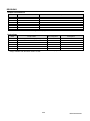
REVISIONS
Sample Screen Manual
Date
2015/7
Control No.*
BCN-P5999-0567
Description
First edition
* The Control No. is noted at the lower right of each page.
Project Data
Date
2015/7
Project data
GT Designer3*
ORIENTAL_NETC02-CC_V_Ver1_E.GTX
1.131M
Description
First edition
* The version number of screen design software used to create the project data is listed. Please use the screen
design software with the listed version or later.
5/76
BCN-P5999-0567
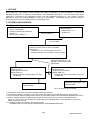
1. OUTLINE
This manual explains sample screens of GOT2000 connected to ORIENTAL MOTOR Co., Ltd. AR Series FLEX
driver (ARD-□D). The sample screen provides the system configuration in which GOT2000 is connected to
MELSEC-Q series PLC in Ethernet communication, and ORIENTAL MOTOR Co., Ltd. AR Series FLEX driver
(ARD-□D) is connected to the MELSEC-Q series PLC with ORIENTAL MOTOR Co., Ltd. network converter
NETC02-CC being connected therebetween in CC-Link communication. The sample screen is used to monitor or
change the current value and setting value of the stepping motor.
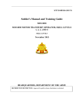
2. SYSTEM CONFIGURATION
2.1 System Configuration
GOT2000
・ GT27**-V(640×480)
・ Interface: Standard I/F (Ethernet)
・ SD card *1
・ Battery (GT11-50BAT) *2
<Master station>
・Q26UDVCPU *4 *5
・QJ61BT11N
Ethernet cable *3
CC-Link cable
ORIENTAL MOTOR Co., Ltd.
Network converter CC-Link Ver.2 compatible
NETC02-CC
・ Interface: CC-Link communication connector
・ Interface: RS-485 communication connector (CH6)
ORIENTAL MOTOR Co., Ltd.
RS-485 Communication cable
CC002-RS4
ORIENTAL MOTOR Co., Ltd.
AR Series FLEX
AC/DC power input driver
(Model: ARD-□D)
・ Interface: RS-485 communication connector
(CH6/CH7)
ORIENTAL MOTOR Co., Ltd.
AR Series FLEX
AC/DC power input driver
(Model: ARD-□D)
・ Interface: RS-485 communication connector
(CH6/CH7)
ORIENTAL MOTOR Co., Ltd.
Stepping Motor
ORIENTAL MOTOR Co., Ltd.
Stepping Motor
Up to 16 units can be connected.
*1: The SD card is used for the document display and recipe functions.
*2: The battery is used for the backup of the clock data. (The battery is provided with the GOT as standard.)
*3: For more details about the cable, please refer to the "GOT2000 Series Connection Manual (Mitsubishi Products)".
*4: Since the ladder program occupies a large portion of the program memory capacity, use Q26UDVCPU.
When you use the CPU whose capacity is smaller than that of Q26UDVCPU, select and limit the screen and
ladder program to be used.
*5: The ladder program is included in the following folder.
<Installation path for screen design software>¥GTD3_2000¥App¥SampleProject
6/76
BCN-P5999-0567
3. GOT
3.1 System Applications That Are Automatically Selected
Type
System application name
Standard Function
Standard System Application
Standard Font
Communication Driver
Ethernet Connection
Standard Font
Extended Function
Outline Font
Gothic
Japanese
Ethernet (MELSEC), Q17nNC, CRnD-700,
Gateway
Chinese (Simplified)
Alphanumeric/Kana
Japanese (Kanji)
Chinese (Simplified)
Document Display
3.2 Controller Setting of Screen Design Software
Detail Setting
Item
Set value
GOT NET No.
GOT Station No.
GOT Ethernet Setting
GOT Communication Port No.
Retry (Times)
Startup Time (Sec)
Timeout Time (Sec)
Delay Time (ms)
Remarks
1
1
Refer to table below
5001
3
3
3
0
GOT Ethernet Setting
Item
Set value
Remarks
Reflect GOT Ethernet setting in the GOT
GOT IP Address
Subnet Mask
Default Gateway
Peripheral S/W Communication Port No.
Transparent Port No.
Checked
192.168.3.18
255.255.255.0
0.0.0.0
5015
5014
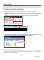
3.3 Ethernet Setting of Screen Design Software
1
Host
Net No.
Station
Unit Type
IP Address
Port No.
Communication
*
1
2
QnUD(P)V/QnUDEH
192.168.3.39
5006
UDP
3.4 Overlap Window Setting of Screen Design Software
[Close the window when switching base screens] of [Detail Setting] for overlap window in [Screen
Switching/Window] is enabled to close the window when switching base screens.
7/76
BCN-P5999-0567
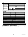
4. CC-Link module (Q series)
4.1 Network parameter setting for PLC engineering software
Item
No. of boards in module
Start I/O No.
Operation setting
Type
Mode setting
Total No. of connectable module
Remote input (RX)
Remote output (RY)
Remote register (RWr)
Remote register (RWw)
Special relay (SB)
Special register (SW)
Number of retries
Number of auto-replication
Standby master station No.
CPU down specification
Scan mode specification
Delay time setting
Station info setting
Remote device station initial setting
Interrupt setting
Set value
Remarks
1
0000H
Enable the cyclic data block
secure setting per station
Master station
Remote net Ver.2 mode
1
X1000
Y1000
W0
W1000
SB0
SW0
Default value
Refer to 4.2
Default value
4.2 Station information setting of network parameter
Item
Station type
Extended cyclic setting
Number of occupied station
Number of remote station
Reserved/Disable station specification
Set value
Remarks
Ver2. Remote device station
4-fold
4 stations
448 stations
No setting
8/76
BCN-P5999-0567
5. Network converter and driver
5.1 Communication Settings for the Network converter
When our company checks the controller, the set values are as follows.
(1) Settings for the dip switch and rotary switch of the network converter
Item
Set value
RS-485 communication connector
setting switch (N-AXIS)
CC-Link station number setting
switch (STATION No.)
CC-Link transmission baudrate
setting switch (B-RATE)
Function setting switch (SW4)
N-AXIS=1
STATION No.=1
B-RATE=4
No.2=ON
Remarks
Number of connector: 1
Station number: 1
10Mbps
Extended cyclic setting: 4-fold
5.2 Communication Settings for the AC power input driver
When our company checks the controller, the set values are as follows.
(1) Parameter settings
Item
Set value
Communication stop bit
Communication parity
1 bit
Even number
(2) DIP and rotary switch settings of the driver
Item
Set value
Address number setting switch(ID)
Transmission rate setting
switch(SW2)
Function setting switch(SW4)
Termination resistor setting
switch(TERM.)
Remarks
ID=0
SW2=7
No.1,No.2=OFF
No.1,No.2=OFF
Remarks
Change the value for each connected driver.
625000bps
OFF: Select the network converter
Only set termination resistor for the driver located
farthest away (positioned at the end) to on.
5.3 Communication Settings for the DC power input driver
When our company checks the controller, the set values are as follows.
(1) Parameter settings
Item
Set value
Communication stop bit
Communication parity
Remarks
1 bit
Even number
(2) DIP and rotary switch settings of the driver
Item
Set value
Address number setting switch(ID)
Transmission rate setting
switch(SW2)
Function setting switch(SW4)
Termination resistor setting
switch(TERM.)
ID=0
SW2=7
No.2=OFF
No.4=ON
Remarks
Change the value for each connected driver.
625000bps
OFF: Select the network converter
Only set termination resistor for the driver located
farthest away (positioned at the end) to on.
5.4 Supported driver for the sample
The sample can be used with the driver whose date of production or driver version meet the below conditions.
(1) The date of production
January 2014 or after
*The date of production is recorded on the driver plate.
(2) ド Driver version
AC power input driver : Ver.2.00 and later
DC power input driver : Ver.2.01 and later
*Driver version can be confirmed with the status and I/O monitor of the data setting software MEXE02.
9/76
BCN-P5999-0567
6. SCREEN SPECIFICATIONS
6.1 Display Language
The language of the text displayed on the screen can be switched between Japanese, English and Chinese
(Simplified). The text strings in each language are registered in the columns No.1 to No.3 in the comment groups
No.497 to No.500 as shown below. When the column No. is set in the language switching device, the language
corresponding to the column No. will appear.
Column No.
Language
1
2
3
English
Japanese
Chinese (Simplified)
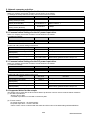
6.2 Screen List/Transition
6.2.1
Screen list/transition (common)
Window screen W-30003: Clock Setting
Window screen W-30002: Language Setting
System alarm
Window screen W-30004: Axis Switching
(Except for B-30001, B-31022 to 31025)
Base screen: All base screens
Window screen W-30001: Alarm Reset
10/76
BCN-P5999-0567
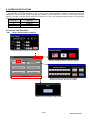
Window screen W-30010:
Reading dialog
Base screen: Operation data / Parameter /
Monitor (I/O) / Test Operation
Window screen W-30012:
Read error dialog
Window screen W-30011:
Writing dialog
Window screen W-30013:
Write error dialog
6.2.2
Screen list/transition (individual)
Base screen B-30001:
AC/DC selection screen
Base screen B-30002: Menu
Base screen B-31002:
Operation Data
Window screen W-32001:
Operation Data Input
To next
page
11/76
BCN-P5999-0567
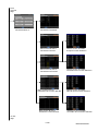
From
previous
page
Base screen B-30003:
Parameter Menu 1
Base screen B-31004:
Parameter I/O
Window screen W-32002:
STOP Input Action
Base screen B-31005:
Parameter Motor
Base screen B-31006:
Parameter Operation
Base screen B-31007:
Parameter Return-to-home
Window screen W-32003:
Home-seeking Mode
Base screen B-31008:
Parameter Alarm & Warning
To next
page
12/76
BCN-P5999-0567
From
previous
page
Base screen B-30004:
Parameter Menu 2
Base screen B-31010:
Parameter Coordinate
Base screen B-31011:
Parameter Common
Window screen W-32004:
IN Input Function Selection
Base screen B-31012:
Parameter I/O Function
Window screen W-32006:
OUT/NET-OUT Function Selection
Base screen B-31013:
Parameter I/O Function RS-485
Base screen B-31014:
Parameter Communication
Window screen W-32005:
NET-IN Input Function Selection
Window screen W-32006:
OUT/NET-OUT Function Selection
To next
page
13/76
BCN-P5999-0567
From
previous
page
Base screen B-30005:
Monitor Menu
Base screen B-31015:
Monitor Status
Base screen B-31016:
Monitor I/O Monitor
Base screen B-31022 to 31025:
Test Multi Operation
Base screen B-31030:
System Data Management
Base screen B-31018:
Monitor Alarm Records
Base screen B-31019:
Monitor Warning Records
Base screen B-30500:
Manual Display
14/76
BCN-P5999-0567
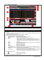
6.3 Explanation of Screens
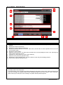
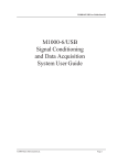
6.3.1
AC/DC Selection Screen (B-30001)
3
4
1
2
Outline
Select AC/DC power supply.
Description
1. Displays the address number of the driver to be monitored. The address number can be changed by
touching the numerical value.
2. Specifies the power supply type of the driver to be monitored.
3. Displays the current date and time. Touch the button to open the [Clock Setting] window.
4. Opens the [Language Setting] window.
Remarks
・ When GOT is started, the address number is set to “0” with the project script. For more details about
scripts, please refer to “6.6 Script List”.
・ If a system alarm occurs, the alarm message will appear at the bottom of the screen. When touching the left
end of the message, the display position of the message changes in the order of upper, center, and lower.
When touching the other part of the message, the [Alarm Reset] window appears.
15/76
BCN-P5999-0567
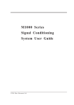
6.3.2
Menu (B-30002)
3
4
1
2
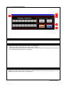
Outline
This is the Menu screen.
Description
1. Displays the address number of the driver to be monitored. Touch the button to open the [Axis Switching]
window.
2. Switches to each screen.
3. Displays the current date and time. Touch the button to open the [Clock Setting] window.
4. Opens the [Language Setting] window.
Remarks
・ If a system alarm occurs, the alarm message will appear at the bottom of the screen. When touching the
left end of the message, the display position of the message changes in the order of upper, center, and
lower. When touching the other part of the message, the [Alarm Reset] window appears.
16/76
BCN-P5999-0567
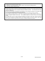
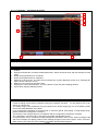
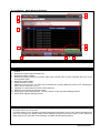
6.3.3
Operation data (B-31002)
9
10
1
6
5
2
3
4
7
8
Outline
This screen displays/changes the operation data of the driver and operates the stepping motor.
Description
1. Displays the address number of the driver to be monitored. Touch the button to open the [Axis Switching]
window.
2. Displays the operation data. Touch the operation data to open the [Operation data input] window and set
related operation data in the window.
3. Displays the command position and command speed of the motor.
4. Check the “Start teaching” to start teaching operation.
Minimum travel amount : Sets the minimum travel amount of motor.
Operation data No.
: Selects the operation data No.
: Moves forward/reverse while the button is touched.
These buttons accelerate or decelerate the operating speed of the
operation data No. which is selected among data No. 0 to data No. 7.
These buttons are disabled while the operation data No. except 0 to 7 is
selected.
: Adjusts the position of the motor. The travel amount of the motor equals to
the minimum travel amount.
Stop
: Stops the operating motor.
Alarm
: Displays the present alarm.
Alarm reset
: Resets the present alarm.
Positioning operation : Executes the positioning operation according to the operation data No.
Return-to-home operation : Starts the return-to-home operation
Set position
: Reflects the position of the motor to the position of the operation data No.
The operation mode will always be the absolute mode.
Position preset
: Sets the preset value to the command position. The preset value can be
changed in “Preset position” of the [Parameter Coordinate] screen.
5. Scrolls the operation data.
: Scrolls up one row of data.
6.
7.
: Scrolls down one row of data.
Updates the operation data to the latest data.
Switches to each screen. The blue switch indicates the currently displayed screen, thus selecting this
17/76
BCN-P5999-0567
switch will not switch the screen.
8. Switches to the previously opened screen.
9. Displays the current date and time. Touch the button to open the [Clock Setting] window.
10. Opens the [Language Setting] window.
Remarks
・ The project script is used to control the execution trigger for reading the monitored data. In addition, the
screen script is used to execute the automatic data reading at the time of the screen switching and to
control the dialog window which is displayed during the read/write operation. For the details on the script,
refer to "6.6 Script List".
・ During teaching operation, acceleration and deceleration can be changed according to the operation data
No. as long as acceleration/deceleration type is separate.
・ It is not possible to switch screen or change address number when executing teaching operation.
・ The set value of operation data No. 63 has been changed by using the ladder program to make the +/buttons to adjust the position of the motor. Thus, operation data No. 63 cannot be used on this sample
screen.
・ If a system alarm occurs, the alarm message will appear at the bottom of the screen. When touching the
left end of the message, the display position of the message changes in the order of upper, center, and
lower. When touching the other part of the message, the [Alarm Reset] window appears.
18/76
BCN-P5999-0567
6.3.4
Parameter Menu 1 (B-30003)
5
6
1
2
3
4
Outline
This is the Parameter menu 1.
Description
1. Displays the address number of the driver to be monitored. Touch the button to open the [Axis Switching]
window.
2. Switches to each screen.
3. Switches to each screen. The blue switch indicates the currently displayed screen, thus selecting this
switch will not switch the screen.
4. Switches to the previously opened screen.
5. Displays the current date and time. Touch the button to open the [Clock Setting] window.
6. Opens the [Language Setting] window.
Remarks
・ If a system alarm occurs, the alarm message will appear at the bottom of the screen. When touching the
left end of the message, the display position of the message changes in the order of upper, center, and
lower. When touching the other part of the message, the [Alarm Reset] window appears.
19/76
BCN-P5999-0567
6.3.5
Parameter I/O (B-31004)
7
8
1
4
3
2
5
6
Outline
This screen displays and edits the parameters of I/O.
Description
1. Displays the address number of the driver to be monitored. Touch the button to open the [Axis Switching]
window.
2. Displays and edits the I/O function related parameters. Yellow numerical value and text indicates a initial
value.
3. Reads all the parameters for I/O.
4. Writes all the parameters for I/O.
5. Switches to each screen. The blue switch indicates the currently displayed screen, thus selecting this
switch will not switch the screen.
6. Switches to the previously opened screen.
7. Displays the current date and time. Touch the button to open the [Clock Setting] window.
8. Opens the [Language Setting] window.
Remarks
・ The screen script is used to execute the automatic data reading at the time of the screen switching and to
control the dialog window which is displayed during the read/write operation. For the details on the script,
refer to "6.6 Script List".
・ The setting range of the parameters may vary based on the power supply type. For more details, please
refer to the USER MANUAL of the driver.
・ If you changed the parameters of LS logic level, HOMES logic level or SLIT logic level, please execute the
configuration command.
The function of the changed signal is not reflected until the configuration command is executed.
The configuration command can be executed in the [Data management] screen.
・ If a system alarm occurs, the alarm message will appear at the bottom of the screen. When touching the left
end of the message, the display position of the message changes in the order of upper, center, and lower.
When touching the other part of the message, the [Alarm Reset] window appears.
20/76
BCN-P5999-0567
6.3.6
Parameter Motor (B-31005)
7
8
1
4
3
2
5
6
Outline
This screen displays and edits the parameters of a motor.
Description
1. Displays the address number of the driver to be monitored. Touch the button to open the [Axis Switching]
window.
2. Displays and edits the motor related parameters. Yellow numerical value and text indicates a initial value.
3. Reads all the parameters for motor.
4. Writes all the parameters for motor.
5. Switches to each screen. The blue switch indicates the currently displayed screen, thus selecting this
switch will not switch the screen.
6. Switches to the previously opened screen.
7. Displays the current date and time. Touch the button to open the [Clock Setting] window.
8. Opens the [Language Setting] window.
Remarks
・ The screen script is used to execute the automatic data reading at the time of the screen switching and to
control the dialog window which is displayed during the read/write operation. For the details on the script,
refer to "6.6 Script List".
・ The setting range of the parameters may vary based on the power supply type. For more details, please
refer to the USER MANUAL of the driver.
・ If you changed the parameters of filter selection, control mode or smooth driver, please execute the
configuration command.
The function of the changed signal is not reflected until the configuration command is executed.
The configuration command can be executed in the [Data management] screen.
・ If a system alarm occurs, the alarm message will appear at the bottom of the screen. When touching the left
end of the message, the display position of the message changes in the order of upper, center, and lower.
When touching the other part of the message, the [Alarm Reset] window appears.
21/76
BCN-P5999-0567
6.3.7
Parameter Operation (B-31006)
7
8
1
4
3
2
5
6
Outline
This screen displays and edits the parameters of operation.
Description
1. Displays the address number of the driver to be monitored. Touch the button to open the [Axis Switching]
window.
2. Displays and edits the operation related parameters. Yellow numerical value and text indicates a initial
value.
3. Reads all the parameters for operation.
4. Writes all the parameters for operation.
5. Switches to each screen. The blue switch indicates the currently displayed screen, thus selecting this
switch will not switch the screen.
6. Switches to the previously opened screen.
7. Displays the current date and time. Touch the button to open the [Clock Setting] window.
8. Opens the [Language Setting] window.
Remarks
・ The screen script is used to execute the automatic data reading at the time of the screen switching and to
control the dialog window which is displayed during the read/write operation. For the details on the script,
refer to "6.6 Script List".
・ The setting range of the parameters may vary based on the power supply type. For more details, please
refer to the USER MANUAL of the driver.
・ If you changed the parameters of acceleration/deceleration unit or automatic return operation, please
execute the configuration command.
The function of the changed signal is not reflected until the configuration command is executed.
The configuration command can be executed in the [Data management] screen.
・ If a system alarm occurs, the alarm message will appear at the bottom of the screen. When touching the left
end of the message, the display position of the message changes in the order of upper, center, and lower.
When touching the other part of the message, the [Alarm Reset] window appears.
22/76
BCN-P5999-0567
6.3.8
Parameter Return-to-home (B-31007)
7
8
1
4
3
2
5
6
Outline
This screen displays and edits the parameters of Return-to-home.
Description
1. Displays the address number of the driver to be monitored. Touch the button to open the [Axis Switching]
window.
2. Displays and edits the return-to-home related parameters. Yellow numerical value and text indicates a
initial value.
3. Reads all the parameters for Return-to-home.
4. Writes all the parameters for Return-to-home.
5. Switches to each screen. The blue switch indicates the currently displayed screen, thus selecting this
switch will not switch the screen.
6. Switches to the previously opened screen.
7. Displays the current date and time. Touch the button to open the [Clock Setting] window.
8. Opens the [Language Setting] window.
Remarks
・ The screen script is used to execute the automatic data reading at the time of the screen switching and to
control the dialog window which is displayed during the read/write operation. For the details on the script,
refer to "6.6 Script List".
・ The setting range of the parameters may vary based on the power supply type. For more details, please
refer to the USER MANUAL of the driver.
・ If a system alarm occurs, the alarm message will appear at the bottom of the screen. When touching the left
end of the message, the display position of the message changes in the order of upper, center, and lower.
When touching the other part of the message, the [Alarm Reset] window appears.
23/76
BCN-P5999-0567
6.3.9
Parameter Alarm & Warning (B-31008)
7
8
1
4
3
2
5
6
Outline
This screen displays and edits the parameters of alarm & warning.
Description
1. Displays the address number of the driver to be monitored. Touch the button to open the [Axis Switching]
window.
2. Displays and edits the alarm and the warning related parameters. Yellow numerical value and text
indicates a initial value.
3. Reads all the parameters for alarm and warning.
4. Writes all the parameters for alarm and warning.
5. Switches to each screen. The blue switch indicates the currently displayed screen, thus selecting this
switch will not switch the screen.
6. Switches to the previously opened screen.
7. Displays the current date and time. Touch the button to open the [Clock Setting] window.
8. Opens the [Language Setting] window.
Remarks
・ The screen script is used to execute the automatic data reading at the time of the screen switching and to
control the dialog window which is displayed during the read/write operation. For the details on the script,
refer to "6.6 Script List".
・ The setting range of the parameters may vary based on the power supply type. For more details, please
refer to the USER MANUAL of the driver.
・ If you changed the parameters of Return-to-home incomplete alarm, please execute the configuration
command.
The function of the changed signal is not reflected until the configuration command is executed.
The configuration command can be executed in the [Data management] screen.
・ If a system alarm occurs, the alarm message will appear at the bottom of the screen. When touching the left
end of the message, the display position of the message changes in the order of upper, center, and lower.
When touching the other part of the message, the [Alarm Reset] window appears.
24/76
BCN-P5999-0567
6.3.10 Parameter Menu 2 (B-30004)
5
6
1
2
3
4
Outline
This is the parameter menu 2.
Description
1. Displays the address number of the driver to be monitored. Touch the button to open the [Axis Switching]
window.
2. Switches to each screen.
3. Switches to each screen. The blue switch indicates the currently displayed screen, thus selecting this
switch will not switch the screen.
4. Switches to the previously opened screen.
5. Displays the current date and time. Touch the button to open the [Clock Setting] window.
6. Opens the [Language Setting] window.
Remarks
・ If a system alarm occurs, the alarm message will appear at the bottom of the screen. When touching the
left end of the message, the display position of the message changes in the order of upper, center, and
lower. When touching the other part of the message, the [Alarm Reset] window appears.
25/76
BCN-P5999-0567
6.3.11 Parameter Coordinate (B-31010)
7
8
1
4
3
2
5
6
Outline
This screen displays and edits the parameters of the coordinate.
Description
1. Displays the address number of the driver to be monitored. Touch the button to open the [Axis Switching]
window.
2. Displays and edits the coordinate related parameters. Yellow numerical value and text indicates a initial
value.
3. Reads all the parameters for coordinate.
4. Writes all the parameters for coordinate.
5. Switches to each screen. The blue switch indicates the currently displayed screen, thus selecting this
switch will not switch the screen.
6. Switches to the previously opened screen.
7. Displays the current date and time. Touch the button to open the [Clock Setting] window.
8. Opens the [Language Setting] window.
Remarks
・ The screen script is used to execute the automatic data reading at the time of the screen switching and to
control the dialog window which is displayed during the read/write operation. For the details on the script,
refer to "6.6 Script List".
・ The setting range of the parameters may vary based on the power supply type. For more details, please
refer to the USER MANUAL of the driver.
・ If you changed the parameters of electronic gear A, electronic gear B, wrap setting, or wrap setting range,
please execute the configuration command.
The function of the changed signal is not reflected until the configuration command is executed.
The configuration command can be executed in the [Data management] screen.
・ If a system alarm occurs, the alarm message will appear at the bottom of the screen. When touching the left
end of the message, the display position of the message changes in the order of upper, center, and lower.
When touching the other part of the message, the [Alarm Reset] window appears.
26/76
BCN-P5999-0567
6.3.12 Parameter Common (B-31011)
7
8
1
4
3
2
5
6
Outline
This screen displays and edits the parameters of common.
Description
1. Displays the address number of the driver to be monitored. Touch the button to open the [Axis Switching]
window.
2. Displays and edits the common related parameters. Yellow numerical value and text indicates a initial
value.
3. Reads all the parameters for common.
4. Writes all the parameters for common.
5. Switches to each screen. The blue switch indicates the currently displayed screen, thus selecting this
switch will not switch the screen.
6. Switches to the previously opened screen.
7. Displays the current date and time. Touch the button to open the [Clock Setting] window.
8. Opens the [Language Setting] window.
Remarks
・ The screen script is used to execute the automatic data reading at the time of the screen switching and to
control the dialog window which is displayed during the read/write operation. For the details on the script,
refer to "6.6 Script List".
・ The setting range of the parameters may vary based on the power supply type. For more details, please
refer to the USER MANUAL of the driver.
・ If you changed the parameters of absolute backup system, please execute the configuration command.
The function of the changed signal is not reflected until the configuration command is executed.
The configuration command can be executed in the [Data management] screen.
・ If a system alarm occurs, the alarm message will appear at the bottom of the screen. When touching the left
end of the message, the display position of the message changes in the order of upper, center, and lower.
When touching the other part of the message, the [Alarm Reset] window appears.
27/76
BCN-P5999-0567
6.3.13 Parameter I/O Function (B-31012)
7
1
8
4
3
2
5
6
Outline
This screen displays and edits the parameters of I/O function.
Description
1. Displays the address number of the driver to be monitored. Touch the button to open the [Axis Switching]
window.
2. Displays and edits the I/O function related parameters. Yellow numerical value and text indicates a initial
value.
3. Reads all the parameters for I/O function.
4. Writes all the parameters for I/O function.
5. Switches to each screen. The blue switch indicates the currently displayed screen, thus selecting this
switch will not switch the screen.
6. Switches to the previously opened screen.
7. Displays the current date and time. Touch the button to open the [Clock Setting] window.
8. Opens the [Language Setting] window.
Remarks
・ The screen script is used to execute the automatic data reading at the time of the screen switching and to
control the dialog window which is displayed during the read/write operation. For the details on the script,
refer to "6.6 Script List".
・ The setting range of the parameters may vary based on the power supply type. For more details, please
refer to the USER MANUAL of the driver.
・ If you changed the parameters of I/O function, please execute the configuration command.
The function of the changed signal is not reflected until the configuration command is executed.
The configuration command can be executed in the [Data management] screen.
・ If a system alarm occurs, the alarm message will appear at the bottom of the screen. When touching the left
end of the message, the display position of the message changes in the order of upper, center, and lower.
When touching the other part of the message, the [Alarm Reset] window appears.
28/76
BCN-P5999-0567
6.3.14 Parameter I/O Function RS-485 (B-31013)
7
8
1
4
3
2
5
6
Outline
This screen displays and edits the parameters of I/O function RS-485.
Description
1. Displays the address number of the driver to be monitored. Touch the button to open the [Axis Switching]
window.
2. Displays and edits the I/O function RS-485 related parameters. Yellow numerical value and text indicates
a initial value.
3. Reads all the parameters for I/O function RS-485.
4. Writes all the parameters for I/O function RS-485.
5. Switches to each screen. The blue switch indicates the currently displayed screen, thus selecting this
switch will not switch the screen.
6. Switches to the previously opened screen.
7. Displays the current date and time. Touch the button to open the [Clock Setting] window.
8. Opens the [Language Setting] window.
Remarks
・ The screen script is used to execute the automatic data reading at the time of the screen switching and to
control the dialog window which is displayed during the read/write operation. For the details on the script,
refer to "6.6 Script List".
・ The setting range of the parameters may vary based on the power supply type. For more details, please
refer to the USER MANUAL of the driver.
・ If you changed the parameters of I/O function RS-485, please execute the configuration command.
The function of the changed signal is not reflected until the configuration command is executed.
The configuration command can be executed in the [Data management] screen.
・ If a system alarm occurs, the alarm message will appear at the bottom of the screen. When touching the left
end of the message, the display position of the message changes in the order of upper, center, and lower.
When touching the other part of the message, the [Alarm Reset] window appears.
29/76
BCN-P5999-0567
6.3.15 Parameter Communication (B-31014)
7
8
1
4
3
2
5
6
Outline
This screen displays and edits the parameters of communication.
Description
1. Displays the address number of the driver to be monitored. Touch the button to open the [Axis Switching]
window.
2. Displays and edits the communication related parameters. Yellow numerical value and text indicates a
initial value.
3. Reads all the parameters for communication.
4. Writes all the parameters for communication.
5. Switches to each screen. The blue switch indicates the currently displayed screen, thus selecting this
switch will not switch the screen.
6. Switches to the previously opened screen.
7. Displays the current date and time. Touch the button to open the [Clock Setting] window.
8. Opens the [Language Setting] window.
Remarks
・ The screen script is used to execute the automatic data reading at the time of the screen switching and to
control the dialog window which is displayed during the read/write operation. For the details on the script,
refer to "6.6 Script List".
・ The setting range of the parameters may vary based on the power supply type. For more details, please
refer to the USER MANUAL of the driver.
・ If a system alarm occurs, the alarm message will appear at the bottom of the screen. When touching the left
end of the message, the display position of the message changes in the order of upper, center, and lower.
When touching the other part of the message, the [Alarm Reset] window appears.
30/76
BCN-P5999-0567
6.3.16 Monitor Menu (B-30005)
5
6
1
2
3
4
Outline
This is the monitor menu.
Description
1. Displays the address number of the driver to be monitored. Touch the button to open the [Axis Switching]
window.
2. Switches to each screen.
3. Switches to each screen. The blue switch indicates the currently displayed screen, thus selecting this
switch will not switch the screen.
4. Switches to the previously opened screen.
5. Displays the current date and time. Touch the button to open the [Clock Setting] window.
6. Opens the [Language Setting] window.
Remarks
・ If a system alarm occurs, the alarm message will appear at the bottom of the screen. When touching the
left end of the message, the display position of the message changes in the order of upper, center, and
lower. When touching the other part of the message, the [Alarm Reset] window appears.
31/76
BCN-P5999-0567
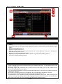
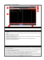
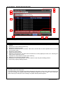
6.3.17 Monitor Status (B-31015)
9
10
1
2
3
4
5
6
7
8
Outline
This screen monitors the status of the motor.
Description
1. Displays the address number of the driver to be monitored. Touch the button to open the [Axis Switching]
window.
2. Displays the status of each item.
3. Displays the present alarm and warning.
4. Resets the absolute position error alarm. After reset, execute return-to-home operation and so on to set
home position again.
5. Resets the present alarm.
6. Switches to each screen. The blue switch indicates the currently displayed screen, thus selecting this
switch will not switch the screen.
7. Indicates an unused switch for base screen switching
8. Switches to the previously opened screen.
9. Displays the current date and time. Touch the button to open the [Clock Setting] window.
10. Opens the [Language Setting] window.
Remarks
・ The project script is used to control the execution trigger for reading the monitored data. For the details on
the script, refer to "6.6 Script List".
・ If a system alarm occurs, the alarm message will appear at the bottom of the screen. When touching the left
end of the message, the display position of the message changes in the order of upper, center, and lower.
When touching the other part of the message, the [Alarm Reset] window appears.
32/76
BCN-P5999-0567
6.3.18 Monitor I/O Monitor (B-31016)
8
9
1
3
2
4
5
6
7
Outline
This screen monitors I/O.
Description
1. Displays the address number of the driver to be monitored. Touch the button to open the [Axis Switching]
window.
2. Displays the status of INPUT.
3. Reads the function which is assigned to I/0.
4. Displays the status of OUTPUT.
5. Switches to each screen. The blue switch indicates the currently displayed screen, thus selecting this
switch will not switch the screen.
6. Indicates an unused switch for base screen switching
7. Switches to the previously opened screen.
8. Displays the current date and time. Touch the button to open the [Clock Setting] window.
9. Opens the [Language Setting] window.
Remarks
・ The project script is used to control the execution trigger for reading the monitored data. In addition, the
screen script is used to execute the automatic data reading at the time of the screen switching and to
control the dialog window which is displayed during the read/write operation. For the details on the script,
refer to "6.6 Script List".
・ If a system alarm occurs, the alarm message will appear at the bottom of the screen. When touching the left
end of the message, the display position of the message changes in the order of upper, center, and lower.
When touching the other part of the message, the [Alarm Reset] window appears.
33/76
BCN-P5999-0567
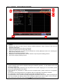
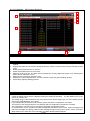
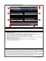
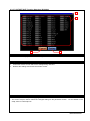
6.3.19 Monitor Alarm Records (B-31018)
10
11
1
2
3
5
4
6
7
8
9
Outline
This screen displays the alarm records.
Description
1. Displays the address number of the driver to be monitored. Touch the button to open the [Axis Switching]
window.
2. Displays the present alarm and warning.
3. Displays the alarm records.
4. Resets the absolute position error alarm. After reset, execute return-to-home operation and so on to set
home position again.
5. Resets the present alarm.
6. Clears the alarm records.
7. Switches to each screen. The blue switch indicates the currently displayed screen, thus selecting this
switch will not switch the screen.
8. Indicates an unused switch for base screen switching
9. Switches to the previously opened screen.
10. Displays the current date and time. Touch the button to open the [Clock Setting] window.
11. Opens the [Language Setting] window.
Remarks
・ The project script is used to control the execution trigger for reading the monitored data. For the details on
the script, refer to "6.6 Script List".
・ If a system alarm occurs, the alarm message will appear at the bottom of the screen. When touching the left
end of the message, the display position of the message changes in the order of upper, center, and lower.
When touching the other part of the message, the [Alarm Reset] window appears.
34/76
BCN-P5999-0567
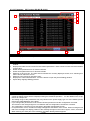
6.3.20 Monitor Warning Records (B-31019)
10
11
1
2
3
5
4
6
7
8
9
Outline
This screen displays the warning records.
Description
1. Displays the address number of the driver to be monitored. Touch the button to open the [Axis Switching]
window.
2. Displays the present alarm and warning.
3. Displays the warning records.
4. Resets the absolute position error alarm. After reset, execute return-to-home operation and so on to set
home position again.
5. Resets the present alarm.
6. Clears the warning records.
7. Switches to each screen. The blue switch indicates the currently displayed screen, thus selecting this
switch will not switch the screen.
8. Indicates an unused switch for base screen switching.
9. Switches to the previously opened screen.
10. Displays the current date and time. Touch the button to open the [Clock Setting] window.
11. Opens the [Language Setting] window.
Remarks
・ The project script is used to control the execution trigger for reading the monitored data. For the details on
the script, refer to "6.6 Script List".
・ If a system alarm occurs, the alarm message will appear at the bottom of the screen. When touching the left
end of the message, the display position of the message changes in the order of upper, center, and lower.
When touching the other part of the message, the [Alarm Reset] window appears.
35/76
BCN-P5999-0567
6.3.21 Manual Display (B-30500)
7
8
1
2
3
4
5
6
Outline
This screen displays the manual of the currently displayed language.
Description
1. Manual Display displays a document with document ID (201 to 203) according to the language. The page
1 is displayed when the screen is displayed initially. While touching the document, flicking to 8 directions
will scroll the document to 8 directions. While displaying the edge of the document, flicking the document
will switch pages. Pinching out and in will zoom in and out the document in 3 steps (large, middle, and
small).
2. Operates the displayed document.
: Enlarges or reduces the displayed document.
: Scrolls the displayed document to the left or right.
: Scrolls the displayed document up and down.
3. Operates the displayed document page.
: Displays the page number of the displayed document. Touch the value to change the page
number.
: Switches to the previous or next page of the displayed document.
4. Switches to each screen. The blue switch indicates the currently displayed screen, thus selecting this
switch will not switch the screen.
5. Indicates an unused switch for base screen switching.
6. Switches to the previously opened screen.
7. Displays the current date and time. Touch the button to open the [Clock Setting] window.
8. Opens the [Language Setting] window.
36/76
BCN-P5999-0567
Remarks
・ The language setting reflects documents for Manual display. The relation of the column No. of the comment
group No., languages and document (Document ID) is shown below.
Column No. of the comment
Language
Document ID
group No
1
English
201
2
Japanese
202
Chinese
3
203
(Simplified)
・ When GOT is started, the document page is set to No. “1” and the Document ID is set to "201" with the
project script. For more details about scripts, please refer to "6.6 Script List".
・ The page feed switches are set not to exceed the total number of document pages by object script. For
more details about scripts, please refer to “6.6 Script List”.
・ The document data for the manual display should be prepared by the customers. For more details, please
refer to "7. MANUAL DISPLAY".
・ If a system alarm occurs, the alarm message will appear at the bottom of the screen. When touching the left
end of the message, the display position of the message changes in the order of upper, center, and lower.
When touching the other part of the message, the [Alarm Reset] window appears.
37/76
BCN-P5999-0567
6.3.22 Test Multiple Operation (B-31022 to 31025)
7
8
1
2
4
3
5
6
Outline
This screen starts test operation for a multi axis motor.
Description
1. Select the Axis in execute test operation of the motor.
2. Touch the switch for each Axis can be test operation.
3. Displays the present alarm.
4. Executes the test operation for each Axis.
Data No.
: Selects the operation data No.
: Moves forward/ reverse continuously while the button is touched
continuously.
These buttons accelerate or decelerate the operating speed of the
operation data No. which is selected among data No. 0 to data No. 7.
These buttons are disabled while the operation data No. except 0 to 7 is
selected.
: Adjusts the position of the motor. The travel amount equals to the JOG
travel amount of the operation parameter.
Stop
: Stops the operating motor.
Positioning operation : Executes the positioning operation according to the operation data No.
Position preset
: Sets the preset value to the command position. The preset value can be
changed in “Preset position” of the [Parameter Coordinate] screen.
Return-to-home operation : Starts the Return-to-home operation.
Alarm reset
: Resets the present alarm.
5. Switches to each screen. The blue switch indicates the currently displayed screen, thus selecting this
switch will not switch the screen.
6. Switches to the previously opened screen.
7. Displays the current date and time. Touch the button to open the [Clock Setting] window.
8. Opens the [Language Setting] window.
38/76
BCN-P5999-0567
Remarks
・ The project script is used to control the execution trigger for reading the monitored data. In addition, the
screen script is used to notify the setting flag of the operation target axis to the PLC, to control the dialog
window which is displayed during the read/write operation, and to configure the interlock setting. For the
details on the script, refer to "6.6 Script List".
・ During test operation, acceleration and deceleration can be changed according to the operation data No. as
long as acceleration/deceleration type is separate.
・ It is not possible to switch screen or change address number when executing test operation.
・ The set value of operation data No. 63 has been changed by using the ladder program to make the +/buttons to adjust the position of the motor. Thus, operation data No. 63 cannot be used on this sample
screen.
・ If a system alarm occurs, the alarm message will appear at the bottom of the screen. When touching the left
end of the message, the display position of the message changes in the order of upper, center, and lower.
When touching the other part of the message, the [Alarm Reset] window appears.
39/76
BCN-P5999-0567
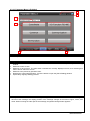
6.3.23 System Data management (B-31030)
8
1
9
2
4
3
5
6
7
Outline
This screen initializes the drivers, sets up Configuration and saves/reads the operation data and the
parameters.
Description
1. Displays the address number for which the data management is performed. Touch the button to open the
[Axis Switching] window.
2. Initializes all the operation data and parameters saved in the NV memory of the driver.
3. Executes a software reset. Some parameters are not reflected until a software reset is executed.
4. Saves the operation data and parameters from the RAM to the NV memory.
5. Reads the operation data and parameters from the NV memory to the RAM.
6. Switches to each screen. The blue switch indicates the currently displayed screen, thus selecting this
switch will not switch the screen.
7. Switches to the previously opened screen.
8. Displays the current date and time. Touch the button to open the [Clock Setting] window.
9. Opens the [Language Setting] window.
Remarks
・ Each switch works by pressing it for 2 seconds or more.
・ Each time configuration command starts or completes, momentarily loses the excitation of the motor.
Please pay extra attention when using vertical axis and so on. Moreover, the motor excites again after a
momentary cutoff, so a position deviation occurs. If position accuracy is required, it is recommended that
executing return-to-home operation immediately after configuration command is completed.
・ If a system alarm occurs, the alarm message will appear at the bottom of the screen. When touching the left
end of the message, the display position of the message changes in the order of upper, center, and lower.
When touching the other part of the message, the [Alarm Reset] window appears.
40/76
BCN-P5999-0567
6.3.24 Alarm Reset (W-30001)
2
1
Outline
This window screen allows resetting the system alarm.
Description
1. Resets the system alarm, and closes the window screen after 1 second.
2. Closes the window screen.
Remarks
41/76
BCN-P5999-0567
6.3.25 Language Setting (W-30002)
2
1
Outline
This window screen allows selecting the GOT language.
Description
1. Switches the language and closes the window screen.
2. Closes the window screen.
Remarks
・ The system language and Document ID for manual display also switched corresponding to the display
language.
42/76
BCN-P5999-0567
6.3.26 Clock Setting (W-30003)
4
1
2
3
Outline
This window screen allows changing the GOT clock data.
Description
1. Displays the current date and time.
2. Use
switches to change the date and time. Hold down the switches to increment or decrement the
value continuously. The [Reset] switch resets the seconds.
3. Applies the set date and time to the GOT clock data, and closes the window screen after 1 second.
4. Closes the window screen.
Remarks
・ The date and time at window opening are initially set as the clock data to be newly set.
・ Object scripts are set for the numerical display of the year, month, date, hour, minute and second in the
clock data to be newly set. For more details about scripts, please refer to “6.6 Script List”.
43/76
BCN-P5999-0567
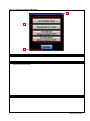
6.3.27 Axis Switching (W-30004)
3
1
2
3
4
Outline
Selects the address and the power supply type.
Description
1. Selects the address number of the driver to be monitored.
2. Specifies the power supply type of the driver to be monitored.
3. Closes the window screen without the settings being reflected.
4. Reflects the settings and closes the window screen. When the address number and power supply type
are not selected, the settings are not completed.
Remarks
・ The project script is used to execute the automatic parameter reading when the address number is
switched. A screen script is used for setting the address selection and the power supply type. For more
details about scripts, please refer to “6.6 Script List”.
44/76
BCN-P5999-0567
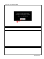
6.3.28 Reading dialog (W-30010)
Outline
This dialog window is displayed while the operation data or parameter is read.
Description
Remarks
45/76
BCN-P5999-0567
6.3.29 Writing dialog (W-30011)
Outline
This dialog window is displayed while the operation data or parameter is written.
Description
Remarks
46/76
BCN-P5999-0567
6.3.30 Read error dialog (W-30012)
1
Outline
This dialog window is displayed when an error has occurred while the operation data or parameter is read.
Description
1. Closes the window screen.
Remarks
47/76
BCN-P5999-0567
6.3.31 Write error dialog (W-30013)
1
Outline
This dialog window is displayed when an error has occurred while the operation data or parameter is written.
Description
1. Closes the window screen.
Remarks
48/76
BCN-P5999-0567
6.3.32 Operation Data Input (W-32001)
3
2
1
3
4
Outline
This window screen displays and edits the operation data.
Description
1. Displays and edits the operation data.
2. Numeric keypad to input.
3. Closes the window screen and the edited data is not reflected.
4. The edited data is reflected and closes the window screen.
Remarks
・ The screen script is used to initialize the input area of the operation data.
refer to "6.6 Script List".
49/76
For the details on the script,
BCN-P5999-0567
6.3.33 STOP Input Action (W-32002)
2
1
2
Outline
This window screen displays and sets the setting of STOP input action.
Description
1. Displays and sets the content of the STOP input action.
2. Closes the window screen.
Remarks
50/76
BCN-P5999-0567
6.3.34 Home-seeking Mode (W-32003)
2
1
2
Outline
This window screen displays and sets the setting of Home-seeking mode.
Description
1. Displays and sets the content of the Home-seeking mode.
2. Closes the window screen.
Remarks
51/76
BCN-P5999-0567
6.3.35 IN Input Function Selection (W-32004)
2
1
2
3
Outline
This window screen displays and sets the setting of IN input function selection.
Description
1. Displays and sets the content of the IN input function selection.
2. Closes the window screen without the settings being reflected.
3. Reflects the settings and closes the window screen.
Remarks
・ The screen script is used to reflect the changed settings to the parameter screen.
script, refer to "6.6 Script List".
52/76
For the details on the
BCN-P5999-0567
6.3.36 NET-IN Input Function Selection (W-32005)
2
1
2
3
Outline
This window screen displays and sets the setting of NET-IN input function selection.
Description
1. Displays and sets the content of the NET-IN input function selection.
2. Closes the window screen without the settings being reflected.
3. Reflects the settings and closes the window screen.
Remarks
・ The screen script is used to reflect the changed settings to the parameter screen.
script, refer to "6.6 Script List".
53/76
For the details on the
BCN-P5999-0567
6.3.37 OUT/NET-OUT Function Selection (W-32006)
2
1
2
3
Outline
This window screen displays and sets the setting of OUT/NET-OUT function selection.
Description
1. Displays and sets the content of the OUT/NET-OUT function selection.
2. Closes the window screen without the settings being reflected.
3. Reflects the settings and closes the window screen.
Remarks
・ MPS is only valid for AC power supply type.
・ The screen script is used to reflect the changed settings to the parameter screen.
script, refer to "6.6 Script List".
54/76
For the details on the
BCN-P5999-0567
6.4 Device List
Some of the devices specified to the on-screen switches and lamps, etc., are also used for common settings of
functions such as scripts. Using [Batch Edit] is recommended to change these devices in a batch. For more details
about using [Batch Edit], please refer to the "GT Designer3 (GOT2000) Help".
6.4.1
Devices of the controller
Type
Bit
Device No.
M1000
M1002
M1003
M1004
M1005
M1006
M1007
M1008
M1010
M1011
M1015
M1016
M1020
M1021
M1025
M1026
M1030
M1031
M1035
M1036
M1040
M1041
M1045
M1046
M1050
M1051
M1055
M1056
M1065
M1066
M1067
M1068
M1069
M1070
M1071
M1072
M1073
M1075
M1076
M1077
M1078
M1100
M1101
M1102
M1103
M1110
M1111
M1112
M1113
M1114
M1115
M1116
M1117
Application
Operation data read trigger
FB(DataRead) error detection device
FB(DataWrite) error detection device
Operation data screen test operation execution trigger
Operation data setting value change trigger
Minimum travel amount value write completion flag
Operation data screen Return-to-home operation execution trigger
Operation data screen set position execution trigger
I/O parameter read execution trigger
I/O parameter write execution trigger
Motor parameter read execution trigger
Motor parameter write execution trigger
Operation parameter read execution trigger
Operation parameter write execution trigger
Return-to-home parameter read execution trigger
Return-to-home parameter write execution trigger
Alarm & warning parameter read execution trigger
Alarm & warning parameter write execution trigger
Coordinate parameter read execution trigger
Coordinate parameter write execution trigger
Common parameter read execution trigger
Common parameter write execution trigger
I/O function parameter read execution trigger
I/O function parameter write execution trigger
I/O function RS-485 parameter read execution trigger
I/O function RS-485 parameter write execution trigger
Communication parameter read execution trigger
Communication parameter write execution trigger
Absolute position error alarm reset trigger
Alarm reset trigger
Record clear trigger
Alarm record clear flag
Warning record clear flag
Axis No. 00 – 03 Test operation flag
Axis No. 04 – 07 Test operation flag
Axis No. 08 – 11 Test operation flag
Axis No. 12 – 15 Test operation flag
Axis No. 00, 04, 08, 12 Test operation execution trigger
Axis No. 01, 05, 09, 13 Test operation execution trigger
Axis No. 02, 06, 10, 14 Test operation execution trigger
Axis No. 03, 07, 11, 15 Test operation execution trigger
Dialog window display flag
Read flag
Write flag
FB execution status reset trigger
Axis No. 00, 04, 08, 12 Continuous operation execution trigger
Axis No. 00, 04, 08, 12 Continuous operation reverse rotation flag
Axis No. 00, 04, 08, 12 Continuous operation forward rotation flag
Axis No. 00, 04, 08, 12 JOG operation execution trigger
Axis No. 00, 04, 08, 12 JOG operation reverse rotation flag
Axis No. 00, 04, 08, 12 JOG operation forward rotation flag
Axis No. 00, 04, 08, 12 Positioning operation execution trigger
Axis No. 00, 04, 08, 12 Position preset execution trigger
55/76
BCN-P5999-0567
Type
Bit
Device No.
M1118
M1119
M1120
M1121
M1122
M1123
M1124
M1125
M1126
M1127
M1128
M1129
M1130
M1131
M1132
M1133
M1134
M1135
M1136
M1137
M1138
M1139
M1140
M1141
M1142
M1143
M1144
M1145
M1146
M1147
M1148
M1149
M1150
M1151
M1152
M1153
M1200
M1201
M1202
M1203
M1204
M1205
M1206
M1210
M1220
M1230
M1231
M1235
M1236
M1237
M1238
M1240
M1241
M1242
M1243
M1244
D2546.b0
D2546.b1
D2546.b2
Application
Axis No. 00, 04, 08, 12 Return-to-home operation execution trigger
Axis No. 00, 04, 08, 12 Alarm reset execution trigger
Axis No. 01, 05, 09, 13 Continuous operation execution trigger
Axis No. 01, 05, 09, 13 Continuous operation reverse rotation flag
Axis No. 01, 05, 09, 13 Continuous operation forward rotation flag
Axis No. 01, 05, 09, 13 JOG operation execution trigger
Axis No. 01, 05, 09, 13 JOG operation reverse rotation flag
Axis No. 01, 05, 09, 13 JOG operation forward rotation flag
Axis No. 01, 05, 09, 13 Positioning operation execution trigger
Axis No. 01, 05, 09, 13 Position preset execution trigger
Axis No. 01, 05, 09, 13 Return-to-home operation execution trigger
Axis No. 01, 05, 09, 13 Alarm reset execution trigger
Axis No. 02, 06, 10, 14 Continuous operation execution trigger
Axis No. 02, 06, 10, 14 Continuous operation reverse rotation flag
Axis No. 02, 06, 10, 14 Continuous operation forward rotation flag
Axis No. 02, 06, 10, 14 JOG operation execution trigger
Axis No. 02, 06, 10, 14 JOG operation reverse rotation flag
Axis No. 02, 06, 10, 14 JOG operation forward rotation flag
Axis No. 02, 06, 10, 14 Positioning operation execution trigger
Axis No. 02, 06, 10, 14 Position preset execution trigger
Axis No. 02, 06, 10, 14 Return-to-home operation execution trigger
Axis No. 02, 06, 10, 14 Alarm reset execution trigger
Axis No. 03, 07, 11, 15 Continuous operation execution trigger
Axis No. 03, 07, 11, 15 Continuous operation reverse rotation flag
Axis No. 03, 07, 11, 15 Continuous operation forward rotation flag
Axis No. 03, 07, 11, 15 JOG operation execution trigger
Axis No. 03, 07, 11, 15 JOG operation reverse rotation flag
Axis No. 03, 07, 11, 15 JOG operation forward rotation flag
Axis No. 03, 07, 11, 15 Positioning operation execution trigger
Axis No. 03, 07, 11, 15 Position preset execution trigger
Axis No. 03, 07, 11, 15 Return-to-home operation execution trigger
Axis No. 03, 07, 11, 15 Alarm reset execution trigger
All data initialization trigger
Configuration execution trigger
Batch NV memory write trigger
Batch NV memory read trigger
Operation data screen positioning operation execution trigger
Operation data screen continuous operation execution trigger
Operation data screen continuous operation forward rotation flag
Operation data screen continuous operation reverse rotation flag
Operation data screen JOG operation execution trigger
Operation data screen JOG operation forward rotation flag
Operation data screen JOG operation reverse rotation flag
Operation data screen position preset execution trigger
Monitor FB execution command OFF notification
STOP command flag
Operation data screen
Axis No. 00, 04, 08, 12
Axis No. 01, 05, 09, 13
Axis No. 02, 06, 10, 14
Axis No. 03, 07, 11, 15
Operation data screen
Axis No. 00, 04, 08, 12
Axis No. 01, 05, 09, 13
Axis No. 02, 06, 10, 14
Axis No. 03, 07, 11, 15
STOP command trigger
STOP command trigger
STOP command trigger
STOP command trigger
STOP command trigger
Interlock during operation
Interlock during operation
Interlock during operation
Interlock during operation
Interlock during operation
I/O monitor + LS
I/O monitor – LS
I/O monitor HOMES
56/76
BCN-P5999-0567
Type
Bit
Word
Device No.
D2546.b3
D2546.b6
D2546.b7
D2546.b8
D2546.b9
D2546.b10
D2546.b11
D2546.b12
D2546.b13
D2547.b0
D2547.b1
D2547.b2
D2547.b3
D2547.b4
D2547.b5
D3862.b0
D3864.b0
D3884.b0
D3886.b0
D3888.b0
D3902.b0
D3924.b0
D3930.b0
D3932.b0
D3952.b0
D3954.b0
D3956.b0
D3980.b0
D3982.b0
D3984.b0
D3994.b0
D4014.b0
D4016.b0
D4024.b0
D4030.b0
D4032.b0
D4034.b0
D4056.b0
D4058.b0
D4060.b0
D4062.b0
D4064.b0
D4066.b0
D4068.b0
D4070.b0
D350
D800
D810
D812
D814
D816
D818
D820
D822
D824
D900
D901
D910
D920
D922
Application
I/O monitor SLIT
I/O monitor IN0
I/O monitor IN1
I/O monitor IN2
I/O monitor IN3
I/O monitor IN4
I/O monitor IN5
I/O monitor IN6
I/O monitor IN7
I/O monitor OUT0
I/O monitor OUT1
I/O monitor OUT2
I/O monitor OUT3
I/O monitor OUT4
I/O monitor OUT5
Hardware overtravel
Overtravel action
LS logic level
HOMES logic level
SLIT logic level
HOME-P output function selection
Filter selection
Control mode
Smooth driver
Acceleration/deceleration type
Acceleration/deceleration unit
Automatic return action
Starting direction of home-seeking
SLIT detection with home-seeking
TIM signal detection with home-seeking
Return-to-home incomplete alarm
Motor rotation direction
Software overtravel
Wrap setting
Data setter speed display
Data setter edit
Absolute-position backup system
IN0 input logic level setting
IN1 input logic level setting
IN2 input logic level setting
IN3 input logic level setting
IN4 input logic level setting
IN5 input logic level setting
IN6 input logic level setting
IN7 input logic level setting
Currently displayed base screen number notification device
Address number input
Axis No. 00, 04, 08, 12 Alarm
Axis No. 00, 04, 08, 12 Command position
Axis No. 01, 05, 09, 13 Alarm
Axis No. 01, 05, 09, 13 Command position
Axis No. 02, 06, 10, 14 Alarm
Axis No. 02, 06, 10, 14 Command position
Axis No. 03, 07, 11, 15 Alarm
Axis No. 03, 07, 11, 15 Command position
Offset value of the target input value (For word)
Offset value of the target input value (For double-word)
Operation data No. specification device for teaching operation
Axis No. 00 operation data No. specification device for teaching operation
Axis No. 01 operation data No. specification device for teaching operation
57/76
BCN-P5999-0567
Type
Device No.
Application
Word
D924
D926
D928
D930
D932
D934
D936
D938
D940
D942
D944
D946
D948
D950
D960
D1000+2n (n=0 to 62)
D1128+2n (n=0 to 62)
D1256+2n (n=0 to 62)
D1384+2n (n=0 to 62)
D1512+2n (n=0 to 62)
D1640+2n (n=0 to 62)
D1768+2n (n=0 to 62)
D1896+2n (n=0 to 62)
D2024+2n (n=0 to 62)
D2254
D2340+2n(n=0 to 7)
D2372+2n(n=0 to 5)
D2470
D2472+2n(n=0 to 9)
D2492
D2494+2n(n=0 to 9)
D2534
D2536
D2538
D2540
D2542
D2544
D2700+2n (n=0 to 62)
D2828+2n (n=0 to 62)
D2956+2n (n=0 to 62)
D3084+2n (n=0 to 62)
D3212+2n (n=0 to 62)
D3340+2n (n=0 to 62)
D3468+2n (n=0 to 62)
D3596+2n (n=0 to 62)
D3724+2n (n=0 to 62)
D3860
D3866
D3868
D3870
D3872
D3874
D3876
D3878
D3880
D3882
D3890
D3892
D3894
D3896
Axis No. 02 operation data No. specification device for teaching operation
Axis No. 03 operation data No. specification device for teaching operation
Axis No. 04 operation data No. specification device for teaching operation
Axis No. 05 operation data No. specification device for teaching operation
Axis No. 06 operation data No. specification device for teaching operation
Axis No. 07 operation data No. specification device for teaching operation
Axis No. 08 operation data No. specification device for teaching operation
Axis No. 09 operation data No. specification device for teaching operation
Axis No. 10 operation data No. specification device for teaching operation
Axis No. 11 operation data No. specification device for teaching operation
Axis No. 12 operation data No. specification device for teaching operation
Axis No. 13 operation data No. specification device for teaching operation
Axis No. 14 operation data No. specification device for teaching operation
Axis No. 15 operation data No. specification device for teaching operation
Alarm code storage device for operation data
Position No. 0 to No. 62
Operating speed No. 0 to No. 62
Operation mode No. 0 to No. 62
Operation function No. 0 to No. 62
Acceleration No. 0 to No. 62
Deceleration No. 0 to No. 62
Push current No. 0 to No. 62
Sequential positioning No. 0 to No. 62
Dwell time No. 0 to No. 62
Acceleration/deceleration unit
IN0 to IN7 input function selection
OUT0 to OUT5 input function selection
Current Alarm
Alarm history 1 to 10
Current warning
Warning history 1 to 10
Current selected data No.
Current operation data No.
Current position
Command speed
Feedback position
Feedback speed
Position No. 0 to No. 62 (For write operation)
Operating speed No. 0 to No. 62 (For write operation)
Operation mode No. 0 to No. 62 (For write operation)
Operation function No. 0 to No. 62 (For write operation)
Acceleration No. 0 to No. 62 (For write operation)
Deceleration No. 0 to No. 62 (For write operation)
Push current No. 0 to No. 62 (For write operation)
Sequential positioning No. 0 to No. 62 (For write operation)
Dwell time No. 0 to No. 62 (For write operation)
STOP input action (For write operation)
Positioning completion signal range (For write operation)
Positioning completion output offset (For write operation)
AREA1 positive direction position (For write operation)
AREA1 negative direction position (For write operation)
AREA2 positive direction position (For write operation)
AREA2 negative direction position (For write operation)
AREA3 positive direction position (For write operation)
AREA3 negative direction position (For write operation)
MOVE output minimum time (For write operation)
MS0 Operation No. selection (For write operation)
MS1 Operation No. selection (For write operation)
MS2 Operation No. selection (For write operation)
MS3 Operation No. selection (For write operation)
58/76
BCN-P5999-0567
Type
Word
Device No.
D3898
D3900
D3910
D3912
D3914
D3916
D3918
D3920
D3922
D3926
D3928
D3940
D3942
D3944
D3946
D3948
D3950
D3958
D3960
D3962
D3964
D3970
D3972
D3974
D3976
D3978
D3986
D3990
D3992
D3996
D3998
D4000
D4002
D4004
D4006
D4008
D4010
D4012
D4018
D4020
D4022
D4026
D4040+2n(n=0 to 7)
D4072+2n(n=0 to 5)
D4090+2n(n=0 to 15)
D4122+2n(n=0 to 15)
D4160
D4162
Application
MS4 Operation No. selection (For write operation)
MS5 Operation No. selection (For write operation)
RUN current (For write operation)
STOP current (For write operation)
Position loop gain (For write operation)
Speed loop gain (For write operation)
Speed loop integral time constant (For write operation)
Speed filter (For write operation)
Moving average time (For write operation)
Speed error gain 1 (For write operation)
Speed error gain 2 (For write operation)
Common acceleration (For write operation)
Common deceleration (For write operation)
Starting speed (For write operation)
JOG operating speed (For write operation)
JOG acceleration/deceleration (For write operation)
JOG starting speed (For write operation)
Automatic return operation speed (For write operation)
Automatic return acceleration/deceleration (For write operation)
Automatic return starting speed (For write operation)
JOG travel amount (For write operation)
Home-seeking mode (For write operation)
Operating speed of home-seeking (For write operation)
Acceleration/deceleration of home-seeking (For write operation)
Starting speed of home-seeking (For write operation)
Position offset of home-seeking (For write operation)
Operating current of push-motion home-seeking (For write operation)
Overload alarm (For write operation)
Overflow rotation alarm during current on (For write operation)
Overflow rotation alarm during current off (For write operation)
Overheat warning (For write operation)
Overload warning (For write operation)
Overspeed warning (For write operation)
Overvoltage warning (For write operation)
Undervoltage warning (For write operation)
Overflow rotation warning during current on (For write operation)
Electronic gear A (For write operation)
Electronic gear B (For write operation)
Positive software Limit (For write operation)
Negative software Limit (For write operation)
Preset position (For write operation)
Wrap setting range (For write operation)
IN0 to IN7 input function selection (For write operation)
OUT0 to OUT5 Output function selection (For write operation)
NET-IN0 to NET-IN15 input function selection (For write operation)
NET-OUT0 to NET-OUT15 input function selection (For write operation)
Communication timeout (For write operation)
Communication error alarm (For write operation)
59/76
BCN-P5999-0567
6.4.2
GOT internal devices
Type
Bit
Word
Device No.
GB40
GB60001
GB60002
GB61000
GB61001
GB61002
GB61010
GB61020
GB62000
GB62002
GB62004
GB62005
GB62006
GD60031.b13
GD60082.b15
GS512.b0
GD60000
GD60001
GD60004
GD60009
GD60021
GD60022
GD60031, GD60041
GD60042
GD60043
GD60080
GD60081
GD60082
GD60990
GD61001
GD61002
GD61011
GD61012
GD61015
GD61016
GD61018
GD61019
GD61021
GD61022
GD61024
GD61050
GD62500
GD63000
GD63001
GD63990 to GD63995
GS513 to GS516
GS650 to GS652
TMP950 to TMP996
Application
Always ON
Script trigger for storing the offset value of the position data
Screen switching interlock flag
Status flag
Address selection status flag
Power supply type status flag
Power supply type discrimination flag
Automatic Reading at Address Number Switching trigger
Input area initialization flag
Script trigger for determining the touch position
Write trigger of I/O function selection
OUT/NET-OUT discrimination bit
Overlap window displaying flag
Alarm reset
Maximum page number display flag
Time change signal
Base screen switching
Overlap window 1 screen switching
Overlap window 2 screen switching
Dialog window screen switching
Language switching
System language switching
System information
User ID indicated currently by cursor
Currently displayed base screen number
Document ID
Page No.
Last page No. notification device
Backup of currently displayed base screen number
Address number
Power supply type specification
Touch position storage device for operation data
Offset device for displaying operation data
Signal number of IN input
Temporary storage device for IN input function selection
Signal number of OUT output
Temporary storage device for OUT/NET-OUT output function
selection
Signal number of NET-IN input
Temporary storage device for NET-IN input function selection
Signal number of NET-OUT output
Address number comparison device
Offset value of position data
Address number of operation data input window
Offset device of operation data input window
Clock digiswitch
Change time
Present time
For script operation
60/76
BCN-P5999-0567
6.5 Comment List
Comment Group No.
Comment No.
497
498
499
No.1 to 240
No.1 to 60
No.1 to 90
No.1, 2
No.3
No.4
No.5
No.7
No.8
No.9 to 13
No.14 to 16, 18
No.17
No.19 to 20
No.22 to 23
No.25 to 26
No.27
No.28
No.29 to 31
No.32 to 33
No.34
No.36
No.37
No.38 to 40
No.50 to 51
No.100 to 132
No.150 to 187
No.200 to 220
No.250 to 271
No.300 to 318
No.350 to 364
No.400 to 415
No.450 to 459
No.500 to 526
No.550 to 584
No.600 to 604
No.650 to 660
No.700 to 703
No.800 to 806
No.850 to 856
No.1000 to 1014,
1031, 1046
No.1015 to 1018
No.1019 to 1022
No.1023 to 1026
No.1027 to 1030
No.1050 to 1064
No.1100 to 1101
No.1150
No.1200 to 1208
No.1250 to 1284
No.1300 to 1334
No.1350 to 1354
No.1400 to 1403
No.1450 to 1451
No.1500
No.1510
No.1520
No.1530
500
Where comments are used
B-31015, B-31018, B-31019
B-31012, B-31013, B-31016, W-32004, W-32005
B-31012, B-31013, B-31016, W-32006
B-30002 to B-30006, B-30500 to B-31030
B-30002, B-30003
B-30002, B-30004
B-30002, B-30005
B-30002
B-30001
B-30003, B-31004 to B-31008
B-30004, B-31010 to B-31014
B-30004
B-30005, B-30500, B-31015 to B-31019
B-30005
B-30006, B-31020 to B-31025
B-30003 to B-30006, B-31002, B-31010 to B-31014, B-31030
B-30003 to B-30006, B-31002 to B-31008, B-31030
B-30003 to B-30006, B-31002, B-31030
B-31004 to B-31008
B-31010 to B-31014
B-30003 to B-30005, B-30500 to B-31019, B-31030
B-30005, B-30500
B-30500, B-31015 to B-31019
B-30001 to B-30006, B-31002 to B-31019, B-31030
B-31002
B-31004
B-31005
B-31006
B-31007
B-31008
B-31010
B-31011
B-31012
B-31013
B-31014
B-31015
B-31016
B-31018
B-31019
B-31022 to B-31025
B-31022
B-31023
B-31024
B-31025
B-31030
W-30001
W-30002
W-30003
W-30004
W-32001
W-32002
W-32003
W-32004 to W-32006
W-30010
W-30011
W-30012
W-30013
61/76
BCN-P5999-0567
6.6 Script List
Item
Settings
Project script
Specified
Screen script
B-30500, B-31002 to B-31014, B-31016, B-31022 to B-31025, W-30004,
W-32001, W-32004 to W-32006
Object script
B-30500, W-30003
6.6.1
Project script
Script No.
30001
Script name
Comment
Initial setting
Data type
Signed BIN16
Trigger type
//Configure the initial setting
//The script is executed only once at the GOT startup.
Script30001
Rise GB40
[w:GD60080]=201; //Set Document ID to 201
[w:GD60081]=1; //Set Document page No. to 1
[w:D800] = 0;
// Initial value of Slave (driver) address number (number for Station No. switching)
[w:GD61050] = 0; //Initial value of address number comparison device
[w:GD61001] = 0xFF;
//Initial value of axis selection device of screen switching window
Script No.
30003
Script name
Script30003
Comment
Monitor flag control
Data type
Signed BIN16
Trigger type
Rise GB40
//Control the execution trigger for monitor FB for each base screen
//GD60043: Currently displayed base screen number
//GD60990: Backup of currently displayed base screen number
//M1220: Monitor FB execution command OFF notification
//D350: Currently displayed base screen number notification device
//When the currently displayed screen number is switched
if([u16:GD60990] != [u16:GD60043]) {
[u16:GD60990] = [u16:GD60043]; //Store the currently displayed base screen number into the backup
device
[w:D350] = [u16:GD60043]; //Notify the number of the currently displayed base screen to PLC
//Execute an individual processing according to the base screen number
switch([w:GD60043]){
case 31002:
//Base screen 31002 Operation data
rst([b:M1220]);
break;
case 31015:
//Base screen 31015 Monitor Status
rst([b:M1220]);
break;
case 31016:
//Base screen 31016 Monitor I/O monitor
rst([b:M1220]);
break;
case 31018:
//Base screen 31018 Monitor
Alarm records
rst([b:M1220]);
break;
case 31019:
//Base screen 31019 Monitor Warning records
rst([b:M1220]);
break;
default:
//Other screens
set([b:M1220]); //Monitor FB execution command OFF notification
break;
}
}
Script No.
30004
Script name
Script30004
Comment
AutoReading at address switching
Data type
Signed BIN16
Trigger type
ON GB61020
62/76
BCN-P5999-0567
//Read the parameter or other data on each screen when the address number is switched
//[w:GD61050]: Address number comparison device
//When the address number of the PLC device corresponds to that of the comparison device
if([w:GD61050] == [w:D800]){
//Set an individual read trigger according to the currently displayed screen number
switch([w:GD60043]){
case 31002:
set([b:M1000]); //Set the operation data read trigger
break;
case 31004:
set([b:M1010]); //Set the I/O parameter read trigger
break;
case 31005:
set([b:M1015]); //Set the motor parameter read trigger
break;
case 31006:
set([b:M1020]); //Set the operation parameter read trigger
break;
case 31007:
set([b:M1025]); //Set the Return-to-home parameter read trigger
break;
case 31008:
set([b:M1030]); //Set the alarm & warning parameter read trigger
break;
case 31010:
set([b:M1035]); //Set the coordinate parameter read trigger
break;
case 31011:
set([b:M1040]); //Set the common parameter read trigger
break;
case 31012:
set([b:M1045]); //Set the I/O function parameter read trigger
break;
case 31016:
set([b:M1045]); //Set the I/O function parameter read trigger
break;
case 31013:
set([b:M1050]); //Set the remote I/O parameter read trigger
break;
case 31014:
set([b:M1055]); //Set the communication parameter read trigger
break;
}
rst([b:GB61020]); //Terminate the activation trigger of the script.
}
Script No.
30103
Script name
Script30103
Comment
Close the dialog
Data type
Signed BIN16
Trigger type
OFF M1100
//Close the dialog window
[w:GD60009] = 0;
63/76
BCN-P5999-0567
6.6.2 Screen script
Base screen 30500
Script No.
30002
Script name
Script30002
Comment
DocumentDisplayProcessOfLastPage
Data type
Unsigned BIN16
Trigger type
Ordinary
//Check the total number of document pages is not 0.
if([w:GD60082]!=0){
//Compare the current page number to the total number of document pages to see if the current page number
exceeds the total number.
if([w:GD60081]>[w:GD60082]){
//Set the last page to display.
[w:GD60081]=[w:GD60082];
}
};
Base screen 31002
Script No.
30101
Script name
Comment
Automatic reading for operation data
Data type
Signed BIN16
Trigger type
//Execute the automatic data reading at the time of the screen switching
set([b:M1000]); //Turn ON the operation data read trigger
Script No.
30102
Script name
Comment
Dialog display
Data type
Signed BIN16
Trigger type
//Display the dialog window during the processing
//[b:M1002]: FB(DataRead) error detection device
//[b:M1003]: FB(DataWrite) error detection device
Script30101
Rise GB40
Script30102
ON M1100
//Display the dialog window while the operation data is read
if([b:M1101]){
//Switch the dialog window to be displayed according to the status of the error detection device
if([b:M1002]==OFF){
[w:GD60009] = 30010; //Display the reading dialog window
}else{
[w:GD60009] = 30012; //Display the reading error dialog window
}
}
//Display the dialog window while the operation data is written
if([b:M1102]){
//Switch the dialog window to be displayed according to the status of the error detection device
if([b:M1003] == 0){
[w:GD60009] = 30011; //Display the writing dialog window
}else{
[w:GD60009] = 30013; //Display the writing error dialog window
}
}
Script No.
30104
Script name
Script30104
Comment
OperationDataTouchPositionDetect
Data type
Signed BIN16
Trigger type
ON GB62002
//Calculate the input offset value based on the touch position of the operation data and the offset value of the
currently displayed operation No.
//GD61011: Touch position storage device for operation data
//GD61012: Offset device for displaying operation data
//Calculate the offset value based on the input value
[w:GD63000] = [w:GD61011] + (2 * [w:GD61012]);
64/76
BCN-P5999-0567
//Calculate the value of the selected operation data No.
[w:GD63001] = ([w:GD61011] /2) + [w:GD61012];
//Notify the input offset value to the PLC for the offset in units of double-word
[w:D901] = [w:GD63000];
//Notify the half value of the input offset value to the PLC for the offset in units of word
[w:D900] = [w:GD63000]/2;
[b:GB62002] = 0;
//Terminate the activation trigger of the script.
Script No.
30107
Script name
Script30107
Comment
Position data offset storage
Data type
Signed BIN16
Trigger type
ON GB60001
//Calculate the offset value to indicate the position data for teaching operation
//[w:GD62500]: Offset value of position data
//[w:D910]: Operation data No. specification device
//Calculate the offset value by using the two times value of the operation data since the position data is indicated
in units of double-word
[w:GD62500] = [w:D910] * 2;
Base screen 31004
Script No.
30110
Script name
Comment
Automatic reading for I/O parameter
Data type
Signed BIN16
Trigger type
//Execute the automatic data reading at the time of the screen switching
set([b:M1010]); //Turn ON the I/O parameter read trigger
Script No.
30102
Script name
Comment
Dialog display
Data type
Signed BIN16
Trigger type
Same as the script No. 30102 for the base screen 31002.
Script30110
Rise GB40
Script30102
ON M1100
Base screen 31005
Script No.
30115
Script name
Comment
Automatic reading for motor parameter
Data type
Signed BIN16
Trigger type
//Execute the automatic data reading at the time of the screen switching
set([b:M1015]); //Turn ON the motor parameter read trigger
Script No.
30102
Script name
Comment
Dialog display
Data type
Signed BIN16
Trigger type
Same as the script No. 30102 for the base screen 31002.
Script30115
Rise GB40
Script30102
ON M1100
Base screen 31006
Script No.
30120
Script name
Comment
Automatic reading for operation parameter
Data type
Signed BIN16
Trigger type
//Execute the automatic data reading at the time of the screen switching
set([b:M1020]); //Turn ON the operation parameter read trigger
Script No.
30102
Script name
Comment
Dialog display
Data type
Signed BIN16
Trigger type
Same as the script No. 30102 for the base screen 31002.
65/76
Script30120
Rise GB40
Script30102
ON M1100
BCN-P5999-0567
Base screen 31007
Script No.
30125
Script name
Script30125
Comment
Automatic reading for Return-to-home parameter
Data type
Signed BIN16
Trigger type
Rise GB40
//Execute the automatic data reading at the time of the screen switching
set([b:M1025]); //Turn ON the Return-to-home parameter read trigger
Script No.
30102
Script name
Comment
Dialog display
Data type
Signed BIN16
Trigger type
Same as the script No. 30102 for the base screen 31002.
Script30102
ON M1100
Base screen 31008
Script No.
30130
Script name
Comment
Automatic reading for alarm & warning
Data type
Signed BIN16
Trigger type
//Execute the automatic data reading at the time of the screen switching
set([b:M1030]); //Turn ON the alarm & warning parameter read trigger
Script No.
30102
Script name
Comment
Dialog display
Data type
Signed BIN16
Trigger type
Same as the script No. 30102 for the base screen 31002.
Script30130
Rise GB40
Script30102
ON M1100
Base screen 31010
Script No.
30135
Script name
Comment
Automatic reading for coordinate parameter
Data type
Signed BIN16
Trigger type
//Execute the automatic data reading at the time of the screen switching
set([b:M1035]); //Turn ON the coordinate parameter read trigger
Script No.
30102
Script name
Comment
Dialog display
Data type
Signed BIN16
Trigger type
Same as the script No. 30102 for the base screen 31002.
Script30135
Rise GB40
Script30102
ON M1100
Base screen 31011
Script No.
30140
Script name
Comment
Automatic reading for common parameter
Data type
Signed BIN16
Trigger type
//Execute the automatic data reading at the time of the screen switching
set([b:M1040]); //Turn ON the common parameter read trigger
Script No.
30102
Script name
Comment
Dialog display
Data type
Signed BIN16
Trigger type
Same as the script No. 30102 for the base screen 31002.
Script30140
Rise GB40
Script30102
ON M1100
Base screen 31012, 31016
Script No.
Comment
Data type
30145
Script name
Automatic reading for I/O function parameter
Signed BIN16
Trigger type
66/76
Script30145
Rise GB40
BCN-P5999-0567
//Execute the automatic data reading at the time of the screen switching
set([b:M1045]); //Turn ON the I/O function parameter read trigger
Script No.
30102
Script name
Comment
Dialog display
Data type
Signed BIN16
Trigger type
Same as the script No. 30102 for the base screen 31002.
Script30102
ON M1100
Base screen 31013
Script No.
30150
Script name
Comment
Automatic reading for remote I/O parameter
Data type
Signed BIN16
Trigger type
//Execute the automatic data reading at the time of the screen switching
set([b:M1050]); //Turn ON the remote I/O parameter read trigger
Script No.
30102
Script name
Comment
Dialog display
Data type
Signed BIN16
Trigger type
Same as the script No. 30102 for the base screen 31002.
Script30150
Rise GB40
Script30102
ON M1100
Base screen 31014
Script No.
30155
Script name
Script30155
Comment
Automatic reading for communication parameter
Data type
Signed BIN16
Trigger type
Rise GB40
//Execute the automatic data reading at the time of the screen switching
set([b:M1055]); //Turn ON the communication parameter read trigger
Script No.
30102
Script name
Comment
Dialog display
Data type
Signed BIN16
Trigger type
Same as the script No. 30102 for the base screen 31002.
Script30102
ON M1100
Base screen 31022
Script No.
30200
Comment
Operation target
Data type
Signed BIN16
//Switch the axis to be operated
Script name
Axis 00 - 03
Trigger type
//Switch the axis status between valid and invalid
set([b:M1070]); //Set axis No. 00 to 03 to be valid
rst([b:M1071]); //Set axis No. 04 to 07 to be invalid
rst([b:M1072]); //Set axis No. 08 to 11 to be invalid
rst([b:M1073]); //Set axis No. 12 to 15 to be invalid
Script No.
30102
Script name
Comment
Dialog display
Data type
Signed BIN16
Trigger type
Same as the script No. 30102 for the base screen 31002.
Script30200
Rise GB40
Script30102
ON M1100
Script No.
30201
Script name
Script30201
Comment
Interlock setting
Data type
Signed BIN16
Trigger type
Ordinary
//Set the interlock to prevent the screen switching during the test operation
//When at least any one of the axis executes the test operation
if([b:M1075] || [b:M1076] || [b:M1077] || [b:M1078]){
set([b:GB60002]); //Turn ON the interlock for screen switching
67/76
BCN-P5999-0567
}else{
rst([b:GB60002]);
}
//Turn OFF the interlock for screen switching
Base screen 31023
Script No.
30205
Comment
Operation target
Data type
Signed BIN16
//Switch the axis to be operated
Script name
Axis 04 - 07
Trigger type
//Switch the axis status between valid and invalid
rst([b:M1070]); //Set axis No. 00 to 03 to be invalid
set([b:M1071]); //Set axis No. 04 to 07 to be valid
rst([b:M1072]); //Set axis No. 08 to 11 to be invalid
rst([b:M1073]); //Set axis No. 12 to 15 to be invalid
Script No.
30102
Script name
Comment
Dialog display
Data type
Signed BIN16
Trigger type
Same as the script No. 30102 for the base screen 31002.
Script No.
30201
Script name
Comment
Interlock setting
Data type
Signed BIN16
Trigger type
Same as the script No. 30201 for the base screen 31022.
Script30205
Rise GB40
Script30102
ON M1100
Script30201
Ordinary
Base screen 31024
Script No.
30210
Comment
Operation target
Data type
Signed BIN16
//Switch the axis to be operated
Script name
Axis 08 - 11
Trigger type
//Switch the axis status between valid and invalid
rst([b:M1070]); //Set axis No. 00 to 03 to be invalid
rst([b:M1071]); //Set axis No. 04 to 07 to be invalid
set([b:M1072]); //Set axis No. 08 to 11 to be valid
rst([b:M1073]); //Set axis No. 12 to 15 to be invalid
Script No.
30102
Script name
Comment
Dialog display
Data type
Signed BIN16
Trigger type
Same as the script No. 30102 for the base screen 31002.
Script No.
30201
Script name
Comment
Interlock setting
Data type
Signed BIN16
Trigger type
Same as the script No. 30201 for the base screen 31022.
Script30210
Rise GB40
Script30102
ON M1100
Script30201
Ordinary
Base screen 31025
Script No.
30215
Comment
Operation target
Data type
Signed BIN16
//Switch the axis to be operated
Script name
Axis 12 -15
Trigger type
Script30215
Rise GB40
//Switch the axis status between valid and invalid
rst([b:M1070]); //Set axis No. 00 to 03 to be invalid
rst([b:M1071]); //Set axis No. 04 to 07 to be invalid
rst([b:M1072]); //Set axis No. 08 to 11 to be invalid
set([b:M1073]); //Set axis No. 12 to 15 to be valid
68/76
BCN-P5999-0567
Script No.
30102
Script name
Comment
Dialog display
Data type
Signed BIN16
Trigger type
Same as the script No. 30102 for the base screen 31002.
Script30102
Script No.
30201
Script name
Comment
Interlock setting
Data type
Signed BIN16
Trigger type
Same as the script No. 30201 for the base screen 31022.
Script30201
ON M1100
Ordinary
Window screen 30004
Script No.
30100
Script name
Comment
Axis switching
Data type
Unsigned BIN16
Trigger type
//Transfer the axis switching data to each device from dummy device
Script30100
When closing a screen
//When the setting switch is touched
if([b:GB61000] == ON){
//Transfer the data to the axis device from dummy device
[w:D800] = [w:GD61001];
[w:GD61050] = [w:GD61001];
//Switch the displayed settings of the parameter according to the power supply type
if([w:GD61002] == 1){
[b:GB61010] = OFF;
}
if([w:GD61002] == 2){
[b:GB61010] = ON;
}
//Set the Automatic Reading at Address Number Switching trigger
set([b:GB61020]);
}
//Reset the value stored in the axis switching window
[w:GD61001]=0xFF;
[w:GD61002]=0;
rst([b:GB61000]);
rst([b:GB61001]);
rst([b:GB61002]);
Window screen 32001
Script No.
30105
Script name
Script30105
Comment
Input area initialization
Data type
Signed BIN16
Trigger type
ON GB62000
//Initialize the input area by transferring the value stored in the reading area to the writing area when the
operation data input window is displayed
[w:D2700[w:GD63000]] = [w:D1000[w:GD63000]]; //Position
[w:D2828[w:GD63000]] = [w:D1128[w:GD63000]];
//Operating speed
[w:D2956[w:GD63000]] = [w:D1256[w:GD63000]];
//Operation mode
[w:D3084[w:GD63000]] = [w:D1384[w:GD63000]];
//Operation function
[w:D3212[w:GD63000]] = [w:D1512[w:GD63000]];
//Acceleration
[w:D3340[w:GD63000]] = [w:D1640[w:GD63000]];
//Deceleration
[w:D3468[w:GD63000]] = [w:D1768[w:GD63000]];
//Push current
[w:D3596[w:GD63000]] = [w:D1896[w:GD63000]]; //Sequential positioning
[w:D3724[w:GD63000]] = [w:D2024[w:GD63000]];
//Dwell time
//Terminate the activation trigger of the script.
69/76
BCN-P5999-0567
Window screen 32004
Script No.
30146
Script name
Comment
IN Data setting
Data type
Signed BIN16
Trigger type
// Write the data of IN input function selection to the driver
Script30146
ON GB62004
// [u16:GD61015]: Signal number of IN input
// [u32:GD61016]: Temporary device of IN input function selection
switch([u16:GD61015]){
case 0: [u32:D4040] = [u32:GD61016];
break;
case 1: [u32:D4042] = [u32:GD61016];
break;
case 2: [u32:D4044] = [u32:GD61016];
break;
case 3: [u32:D4046] = [u32:GD61016];
break;
case 4: [u32:D4048] = [u32:GD61016];
break;
case 5: [u32:D4050] = [u32:GD61016];
break;
case 6: [u32:D4052] = [u32:GD61016];
break;
case 7: [u32:D4054] = [u32:GD61016];
break;
}
// IN0 input function selection setting
// IN1 input function selection setting
// IN2 input function selection setting
// IN3 input function selection setting
// IN4 input function selection setting
// IN5 input function selection setting
// IN6 input function selection setting
// IN7 input function selection setting
[b:GB62004] = 0; //Terminate the activation trigger of the script.
[w:GD60004] = 0; //Terminate the overlap window
Window screen 32005
Script No.
30151
Script name
Comment
NET-IN Data setting
Data type
Signed BIN16
Trigger type
// Write the data of NET-IN input function selection to the driver
Script30151
ON GB62004
// [u16:GD61021]: Signal number of NET-IN input
// [u32:GD61022]: Temporary storage device for NET-IN input function selection
switch([u16:GD61021]){
case 0 : [u32:D4090] = [u32:GD61022];
break;
case 1 : [u32:D4092] = [u32:GD61022];
break;
case 2 : [u32:D4094] = [u32:GD61022];
break;
case 3 : [u32:D4096] = [u32:GD61022];
break;
case 4 : [u32:D4098] = [u32:GD61022];
break;
case 5 : [u32:D4100] = [u32:GD61022];
break;
case 6 : [u32:D4102] = [u32:GD61022];
break;
case 7 : [u32:D4104] = [u32:GD61022];
break;
case 8 : [u32:D4106] = [u32:GD61022];
break;
case 9 : [u32:D4108] = [u32:GD61022];
break;
case 10: [u32:D4110] = [u32:GD61022];
// NET-IN0 input function selection setting
// NET-IN1 input function selection setting
// NET-IN2 input function selection setting
// NET-IN3 input function selection setting
// NET-IN4 input function selection setting
// NET-IN5 input function selection setting
// NET-IN6 input function selection setting
// NET-IN7 input function selection setting
// NET-IN8 input function selection setting
// NET-IN9 input function selection setting
// NET-IN10 input function selection setting
70/76
BCN-P5999-0567
break;
case 11: [u32:D4112] = [u32:GD61022];
break;
case 12: [u32:D4114] = [u32:GD61022];
break;
case 13: [u32:D4116] = [u32:GD61022];
break;
case 14: [u32:D4118] = [u32:GD61022];
break;
case 15: [u32:D4120] = [u32:GD61022];
break;
// NET-IN11 input function selection setting
// NET-IN12 input function selection setting
// NET-IN13 input function selection setting
// NET-IN14 input function selection setting
// NET-IN15 input function selection setting
}
[b:GB62004] = 0; //Terminate the activation trigger of the script.
[w:GD60004] = 0; //Terminate the overlap window
Window screen 32005
Script No.
30147
Script name
Script30147
Comment
OUT/NET-OUT Data setting
Data type
Signed BIN16
Trigger type
ON GB62004
// Write the data of OUT/NET-OUT output function selection to the driver
// [b:GB62005]: Bit to distinguish between OUT and NET-OUT (1: OUT, 0: NET-OUT)
// [u16:GD61018]: Signal number of OUT output
// [u16:GD61024]: Signal number of NET-OUT output
// [u16:GD61019]: Temporary storage device for OUT/NET-OUT output function selection
if([b:GB62005] == 1){
// When OUT output function is selected
switch([u16:GD61018]){
case 0: [u32:D4072] = [u32:GD61019]; // OUT0 output function selection setting
break;
case 1: [u32:D4074] = [u32:GD61019];
// OUT1 output function selection setting
break;
case 2: [u32:D4076] = [u32:GD61019];
// OUT2 output function selection setting
break;
case 3: [u32:D4078] = [u32:GD61019];
// OUT3 output function selection setting
break;
case 4: [u32:D4080] = [u32:GD61019];
// OUT4 output function selection setting
break;
case 5: [u32:D4082] = [u32:GD61019];
// OUT5 output function selection setting
break;
}
} else {
// When NET-OUT output function is selected
switch([u16:GD61024]){
case 0 : [u32:D4122] = [u32:GD61019]; // NET-OUT0 output function selection setting
break;
case 1 : [u32:D4124] = [u32:GD61019]; // NET-OUT1 output function selection setting
break;
case 2 : [u32:D4126] = [u32:GD61019]; // NET-OUT2 output function selection setting
break;
case 3 : [u32:D4128] = [u32:GD61019]; // NET-OUT3 output function selection setting
break;
case 4 : [u32:D4130] = [u32:GD61019]; // NET-OUT4 output function selection setting
break;
case 5 : [u32:D4132] = [u32:GD61019]; // NET-OUT5 output function selection setting
break;
case 6 : [u32:D4134] = [u32:GD61019]; // NET-OUT6 output function selection setting
break;
case 7 : [u32:D4136] = [u32:GD61019]; // NET-OUT7 output function selection setting
break;
case 8 : [u32:D4138] = [u32:GD61019]; // NET-OUT8 output function selection setting
break;
case 9 : [u32:D4140] = [u32:GD61019]; // NET-OUT9 output function selection setting
71/76
BCN-P5999-0567
break;
case 10: [u32:D4142] = [u32:GD61019];
break;
case 11: [u32:D4144] = [u32:GD61019];
break;
case 12: [u32:D4146] = [u32:GD61019];
break;
case 13: [u32:D4148] = [u32:GD61019];
break;
case 14: [u32:D4150] = [u32:GD61019];
break;
case 15: [u32:D4152] = [u32:GD61019];
break;
}
// NET-OUT10 output function selection setting
// NET-OUT11 output function selection setting
// NET-OUT12 output function selection setting
// NET-OUT13 output function selection setting
// NET-OUT14 output function selection setting
// NET-OUT15 output function selection setting
}
[b:GB62004] = 0; //Terminate the activation trigger of the script.
[w:GD60004] = 0; //Terminate the overlap window
6.6.3 Object Script
Base screen 30500
Object
Switch
Object ID *1
Script user ID
1
Data type
Unsigned BIN16
Trigger type
//Prevents exceeding the total number of the document pages.
if([u16:GD60081] >= [u16:GD60082]){
[u16:GD60081] = [u16:GD60082] - 1;
}
20042
Device Writing
Window screen 30003
Object
Numerical Display
Object ID *1
10035
Script user ID
1
Data type
Unsigned BIN16
Trigger type
Rise GB40
//Obtain Today's Year & Month from Clock Data
[w:TMP950] = [w:GS650] & 0xF000; //Obtain Tenths Digit of "Last 2-Digits of Year" from Clock Data for Setting
[w:TMP960] = [w:TMP950] >> 12; //Decimal Alignment
[w:TMP968] = [w:TMP960] * 10;//BCD->BIN
[w:TMP951] = [w:GS650] & 0x0F00; //Obtain Ones Digit of "Last 2-Digits of Year" from Clock Data for Setting
[w:TMP961] = [w:TMP951] >> 8;//BCD->BIN
[w:TMP973] = 2000 + [w:TMP968] + [w:TMP961]; //Set Year to TMP973 as BIN
[w:GD63990] = [w:TMP973]; //Set Year
[w:TMP952] = [w:GS650] & 0x00F0; //Obtain Tenths Digit of Month from Clock Data for Setting
[w:TMP962] = [w:TMP952] >> 4; //Decimal Alignment
[w:TMP969] = [w:TMP962] * 10;//BCD->BIN
[w:TMP953] = [w:GS650] & 0x000F; //Obtain Ones Digit of Month from Clock Data for Setting
[w:TMP974] = [w:TMP969] + [w:TMP953]; //Set Month to TMP974 as BIN
[w:GD63991] = [w:TMP974]; //Set Month
[w:TMP954] = [w:GS651] & 0xF000; //Obtain Tenths Digit of "Last 2-Digits of Day" from Clock Data for Setting
[w:TMP963] = [w:TMP954] >> 12; //Decimal Alignment
[w:TMP970] = [w:TMP963] * 10;//BCD->BIN
[w:TMP955] = [w:GS651] & 0x0F00; //Obtain Ones Digit of "Last 2-Digits of Day" from Clock Data for Setting
[w:TMP964] = [w:TMP955] >> 8;//BCD->BIN
[w:TMP975] =[w:TMP970] + [w:TMP964]; //Set Day to TMP975 as BIN
[w:GD63992] = [w:TMP975]; //Set Day
[w:TMP956] = [w:GS651] & 0x00F0; //Obtain Tenths Digit of Hour from Clock Data for Setting
[w:TMP965] = [w:TMP956] >> 4; //Decimal Alignment
[w:TMP971] = [w:TMP965] * 10;//BCD->BIN
[w:TMP957] = [w:GS651] & 0x000F; //Obtain Ones Digit of Hour from Clock Data for Setting
[w:TMP976] = [w:TMP971] + [w:TMP957]; //Set Hour to TMP976 as BIN
[w:GD63993] = [w:TMP976]; //Set Hour
72/76
BCN-P5999-0567
[w:TMP958] = [w:GS652] & 0xF000; //Obtain Tenths Digit of "Last 2-Digits of Minute" from Clock Data for
Setting
[w:TMP966] = [w:TMP958] >> 12; //Decimal Alignment
[w:TMP972] = [w:TMP966] * 10;//BCD->BIN
[w:TMP959] = [w:GS652] & 0x0F00; //Obtain Ones Digit of "Last 2-Digits of Minute" from Clock Data for Setting
[w:TMP967] = [w:TMP959] >> 8;//BCD->BIN
[w:TMP977] =[w:TMP972] + [w:TMP967]; //Set Minute to TMP977 as BIN
[w:GD63994] = [w:TMP977]; //Set Minute
[w:TMP993] = [w:GS652] & 0x00F0; //Obtain Tenths Digit of Second from Clock Data for Setting
[w:TMP995] = [w:TMP993] >> 4; //Decimal Alignment
[w:TMP996] = [w:TMP995] * 10;//BCD->BIN
[w:TMP994] = [w:GS652] & 0x000F; //Obtain Ones Digit of Second from Clock Data for Setting
[w:TMP978] = [w:TMP996] + [w:TMP994]; //Set Second to TMP978 as BIN
[w:GD63995] = [w:TMP978]; //Set Second
Object
Numerical Display
Object ID *1
10036
Script user ID
2
Data type
Unsigned BIN16
Trigger type
Ordinary
//BIN -> BCD Conversion
[w:TMP979] = [w:GD63990] - 2000; //Last 2-Digits of Year
[w:TMP980] = (([w:TMP979] / 10) << 4) + ([w:TMP979] % 10); //Year BIN -> BCD
[w:TMP981] = (([w:GD63991] / 10) << 4) + ([w:GD63991] % 10); //Month BIN -> BCD
[w:TMP982] = (([w:GD63992] / 10) << 4) + ([w:GD63992] % 10); //Day BIN -> BCD
[w:TMP983] = (([w:GD63993] / 10) << 4) + ([w:GD63993] % 10); //Hour BIN -> BCD
[w:TMP984] = (([w:GD63994] / 10) << 4) + ([w:GD63994] % 10); //Minute BIN -> BCD
[w:TMP985] = (([w:GD63995] / 10) << 4) + ([w:GD63995] % 10); //Second BIN -> BCD
Object
Numerical Display
Object ID *1
10037
Script user ID
3
Data type
Unsigned BIN16
Trigger type
Ordinary
//Year & Month Setting
[w:GS513] = ([w:TMP980] << 8) + [w:TMP981]; //Set Year & Month to Change Time Device
Object
Numerical Display
Object ID *1
10032
Script user ID
4
Data type
Unsigned BIN16
Trigger type
Ordinary
//Date & Time Setting
[w:GS514] = ([w:TMP982] << 8) + [w:TMP983]; //Set Date & Time to Change Time Device
Object
Numerical Display
Object ID *1
10033
Script user ID
5
Data type
Unsigned BIN16
Trigger type
Ordinary
//Minute & Second Setting
[w:GS515] = ([w:TMP984] << 8) + [w:TMP985]; //Set Minute & Second to Change Time Device
Object
Numerical Display
Object ID *1
10034
Script user ID
6
Data type
Unsigned BIN16
Trigger type
Ordinary
//Day of Week Setting
[w:TMP986] = [w:GD63990];
[w:TMP987] = [w:GD63991];
[w:TMP988] = [w:GD63992];
//Year (BIN)
//Month (BIN)
//Day (BIN)
if(([w:TMP987] == 1) || ([w:TMP987] == 2)){ //Correction Processing to Calculate January and February as
13th/14th Month
[w:TMP986] =[w:TMP986] - 1; //Subtract 1 from Year
[w:TMP987] =[w:TMP987] + 12; //Add 12 to Month
}
[w:TMP989] = [w:TMP986]/4; //Create Items Required for Zeller's Congruence
73/76
BCN-P5999-0567
[w:TMP990] = [w:TMP986]/100; //Create Items Required for Zeller's Congruence
[w:TMP991] = [w:TMP986]/400; //Create Items Required for Zeller's Congruence
[w:TMP992] = (13*[w:TMP987]+8)/5; //Create Items Required for Zeller's Congruence
//Calculate Day of Week Using Zeller's Congruence and Set the Day to Change Time Device
[w:GS516] = ([w:TMP986]+[w:TMP989]-[w:TMP990]+[w:TMP991]+[w:TMP992]+[w:TMP988])%7;
*1 The Object ID might be changed when a screen is utilized.
74/76
BCN-P5999-0567
7. MANUAL DISPLAY
Manuals can be displayed using the document display function. For more details about the document display
function, please refer to the "GT Designer3 (GOT2000) Help". Please note that the document display function does
not support language switching. Therefore, in the sample screens, the language of document is switched by switching
the document (Document ID) specified for a display language.
7.1 Preparing Document Data for Manual Display
Example: Displaying a English manual (document) for Manual Display on the base screen B-30500
(1) Convert the manual (Word or Excel, etc.) to be displayed into the document data (JPEG file) that can be used
with the document display function by using Document Converter. Set the Document Converter's [Document ID]
to 201.
*For details of the relation between Document ID and Display language, please refer to the table below.
Document Converter's
Document ID
Column No. of the
comment group No
1
2
3
Language
Document ID
English
Japanese
Chinese (Simplified)
201
202
203
*Please use Document Converter 2.09k or later. The total number pages and pages switches cannot work
properly with 2.08 or older versions.
(2) The document data is generated in the 201 folder in the DOCIMG. Save the entire DOCIMG folder into the SD
card root directory without changing the folder configuration inside the DOCIMG folder.
Document ID
SD card folder configuration
Note: In case the total number of pages is 100 or more.
This sample is made with the assumption that the total number of pages is up to 99 pages. If it exceeds 99 pages,
please modify the format of numerical input (the number of "#") that displays the total number of pages and the
page number of the currently displayed page.
75/76
BCN-P5999-0567
8. Others
8.1 Ladder Program
This sample screen applies the ladder program which is created by using the FB for ORIENTAL MOTOR network
converter NETC02-CC. For the FB, the start I/O number of the CC-Link module which is mounted on the PLC and
the CC-Link station number of the network converter are specified. Furthermore, to control the STOP signal of
remote I/O, the remote output device is directly operated. Change the ladder program according to the system
configuration as appropriate.
(1)Start I/O No. of CC-Link module and CC-Link station No. of network converter
(2)STOP signal control of remote I/O
76/76
BCN-P5999-0567