1
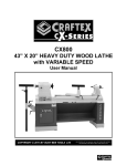
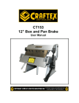
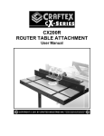
CX200S SLIDING TABLE ATTACHMENT FOR TABLE SAW User Manual GENERAL SAFETY INSTRUCTIONS FOR MACHINES Extreme caution should be used when operating all power tools. Know your power tool, be familiar with its operation, read through the user manual and practice safe usage procedures at all times. ALWAYS read and understand the user manual before operating the machine. CONNECT your machine ONLY to the matched and specific power source. ALWAYS wear safety glasses respirators, hearing protection and safety shoes, when operating your machine. DO NOT wear loose clothing or jewelry when operating your machine. A SAFE ENVIRONMENT is important. Keep the area free of dust, dirt and other debris in the immediate vicinity of your machine. BE ALERT! DO NOT use prescription or other drugs that may affect your ability or judgment to safely use your machine. DISCONNECT the power source when changing drill bits, hollow chisels, router bits, shaper heads, blades, knives or making other adjustments or repairs. NEVER leave a tool unattended while it is in operation. NEVER reach over the table when the tool is in operation. ALWAYS keep blades, knives and bits sharpened and properly aligned. ALL OPERATIONS MUST BE performed with the guards in place to ensure safety. ALWAYS use push sticks and feather boards to safely feed your work through the machine and clamp the work-piece (when necessary) to prevent the workpiece from any unexpected movement. ALWAYS make sure that any tools used for adjustments are removed before operating the machine. ALWAYS keep bystanders safely away while the machine is in operation. NEVER attempt to remove jammed cutoff pieces until the saw blade has come to a full stop. 2 UNPACKING ASSEMBLY The sliding table attachment is properly packaged and shipped completely in a box for safe transportation. When unpacking, carefully inspect and ensure that nothing has been damaged during transit. Open the box and check that the sliding table and the parts are in good condition. To install the sliding table attachment to the saw: Thread the foot pad into the support leg as shown in figure-2. Do not tighten the jam nut at this time. WARNING Before assembling the sliding table to your table saw, make sure the switch is in the “OFF” position and the power cord is disconnected from the power source. Failure to do so may cause serious personal injury or death. CONTENTS A. B. C. D. E. F. G. H. I. QTY Sliding Table ................................... Extension Table .............................. Fence Assembly.............................. Knurled Fence Handles................... Flip Stop .......................................... Lock Levers with T-Nuts.................. Support Legs................................... Feet ................................................. Mounting Screws & Washers .......... 1 1 1 2 1 2 2 2 3 Figure-2 Threading the foot pad into the bottom of the support leg Turn the sliding table upside down and slide the support leg T-nut into the sliding table miter gauge slot. Thread and secure the legs close to both ends of the sliding table. See figure-3. Figure-3 Attaching the support leg to the sliding table Figure-1 Inventory 3 Make sure the switch is in the OFF position and the cord is up-plugged from the power source. If there is an extension wing attached to the left side of the saw table, remove it. Get the help of an assistant or friend to turn the sliding table up right and hold it against the saw table. Pull out and rotate the locking pin located under the sliding table as shown in figure-4 and slide the top part of the table to access the mounting holes. IMPORTANT Before checking the sliding table parallelism with the blade, make sure that the saw blade is parallel to the main table miter slot. For details on adjustments please see your CX200 user manual page-22 To check if the sliding table is parallel to the blade, use an adjustable square and measure the distance between the miter slot on the sliding table and the edge of the blade (front or back). Mark that edge of the blade with a marker. Now, move the sliding table all the way to the rear of the table saw and rotate the blade with your hand, so that the marked point is opposite to the first position. (front or back) and slide the square to check if distance “A” is equals to distance “B”. Figure-4 Pulling out the locking pin Align the holes on the sliding table with the ones on the saw table and secure the sliding table to the saw table using three screws, washers and lock washers provided. See figure-4. Figure-6 Checking the sliding table T-slot parallelism with the saw blade Figure-5 Installing the sliding table 4 If the sliding table is not parallel with the saw blade, you will need to use masking tape on the mating surfaces of the tables (front or back) to make the sliding table parallel to the saw blade. Secure the fence by threading the knurled handles properly onto the T-bolts as shown in figure-9. Insert the extension table T-nuts through the T-slot on the outside edge of the sliding table. Attach the extension table to the sliding table as shown in figure-7 and secure it using lock levers provided. Figure-9 Installing the knurled handles Tighten the miter gauge lock knob shown in figure-9 to secure the miter gauge in place. Figure-7 Installing the extension table Remove the T-bolt from the bottom of one of the knurled handles and slide it into the T-slot on the sliding table as shown in figure-8. Insert the flip stop T-nut into the T-slot on the fence and secure the flip stop to the fence using the lock lever as shown in figure-10. Slide the miter gauge into the sliding table miter gauge slot and position the fence on sliding table with the knurled handle T-bolt and miter gauge T-bolt passing through the fence slot as shown in figure-8. Figure-10 Installing the flip stop A flip stop helps to make repetitive cuts of the same length and without adjusting the fence after each cut. Figure-8 Positioning the fence on the table 5 EXTENSION FENCE The extension fence provides support to cut long work-pieces. To position the extension fence, loosen the lock knob shown in figure-11 and pull the extension fence out as desired and retighten the lock knob. The fence can be set to various positions to accommodate different angles when performing different cutting. For Crosscutting When crosscutting, position the fence to the rear of the sliding table and set it to 90° to the blade and lock it in place. The extension table should be positioned just forward of the fence for maximum table support. Pull the extension fence out to provide more work-piece support (if needed). For Miter Cutting Figure-11 Extension fence POSITIONING THE FENCE The fence can be positioned anywhere on the sliding table at an angle between 50° right and 50° left. To position the fence: Make sure the switch is in the “OFF” position and the cord is un-plugged from the power source. Loosen the two knurled handles securing the fence to the table and the miter gauge lock knob. Take the fence to the desired position and desired angle. Re-tighten the knurled handles and the miter gauge lock knob to secure the fence in the desired angle. Position the fence to the rear of the sliding table and set the angle between 50° right and 50° left. Position the extension table to provide additional table support. Pull the extension fence out and position it to provide support for the work-piece. (if needed) Place the work-piece on the tables and hold it tightly against the fence. MAINTENANCE During the life of your sliding table, you will need to practice some regular maintenance to keep your sliding table in high performance condition. Clean the saw dust from the table surface and make sure there is no dust built up in the T-slots or around the table. Keep the cast iron surface free from rust. 6 SLIDING TABLE PARTS BREAKDOWN & LIST REF# QTY REF# 201 202 203 204 205 206 207 208 209 210 211 BUTTON HD SCREW M6-1*12 LOCK WASHER 6mm FLAT WASHER 6mm SLIDING TABLE SIDE COVER SLIDING TABLE ASSEMBLY CAR SCREW M8-1.25*25 LOCK WASHER 8mm FLAT WASHER 8mm FRONT TABLE SIDE COVER HEX BOLT M8-1.25*80 EXTENSION TABLE DESCRIPTION 8 2 8 2 1 3 5 5 1 2 1 213 214 215 216 217 218 219 220 221 222 223 212 T-NUT M8-1.25 4 DESCRIPTION LOCK LEVER M8-1.25 SUPPORT LEG HEX NUT M8-1.25 FOOT PAD LOCK LEVER FLAT WASHER 8mm STOP PLATE STOP PIN ASSEMBLY BUTTON HD CAP SCREW M5-.8 X LOCK WASHER 5mm FLAT WASHER 5mm REAR TABLE SIDE COVER QTY 2 2 4 2 2 1 1 4 4 4 1 7 FENCE PARTS BREAKDOWN 8 FENCE PARTS LIST REF# DESCRIPTION 101 KNURLED HANDLE M8-1.25 102 LONG CROSSCUT FENCE 103 KNOB BOLT M6-1 X 35 104 HANDLE SCREW M6-1 X 8 105 QTY REF# DESCRIPTION QTY 125 CAP SCREW M6-1 X 16 126 SET SCREW M6-1 X 8 127 FLIP STOP BRACKET 1 128 FLIP STOP PIVOT PIN 1 SQUARE NUT M5-.8 2 129 FLIP STOP 1 106 MITER GUAGE BODY 1 130 LOCK NUT M6-1 1 107 T-SLOT BLOCK 1 131 LOCK LEVER M6-1 X 32 1 108 LOCK WASHER 5MM 132 TEFLON FLAT WASHER 6MM 109 CAP SCREW M5-.8 X 20 133 SCALE MOUNTING PLATE 1 134 CROSSCUT FENCE EXTENSION BAR 1 135 PVC PAD 1 136 SCALE STRIP 137 MITER GUAGE STOP PIN 138 COMPRESSION SPRING 139 STOP PIN KNOB 3 140 SET SCREW M4-.7 X 8 1 1 141 BUTTON HD CAP SCR M4-.7 X 12 4 142 LOCK WASHER 4MM 143 FLAT WASHER 4MM 144 BUTTON HD CAP SCR M4-.7 X 8 2 1 1 2 2 2 1 1 1 110 STOP PIN BRACKET 111 MITER GUAGE T-SLOT BAR 112 MITER GUAGE PIVOT PIN 113 THREADED HANDLE BUSHING 114 TEFLON FLAT WASHER 8MM 115 T-BOLT M8-1.25 X 40 116 T-SLOT NUT M6-1 117 118 POINTER BRACKET KNOB BOLT M61 POINTER 119 LOCK WASHER 6MM 120 BUTTON HD CAP SCR M6-1 X 20 121 SHORT CROSSCUT FENCE 1 145 SPRING STRIP 2 122 SQUARE NUT M6-1 3 146 BUTTON HD CAP SCR M4-.7 X 12 1 123 CROSSCUT SUPPORT PLATE 147 FLAT WASHER 5MM 124 FLAT WASHER 6MM 148 POINTER 1 1 1 1 2 1 1 2 2 1 4 1 1 1 1 5 3 2 2 1 9 WARRANTY CRAFTEX 3 YEARS LIMITED WARRANTY Craftex warrants every product to be free from defects in materials and agrees to correct such defects where applicable. This warranty covers three years for parts and 90 days for labour (unless specified otherwise), to the original purchaser from the date of purchase but does not apply to malfunctions arising directly or indirectly from misuse, abuse, improper installation or assembly, negligence, accidents, repairs or alterations or lack of maintenance. Proof of purchase is necessary. All warranty claims are subject to inspection of such products or part thereof and Craftex reserves the right to inspect any returned item before a refund or replacement may be issued. This warranty shall not apply to consumable products such as blades, bits, belts, cutters, chisels, punches etceteras. Craftex shall in no event be liable for injuries, accidental or otherwise, death to persons or damage to property or for incidental contingent, special or consequential damages arising from the use of our products. RETURNS, REPAIRS AND REPLACEMENTS To return, repair, or replace a Craftex product, you must visit the appropriate Busy Bee Tools showroom or call 1800-461-BUSY. Craftex is a brand of equipment that is exclusive to Busy Bee Tools. For replacement parts directly from Busy Bee Tools, for this machine, please call 1-800-461-BUSY (2879), and have your credit card and part number handy. All returned merchandise will be subject to a minimum charge of 15% for re-stocking and handling with the following qualifications. Returns must be pre-authorized by us in writing. We do not accept collect shipments. Items returned for warranty purposes must be insured and shipped pre-paid to the nearest warehouse Returns must be accompanied with a copy of your original invoice as proof of purchase. Returns must be in an un-used condition and shipped in their original packaging a letter explaining your reason for the return. Incurred shipping and handling charges are not refundable. Busy Bee will repair or replace the item at our discretion and subject to our inspection. Repaired or replaced items will be returned to you pre-paid by our choice of carriers. Busy Bee reserves the right to refuse reimbursement or repairs or replacement if a third party without our prior authorization has carried out repairs to the item. Repairs made by Busy Bee are warranted for 30 days on parts and labour. Any unforeseen repair charges will be reported to you for acceptance prior to making the repairs. The Busy Bee Parts & Service Departments are fully equipped to do repairs on all products purchased from us with the exception of some products that require the return to their authorized repair depots. A Busy Bee representative will provide you with the necessary information to have this done. For faster service it is advisable to contact the nearest Busy Bee location for parts availability prior to bringing your product in for repairs. 10