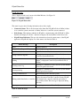
1
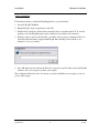
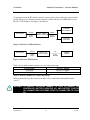
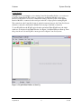
SEVCON PCpaK
User Manual - Version: 2.00.00 (UK0052)
Document History
Document History
Author
Reviewer
Initials
Date
Version
Reason for Modification
Initials
Date
CEH
27/09/01
1.0.0.21β
Original
CEH
05/10/01
UK0030
Added MillipaK Functionality
PS
06/11/01
UK0030
Changed MillipaK Functionality
PS
7/1/02
UK0049
Added Config ID Functionality
PS
8/2/02
UK0052
Added SEM flash prog and protocol select
PS
24/10/02
UK0052
Renamed PowerpaK SEM programmer
TSN
27/09/05
2.00.00
Revised for formal release
Contents
Contents
INTRODUCTION .............................................................................................................. 5
COMPATIBILITY.............................................................................................................. 5
IMPORTANT SAFETY NOTICE....................................................................................... 5
INSTALLATION ............................................................................................................... 6
System Requirements ................................................................................................................................................... 7
Software Installation..................................................................................................................................................... 8
Hardware Requirements .............................................................................................................................................. 9
Interface Modules..................................................................................................................................................... 10
Connection ............................................................................................................................................................... 11
FEATURES .................................................................................................................... 12
System Start Up........................................................................................................................................................... 13
Main Window .............................................................................................................................................................. 14
Node and Menu Item Panes ....................................................................................................................................... 16
Node and Node Menus (Left Hand-Pane) ................................................................................................................ 17
Menu Items (Right Hand-Pane) ............................................................................................................................... 18
PCpaK Menus ............................................................................................................................................................. 26
File Menu ................................................................................................................................................................. 27
Edit Menu................................................................................................................................................................. 32
View Menu............................................................................................................................................................... 33
Connection Menu ..................................................................................................................................................... 36
Log Menu ................................................................................................................................................................. 39
Tools Menu .............................................................................................................................................................. 41
Help Menu................................................................................................................................................................ 48
PCpaK Toolbar ........................................................................................................................................................... 49
PCpaK Language Selection........................................................................................................................................ 50
PCpaK Status Bar....................................................................................................................................................... 51
Controller System Profile Files .................................................................................................................................. 52
Flash Programming .................................................................................................................................................... 53
MillipaK ................................................................................................................................................................... 54
PowerpaK/MicropaK ............................................................................................................................................... 55
Notes about Flash Programming .............................................................................................................................. 56
PCpaK Manual
3
10/12/05
Contents
FAULT MESSAGES ...................................................................................................... 57
ORDERING INFORMATION .......................................................................................... 60
SOFTWARE UPDATES ................................................................................................. 60
CONTACT DETAILS...................................................................................................... 61
PCpaK Manual
4
10/12/05
Introduction
Introduction
PCpaK allows a PC to communicate with an individual controller or a controller system
comprising of more than one controller if they are inter-connected via a communications bus. The
software provides many advantages over using the standard calibrator hand set and offers the
following features:
Connection to multiple nodes where the nodes are connected to each other via a common bus.
Ability to save and load configurations to and from file.
Rapid download of system configurations.
Fault and service log analysis, where the controller system supports them.
Controller status checking.
View of controller structure.
“Offline” viewing of previously stored configurations.
Refer to controller product manual for details of controller features and programming options.
Compatibility
We are constantly updating our systems to allow PCpaK to interface to more of our controllers.
Refer to the appropriate Product Manual to determine if your Controller System is compatible
with PCpaK or contact SEVCON for a complete list of controllers which support PCpaK.
Important Safety Notice
WARNING: Care must be taken when operating using PCpaK on any system.
Changes to personalities can change vehicle performance and
operation. If the controller system is fitted to a vehicle ensure no
movement is possible before using PCpaK to make any changes.
WARNING: Do not connect your PC to a controller if the controller does not have
an adequate ground connected to B-. This is because the ground from
the controller follows through the serial port through the PC. You can
damage the PC if the controller pulls sufficient current (e.g. when
charging capacitors) and no other ground path is available.
PCpaK Manual
5
10/12/05
Installation
Installation
This section describes the steps necessary to install the PCpaK application and the recommended
system requirements (memory, disk space, etc.) required to operate it.
PCpaK Manual
6
10/12/05
Installation
System Requirements
System Requirements
System
A 486 machine is required as a minimum. A 266MHz Pentium with 64MB
of RAM is recommended.
Operating System
PCpaK will operate on Microsoft Windows 95/98/NT/2000/XP.
Storage
PCpaK is supplied via CD-ROM, therefore a CD-ROM drive is required.
PCpaK can be copied to a local hard disk drive or can be executed directly
from the CD-ROM. It is recommended that PCpaK is installed on a hard
disk, since the Cache function will not work if PCpaK is running from the
CD-ROM drive. PCpaK requires approximately 7MB of disk space.
Serial Port
PCpaK requires one free Serial Port capable of operating at 115KBaud.
Screen Resolution
Minimum resolution is 640 x 480 with 16 colours. 800 x 600 resolution is
recommended.
Table 1: System Requirements
PCpaK Manual
7
10/12/05
Installation
Software Installation
Software Installation
Follow this procedure to install the PCpaK application on your hard disk:
1. Insert the PCpaK CD-ROM.
2. Run the PCpaK_setup.exe application on the CD.
3. PCpaK will be installed to the hard disk, and will be able to run without the CD. To start the
program, select the PCpaK program option, which has been added to the start menu.
4. When the software runs for the first time, you will be asked to enter a configuration ID. You
should find this information supplied with PCpaK. Enter the ID provided exactly as it is
displayed – it is case sensitive.
5. Press OK when you have entered the ID. If it is accepted you will be taken to the main PCpaK
interface. If it is not accepted, you must enter it again.
The configuration ID only needs to be entered once. Once the ID has been accepted, you do not
need to enter it again.
PCpaK Manual
8
10/12/05
Installation
Hardware Connections
Hardware Requirements
This section explains how to connect up the system hardware to use PCpaK to communicate with
a Controller System.
PCpaK Manual
9
10/12/05
Installation
Hardware Connections - Interface Modules
Interface Modules
Connection between the PC and the controller systems must be done via the appropriate interface
module. There are two interface modules currently available, RS-232 to CANbus interface and
RS-232 to TTL interface. See Figure 1 and Figure 2.
PowerpaK
Traction Master
PC or Laptop
RS-232
9-way
D-type
RS-232 - CANbus
Interface Module
CANbus
6-way
MOLEX
PowerpaK
Pump Slave
Figure 1: RS-232 to CANbus Interface
PC or Laptop
RS-232
9-way
D-type
RS-232 - TTL
Interface Module
TTL
6-way
MOLEX
MillipaK
Controller
Figure 2: RS-232 to TTL Interface
Table 2 shows which interface module to use for each product range.
Product Range
PowerpaK
MillipaK
Interface Module
RS-232 to CANbus
RS-232 to TTL
Table 2: Interface Modules for each Product Range
Ordering information for these interface modules can be found in the Ordering Information
section.
WARNING: TO PREVENT POTENTIAL DAMAGE TO YOUR PC ENSURE THE
CONTROLLER BATTERY NEGATIVE (B-) AND BATTERY POSITIVE
(B+) CONNECTIONS ARE MADE PRIOR TO CONNECTING TO YOUR
PC.
PCpaK Manual
10
10/12/05
Installation
Hardware Connections - Connection
Connection
Once you have the appropriate interface module for your Product Range, you can connect up the
system as described below.
Interface Module to PC Connection
All interface modules have one 9-way D-type connector. This should be plugged into a free serial
port on your PC or laptop. The 6-way Molex connector should be plugged into the controller as
follows:
PowerpaK Controller System to Interface Module Connection
The PowerpaK range of controllers use a serial communications bus called CAN. CAN allows
many nodes to be easily connected together.
If your PowerpaK Controller System is setup to run in CANbus mode, then you only need to
connect the 6-way Molex connector from your module to any point on the CANbus to be able to
access all the nodes. The Interface Module is supplied with 2 Molex connectors, one male, and
one female. This is a straight through connection and is intended to be inserted into any point on
the CANbus.
Typically, if there is more than one node in a PowerpaK system it will be configured to run in
CANbus mode. This can be easily determined by checking if there is a wiring harness connecting
all the CANbus outputs on the controllers together. Refer to the appropriate Product Manuals for
your PowerpaK system for more information.
MillipaK Controller System to Interface Module Connection
The MillipaK range of controllers does not use CANbus and is not designed to communicate with
other nodes. The Serial Port is only used by the Calibrator or PCpaK.
If there is more than one MillipaK Controller on your vehicle, you will need to connect the 6-way
Molex connector from the Interface Module to the Serial Port of the controller you want to access
information from.
Protocol Selection
The 2 Interface Modules run using different protocols. Protocol selection is made in the PCpaK
options screen, which can be found in the tools menu. You must check you are using the correct
protocol; otherwise you will not be able to open communications.
PCpaK Manual
11
10/12/05
Features
Features
This section describes the features provided by PCpaK and gives instructions on how to operate
the program.
PCpaK Manual
12
10/12/05
Features
System Start Up
System Start Up
If PCpaK is to be used simply to view existing Controller System Profile files, (see section on
Controller System Profile Files) then no connection to an Interface Module is necessary.
However, if PCpaK is to be used to communicate with a Controller System, ensure that the
Interface Module is connected to the serial port on the PC or Laptop before starting PCpaK.
The connection to the Controller System is optional at start up; however, the Controller System
should be connected to the Interface Module before trying to establish a connection.
To start PCpaK select the PCpaK option from the start menu. When PCpaK starts, the initial
window to be displayed is the Main Window. See Figure 3 for Main Window at Start up. From
this point, the user can use PCpaK to interrogate and configure Controller Systems.
Figure 3: PCpaK Main Window at Start Up.
PCpaK Manual
13
10/12/05
Features
Main Window
Main Window
PCpaK has one main window, which is used to display all the information about a connected
controller system (if Online) or to display a previously saved Controller System Profile file (if
Offline).
Figure 4: PCpaK Main Window
This window uses a layout similar to Windows Explorer to allow the operator to edit personalities
and view controller system information.
The window is split into different panes, as shown in Figure 5. At the top of PCpaK's main
window, there is the standard Title Bar, Menu Bar and Toolbar. For further description of the
Menu Bar and Toolbar, refer to the PCpaK Menus and PCpaK Toolbar sections respectively.
PCpaK Manual
14
10/12/05
Features
Main Window
Title Bar
Menu Bar
X
Toolbar
Nodes and Menus
Menu Items
Language Selection
Status Bar
Figure 5: PCpaK Main Window Layout
The centre of the window is the main working area. The left hand pane is a Tree structure used to
display all the nodes in the controller system and the available menus for that node. The right
hand pane displays all the items for the selected menu. Refer to the Node and Menu Item Panes
section.
The bottom of the window contains the Language Selection drop down box and the Status Bar.
The Language Selection box is used to select the required language to display the menu
information in. The Language Selection box is described in the PCpaK Language Selection
section.
The Status Bar is used to show the current status of the system. For example, this shows if PCpaK
is connected to a controller (online) or not (offline). The Status Bar is described in the PCpaK
Status Bar section.
PCpaK Manual
15
10/12/05
Main Window
Nodes and Menu Item Panes
Node and Menu Item Panes
The two panes in the centre of the Main Window are used to show the Nodes and Node Menus
(left hand pane) and the menu items for the selected Node menu (right hand pane). Refer to Figure
4 and Figure 5.
The functions of the two panes are explained in the following sections.
PCpaK Manual
16
10/12/05
Main Window
Nodes and Menu Item Panes
Node and Node Menus (Left Hand-Pane)
The left hand pane uses a Tree structure to show all the Nodes in the system and the available
menus for each node. Note that menus may themselves have sub-menus. The Tree structure may
be expanded and collapsed as required by clicking on the '+' and '-' items. The Tree structure is
always fully expanded when a new connection is established.
Not all menus have data associated with them. Some menus (e.g. traction) are only displayed to
show sub menus. If a menu has no data associated with it, then it will be displayed with a red
icon. Other menus will appear with a green icon.
From the communications bus, all the nodes in the system are listed in numerical order. In
SEVCON systems node numbers are allocated according to the units function. Table 3 shows how
node numbers are allocated:
Node Number
0
1
2
3 onwards
Node Function
Master or Standalone Traction or
Combined Traction and Pump for Aerial Lift systems.
Slave Traction on Dual Motor Systems
Pump / Power Steer Controller
Reserved
Table 3: Node Number Allocation
Each node shows all of its sub-nodes (e.g. Traction or Pump or, in some cases, both) and each
sub-node shows all the menus and sub-menus it has available. On some systems, e.g. Aerial Lift
systems or MillipaKs with Pump Soft Start, both the Traction and Pump function can be
performed on the same node.
The user can select the Node or sub-Node items or an individual menu in the Tree structure to
display further information in the Menu Items pane (right hand pane). See the next section for
more information.
PCpaK Manual
17
10/12/05
Main Window
Nodes and Menu Item Panes
Menu Items (Right Hand-Pane)
The right hand pane displays information on a selected node, sub-node or menu using a table
format.
Node Items
Selecting a Node item in the left hand pane will display the information shown in Figure 6:
Figure 6: Node Information Screen
The information displayed here is:
Node Number. Node Number for the selected node.
Model. Description of the node, e.g. PowerpaK Traction Series or MillipaK Traction SEM.
Serial Number. Node serial number.
Protocol Version. Version of protocol used to communicate with node.
Software Version. Node software version.
Status. Status of node. This item will show if there is any fault currently active on the node.
Pers CRC. If the node supports this facility, the node personality CRC will be displayed here.
Refer to the product manual for more information.
PCpaK Manual
18
10/12/05
Main Window
Nodes and Menu Item Panes
Range Check. If any personalities are out of range, this item will show which one it is.
This information is read only and cannot be changed.
Sub-Node Items
Selecting a sub-Node item in the left hand pane may display the following information in the right
hand pane for some PowerpaK units. Note that whether or not this information is displayed
depends on the security level of the PCpaK installation and also the controller variant.
Configure. Node software version number and personality checksum.
Debug. Debug information for system development and analysis.
Figure 7: A Sub-Node Menu
This information is read only and cannot be changed. There is no sub-Node information displayed
for MillipaK systems.
PCpaK Manual
19
10/12/05
Main Window
Nodes and Menu Item Panes
Menu Items
Selecting a Menu item in the left hand pane will display information in the right hand pane
depending on the type of menu which is displayed. The different types of menus available are:
Configuration. Menus containing personality or setup information.
Status. Menus containing system status information and the service log.
Test. Menus containing system test information.
Faultlog. Faultlog menus.
Information. Any menus which do not fall into one of the above categories.
Note that the information in Status, Test, Faultlog and Information menus will only change if a
controller system is connected (i.e. Online). If PCpaK is in Offline mode, the information
displayed shows the last values received by PCpaK before it was disconnected.
Configuration Menus:
These menus display personality and setup menu items. See Figure 8.
Figure 8: A Configuration Menu
PCpaK Manual
20
10/12/05
Main Window
Nodes and Menu Item Panes
If the security level allows, the user can click on the value to be changed using the mouse and
modify the personality information using one of the following methods:
Two methods are available to change numerical information:
Simply type in the new value. Note that values will always be rounded to the nearest
allowed number.
When a configuration item is selected, '+' and '-' buttons appear at the right hand side of
the selected item. These '+' and '-' buttons can be used to increase and decrease the value.
Items which require the user to select an option provide a drop down list from which the user
can make their selection.
The following information is displayed for each menu item in a Configuration menu:
Value. The current value of the configuration item.
Min. The allowed minimum for the configuration. PCpaK will not allow the value to decrease
below this value. This field is blank for items which use drop down list boxes.
Max. The allowed maximum for the configuration. PCpaK will not allow the value to increase
above this value. This field is blank for items which use drop down list boxes.
Default. If the configuration item is shown as being out of range, this is the default value
which will be entered when the range error is first corrected.
Information. This provides further information about the menu item. For example, this
indicates if the value is out of range.
Information in Configuration menus can only be changed if a controller system is connected (i.e.
online). PCpaK will update the connected controller system with the new configuration item value
as soon as the user changes it and it has been validated.
Status Menus:
These display system status menu items. See Figure 9: A Status Menu.
These items are read only. Status menus also display service log information. The following
information is displayed for each menu item in a Status menu:
Current Value. The current value of the status item.
Highest Value. If the system supports a Service Log, a log is maintained of the highest value
seen for some status information. For example, PowerpaK systems log the highest Battery
Voltage. If logged, the highest value seen for the item is displayed in this field.
Lowest Value. If the system supports a Service Log, a log is maintained of the lowest value
seen for some status information. For example, PowerpaK systems log the lowest Heatsink
Temperature. If logged, the lowest value seen for the item is displayed in this field.
PCpaK Manual
21
10/12/05
Main Window
Nodes and Menu Item Panes
The information in Status menus will only change if a controller system is connected (i.e. online).
If PCpaK is in Offline mode, the information displayed shows the last values received by PCpaK
before it was disconnected from the controller system.
Figure 9: A Status Menu
PCpaK Manual
22
10/12/05
Main Window
Nodes and Menu Item Panes
Test Menus:
These display system test menu items. See Figure 10: A Test Menu.
Test menus are used to allow the user to check the systems inputs and outputs and also to provide
information on the unit. These items are read only. Only the current value is displayed for test
menu items. The Min, Max, Default and Information columns are not used.
The information in Test menus will only change if a controller system is connected (i.e. online). If
PCpaK is in Offline mode, the information displayed shows the last values received by PCpaK
before it was disconnected from the controller system.
Figure 10: A Test Menu
PCpaK Manual
23
10/12/05
Main Window
Nodes and Menu Item Panes
Faultlog Menus:
These display Faultlog menu items. See Figure 11.
Figure 11: A Faultlog Menu
These items are read only. Only PowerpaK systems support Faultlogs at present. The following
information is displayed for each menu item in a PowerpaK Faultlog menu:
Item. The flash fault group. Faults are grouped by flash fault group (e.g. 1FF, 3FF, etc) in the
PowerpaK Faultlog.
Last Fault Message. The last fault message displayed on the Calibrator for this flash fault
group.
Time. The Keyswitch hours when the last fault was logged.
Count. The number of faults logged in this flash fault since the last Faultlog reset.
Information Menus:
These display general information menu items. See Figure 12.
These items are read only. Only the current value is displayed for information menu items. The
Min, Max, Default and Information columns are not used.
PCpaK Manual
24
10/12/05
Main Window
Nodes and Menu Item Panes
Figure 12: An Information Menu
PCpaK Manual
25
10/12/05
PCpaK Menus
PCpaK Menus
This section explains the function of each of the Menu options in PCpaK.
PCpaK Manual
26
10/12/05
PCpaK Menus
File Menu
File Menu
The File Menu has the following options:
Open
Save
Print
Exit
Each menu item is explained more fully in the following sections.
PCpaK Manual
27
10/12/05
PCpaK Menus
File - Open
Open
This option allows the user to open an existing Controller System Profile file (*.sev). Refer to the
Controller System Profile Files section for more information about Controller System Profile
files.
A standard windows Open dialog box is displayed to allow the user to select the required file.
If PCpaK is not currently connected to a controller system, the System Profile file is opened as
read-only. It is not possible to make any changes, but all the information can be viewed.
If PCpaK is connected to a controller system, PCpaK will attempt to open the System Profile file
and update the connected system with the information contained within the Profile.
Before downloading the data, PCpaK will check that data stored in the System Profile is
compatible with the connected system. If the data is incompatible, an error will be displayed and
the file open is aborted. Once the data in the file has been downloaded, PCpaK will interrogate the
Controller System to read all the dynamic data. (i.e. Voltages, Currents, Faultlog information,
etc).
WARNING: If PCpaK is connected to a Controller System when a Controller
System Profile File is opened, it will automatically attempt to
download the data in the file to the Controller System. If this is not
required, ensure that the Controller System is disconnected before
the Controller System Profile File is opened.
PCpaK Manual
28
10/12/05
PCpaK Menus
File - Save
Save
This option allows the user to save the information from the connected controller system to a
Controller System Profile file (*.sev). Refer to the Controller System Profile Files section for
more information about Controller System Profile files.
A standard Windows Save dialog box is displayed to allow the user to name and save the System
Profile.
If PCpaK is not connected to a controller system, then this option is not available.
PCpaK Manual
29
10/12/05
PCpaK Menus
File - Print
Print
This option allows the user to print the displayed System Profile to a printer. Figure 13 shows the
Print Dialog Box.
Figure 13: Print Dialog Box
The Print Dialog Box allows the user to specify what is to be printed and also to include some
information about the User and the Controller System description onto the printed sheets.
If the Print Adjustable Values Only check box is not checked, PCpaK will:
Print all the information about the connected controller system, if Online, or
Print all the information in the Controller System Profile file, if Offline.
The printout will include all configuration information (personalities, setup items, etc) and the
information in the Status, Test, Faultlog and other Information menus.
If the Print Adjustable Values Only box is checked, PCpaK will only print the values of
configuration items (personalities, setup items, etc).
PCpaK always prints to the default printer.
PCpaK Manual
30
10/12/05
PCpaK Menus
File - Exit
Exit
This option allows the user to exit PCpaK.
PCpaK Manual
31
10/12/05
PCpaK Menus
Edit Menu
Edit Menu
This menu option is not yet available.
PCpaK Manual
32
10/12/05
PCpaK Menus
View Menu
View Menu
The View Menu has the following options:
Update Dynamic Data
Show / Hide Communication Status
Each menu item is explained more fully in the following sections.
PCpaK Manual
33
10/12/05
PCpaK Menus
View - Update Dynamic Data
Update Dynamic Data
This option allows the user to force a refresh of all the data currently displayed. Function key 'F5'
can be used to access this function.
PCpaK Manual
34
10/12/05
PCpaK Menus
View - Show / Hide Communication Status
Show / Hide Communication Status
The Communication Status dialog box (see Figure 14) shows when PCpaK is downloading and
uploading data to and from the controller system. This option can be used to hide or show this
dialog box.
Figure 14: Communication Status Dialog Box.
Function key 'F12' can also be used to show / hide the Communications Status dialog box.
PCpaK Manual
35
10/12/05
PCpaK Menus
Connection Menu
Connection Menu
The Connection Menu has the following options:
Open Connection.
Close Connection.
Each menu item is explained more fully in the following sections.
PCpaK Manual
36
10/12/05
PCpaK Menus
Connection - Open Connection
Open Connection
This option allows the user to connect PCpaK to a controller system. Function key 'F8' can also be
used to open a connection.
PCpaK will attempt to connect using the COM Port specified in the Options dialog box. Refer to
the Options section. Whilst the connection is established, PCpaK will display the Communication
Status dialog box. Refer to the Show / Hide Communication Status section.
The first step is to try to detect what controllers are present. On a multi-node system, where the
controllers are all connected via a common communications bus, PCpaK will attempt to detect all
the controllers on the bus. PCpaK will try to connect three times before aborting and displaying an
error message to the user.
If one or more controllers are found, PCpaK will upload all the information it requires and
displays the information in the Main Window.
PCpaK Manual
37
10/12/05
PCpaK Menus
Connection - Close Connection
Close Connection
This option allows the user to disconnect PCpaK from the Controller System. Function key 'F7'
can also be used to close the connection.
PCpaK Manual
38
10/12/05
PCpaK Menus
Log Menu
Log Menu
The Log Menu has the following options:
Clear Log
This menu item is explained more fully in the following section.
PCpaK Manual
39
10/12/05
PCpaK Menus
Log - Clear Log
Clear Log
This option only becomes available if the current item selected in the main window is a log which
can be reset. For example, on the PowerpaK range of controllers, resettable logs are the Fault Log
and Service Log. Refer to the product manual for the controller for a list of what logs are available
and which can be reset.
When the user has highlighted a resettable log and selects the Clear Log option, PCpaK sends a
command to the Controller System to reset the chosen log.
PCpaK Manual
40
10/12/05
PCpaK Menus
Tools
Tools Menu
The Tools Menu has the following options:
Rapid Download.
Flash Programming:
Options.
Each menu item is explained more fully in the following sections.
PCpaK Manual
41
10/12/05
PCpaK Menus
Tools - Rapid Download
Rapid Download
This option allows the user to download personality information to a controller system without
having to go through the connection procedure described in the previous section, Open
Connection. This feature is particularly useful when setting up a number of controller systems
with the same configuration.
The feature uses a Wizard to setup and perform the rapid download function. The steps are:
1. Choose Source and Destination Parameters. In this step, select the Controller System
Profile file which contains the system personalities to download. Click on Next when ready.
See Figure 15.
Figure 15: Rapid Download Wizard - Step 1.
2. Check Node Compatibility. On Multi-Node systems, it is possible to individually select or
de-select which nodes are to be updated. For example, on a Traction and Pump system it is
possible to request that both the nodes are updated or only the Traction Node or Pump Node is
updated.
In some exceptional circumstances, the user may have a system where the Destination Nodes
of the target Controller System are different to the Source Nodes defined in the Controller
System Profile file. PCpaK allows the user to map a source node to a different destination
node or to ignore a node altogether. The Dest Node column is used to change the destination
node. Setting the Dest Node to Ignore will exclude that node from the Rapid Download
updated. It is recommended that only advanced Users change destination nodes. In most
circumstances, the destination node should be identical to the source node.
By default, PCpaK will assume all nodes in the Controller System Profile file are to be
included in the Rapid Download and the destination node is the same as the source node.
After setting up the nodes as required, click Next. See Figure 16.
PCpaK Manual
42
10/12/05
PCpaK Menus
Tools - Rapid Download
Figure 16: Rapid Download Wizard - Step 2.
3. Download to Controllers. The system now has all the information it requires. Ensure that the
Controller System is connected to the PC and is powered up ready for the download. Click on
the Download button to download the information to the controllers. PCpaK will
automatically connect to the controllers, download the information, and then disconnect from
the controllers. Once this is complete, the user may plug their Interface Module into a new
controller system and repeat the download simply by clicking on Download again. This may
be performed as often as is necessary. The user may also if they wish choose to have the fault
or service logs reset after a rapid download operation. These logs will only be reset if rapid
download completes successfully. See Figure 17.
Figure 17: Rapid Download Wizard - Step 3.
PCpaK Manual
43
10/12/05
PCpaK Menus
Tools - Rapid Download
4. Finish. Once all the controller systems have been updated, click on Finish to return to the
main menu.
PCpaK Manual
44
10/12/05
PCpaK Menus
Tools - Options
Options
This option allows the user to configure PCpaK for their installation. When this menu item is
selected the following dialog box is displayed.
Figure 18: Options Dialog Box
This dialog is split into two sections:
COM Port and
Cache
See the sections, COM Port and Cache, below, for more information.
COM Port:
In this section, the operator can select the COM port. (e.g. COM1, COM2, etc).
Cache:
The first time PCpaK connects to a new controller system it must upload a lot of information
regarding menu structure, display formats, etc. This information is used to build up a map of the
controller system's menu structure.
For a specific controller type (e.g. PowerpaK Traction Series) and software version (e.g. V4.06)
the menu structure will never change. It is hard coded into the system's memory. Therefore, once
PCpaK has uploaded the structure information it does not need to upload it again.
PCpaK Manual
45
10/12/05
PCpaK Menus
Tools - Options
This section allows the user to specify if this structure information should be stored (or cached)
for future reference. The user has three options:
Cache Data
Refresh Data
Ignore Cache
If Cache Data is selected, PCpaK will check to see if it has uploaded data from this type of system
before. If it has, PCpaK only needs to upload dynamic data, such as personality values, status
information, etc. The menu structure information is already stored in a Cache file. This can greatly
improve the speed of the upload. If PCpaK has not uploaded data from this type of system before
it uploads all the information it requires, including structure information, and creates a cache file
for future reference.
If Refresh Data is selected, PCpaK will upload all the information from the controller system and
will create a fresh cache file, even if a file already exists. The old file is over-written.
If Ignore Cache is selected, PCpaK will always upload all the information from the controller
system, whether or not a Cache file exists for this setup. Also, a new Cache file is not created.
Protocol
Protocol selection allows PCpaK to communicate with a range of controllers.
•
Protocol 1 should be selected when using the RS232-CAN Interface Module when connecting
to CAN based controllers, such as PowerpaK or MicropaK.
•
Protocol 2 should be selected when using the RS232-TTL Interface Module when connecting
to TTL based controllers, such as MillipaK.
PCpaK Manual
46
10/12/05
PCpaK Menus
Tools - Options
Access Level allows you to choose the level of access to the controller menu structure. “Type 00”
gives access to standard controller menus and allows configuration of controller features. Other
types may be available, depending on your installation, to allow access to service and engineering
functions.
The write protect button may be ticked to prevent accidental modification of any setup or
personality values. It does however allow you to use rapid download, and to load a configuration
from file.
If you use PCpaK to write pre-set configurations to controllers, and want to be sure you don’t
accidentally change any settings, then we recommend this option is set.
Password Protection
The password protection option allows you to protect the options screen and prevent users from
modifying the configuration of PCpaK. This is particularly useful if you want to restrict the access
users have to controller functionality.
To set a password, check the “enable protection” box, and enter your chosen password into the
text box. You need to enter the password twice for confirmation. When the password is set you
will see a confirmation message. The next time you access the options dialog you will be
prompted for the password.
To remove password protection, clear the “enable protection” checkbox.
OK
Click the OK button to save settings. Clicking the OK button also saves the main window position
so it will return next time the program starts.
PCpaK Manual
47
10/12/05
PCpaK Menus
Help - About
Help Menu
The Help Menu has only the following option:
•
About
This displays a dialog box which gives information about this release of the PCpaK program. See
Figure 19.
The about dialog box displays the current version of PCpaK and the type of installation.
Figure 19: About Dialog Box
PCpaK Manual
48
10/12/05
PCpaK Toolbar
PCpaK Toolbar
This section describes the PCpaK Toolbar in more detail. See Figure 20. Each item in the toolbar
is a short cut for an existing menu item. The toolbar items are listed below and their
corresponding menu item in the PCpaK Menus section is shown. Refer to the appropriate menu
item section for more information.
Figure 20: PCpaK Toolbar
There are three items in the Toolbar. The Toolbar items from left to right are:
Open Connection. Refer to the Open Connection section. Shortcut key – f8.
Close Connection. Refer to the Close Connection section. Shortcut key – f7.
Open File. Opens a previously saved *.sev personality profile for loading into a controller or
for viewing offline.
Save Snapshot. Saves the current personality profile into a *.sev file.
Flash Program. Initiates flash programming dialog box depending on the controller protocol
selected (Protocol 1 for PowerpaK and MicropaK, and Protocol 2 for MillipaK).
Load Settings. Initiates Rapid Download dialog box (if offline), or opens a previously saved
personality profile (if connected).
Clear Log. Refer to the Clear Log section.
PCpaK Manual
49
10/12/05
PCpaK Language Selection
PCpaK Language Selection
PCpaK allows the user to select one of several languages in which to display all PCpaK menus,
dialog boxes and the controller system information. To change language selection, simply select
the required language from the Language Selection drop down list on the Main Window. PCpaK
will then update all displayed text appropriately for the new language.
New languages can easily be added without the need for changes to PCpaK. The language files
are stored as text files in the Languages sub-directory. There is one file per language. When it
starts up, PCpaK scans this directory and builds a list of the available language files. New
languages can be added simply by ensuring the required language file exists in this directory.
Contact SEVCON for a list of all supported languages.
If PCpaK detects an error in any language file other than the English one, then the text displayed
will default to the appropriate entry in the English Language file. If PCpaK detects an error in the
English language file, then PCpaK will do one of the following:
It will show the text as displayed on the Calibrator for controller system information on
PowerpaK systems or,
An Error Message will be displayed.
PCpaK Manual
50
10/12/05
PCpaK Status Bar
PCpaK Status Bar
This is displayed at the very bottom of the Main Window. See Figure 21.
Figure 21: PCpaK Status Bar
The status bar gives the following information (from left to right).
Connection Status. This is the first item in the Status Bar. PCpaK will show 'Offline' if there
is no controller system connected or 'Online' if there is a controller system connected.
Node Pointer. This indicates which node PCpaK is communicating with. If PCpaK is offline
then this will display 'No Nodes', otherwise it displays the node number of the active node.
PCpaK Status Indication. This provides information about the current status of the PCpaK
application. PCpaK will display one of the status codes listed in Table 4.
Status Message
Description
Ready
Normal operation.
MillipaK Flash Program Utility
Flash Programming utility is active.
Rapid download
Rapid Download utility is active.
Saving controller snapshot
Saving information on connected Controller System to
Controller System Profile file.
Printing
Printing information on connected Controller System, if
Online, or displayed Controller System Profile file, if
Offline.
Clearing service log
Waiting for confirmation from Controller System that the
Service Log has been cleared.
Clearing fault log
Waiting for confirmation from Controller System that the
Fault Log has been cleared.
Closing communications
Disconnecting from Controller System.
Writing cached data back to controller
If the user has changed a personality, then immediately
tried to disconnect from the Controller System, PCpaK
will maintain the connection until the personality is
successfully written. This message is displayed during
this time.
Opening communications
Attempting to connect to Controller System.
Table 4: Status Messages
PCpaK Manual
51
10/12/05
Features
Controller System Profile Files
Controller System Profile Files
The files used by PCpaK are called Controller System Profile Files. These files contain all the
information PCpaK requires about any Controller System.
When the user connects to a Controller System, PCpaK uploads all the information it requires
from the Controller System and displays it in the Main Window. This information includes
configuration items, such as personalities, and other information, such as status or test
information.
If the user selects the Save command from the File menu, a 'snapshot' of the current system is
saved to a System Profile file. This 'snapshot' contains all the information PCpaK has about the
system. This will include current personality values, status and test information, fault and service
log information, etc. This file can then be viewed later using PCpaK. This can be a useful tool for
recording the status of a system during development or whilst servicing a vehicle.
However, this 'snapshot' can also be used for a second purpose. The personalities are stored in the
file along with the other system information. These personalities can be extracted by PCpaK and
can be used to configure other identical systems. For example, for the Rapid Download, PCpaK
takes a System Profile file, extracts the personality information and downloads this to the
Controller System.
System Profile files can be used to either store a 'snapshot' of the current system for future
reference, or it can be used as a repository for a standard system configuration which can be
downloaded to other systems at a later date.
PCpaK Manual
52
10/12/05
Features
Controller System Profile Files
Flash Programming
Some Sevcon products are flash programmable, meaning that the software in the controller can be
upgraded to support new features or enhance the existing control system. Enhanced versions of
PCpaK allow the user to flash program a controller with new software by connecting the
controller to the PC using the Interface Module as normal.
If the controller is flash programmable then you can upgrade the software by connecting it to
PCpaK and selecting the flash programmer from the tools menu. If you do not see any flash
programmer options from the tools menu then you must contact Sevcon for an upgrade. Flash
programmer utilities are only available in enhanced versions of PCpaK.
The following sections explain how to flash new software into your controller.
PCpaK Manual
53
10/12/05
Features
Controller System Profile Files
MillipaK
Connection
The MillipaK can be flash programmed using the standard RS232-TTL Interface Module.
However, you must also connect the MillipaK Flash Programming Harness in-line to the 16-way
Molex connection on the controller. The vehicle light wiring that would normally be connected to
the 16-way Molex connection should now go through the harness. The controller needs to be
keyed on to be flash programmed.
Program Interface
Enter the software
filename here. Click the
… icon to browse for
the file.
Ensure the details
displayed here match
those provided by
Sevcon.
Click the “go” button to
start the flash
programming process.
To start the flash programmer, select Flash Programmer from the tools menu in PCpaK.
Start by entering the filename of the software in the filename field. This file will be in .s19 format.
You may browse for the file by clicking the … icon. When you have selected a file, you can
check the file information to verify the software integrity. The file size and timestamp allow you
to verify you have the correct file, and the checksum can be used to check the software file is not
corrupt. Sevcon publish file checksums with each version of software. The target controller type
informs the user what controller the software is for.
Clicking the go button starts the flash programming process.
Flash programming is done in two stages:
•
Stage 1 involves booting the controller and erasing the existing software from the controller.
You can monitor the progress of this stage on screen. Once the erase is complete the controller
must be restarted. PCpaK will prompt you to cycle the key switch when this happens.
•
At the start of stage 2 the controller contains no software. PCpaK will reboot the controller
and begin to download the new user software. Once this stage is complete the software will be
ready to run.
PCpaK Manual
54
10/12/05
Features
Controller System Profile Files
PowerpaK/MicropaK
Connection
Some PowerpaK/MicropaK controllers are flash programmable using the standard RS232-CAN
Interface Module. To flash program a controller, you must connect the PowerpaK flash
programming harness to socket A on the controller, and connect the Interface Module to the
harness. When the harness is connected to the controller, the controller will be ready to accept
new software from PCpaK. The controller must be keyed on to be flash programmed.
Program Interface
Enter the software
filename here. Click the
… icon to browse for
the file.
Ensure the details
displayed here match
those provided by the
software vendor.
Click the “go” button to
start the flash
programming process.
To start the PowerpaK/MicropaK flash programmer, select PowerpaK/MicropaK flash
programmer from the tools menu.
Enter the name of the software file, or click the … icon to browse. PowerpaK and MicropaK
software is supplied in binary format (.bin file). Once the file name has been entered the file
information will be displayed. This information should be checked against the information
provided by the Sevcon.
PowerpaK and MicropaK flash programming, unlike MillipaK flash programming, can be done in
one stage. To start flash programming, ensure the controller is keyed on. The LED on the
Interface Module should be on steady. Click the “go” button to start flash programming.
The status of the system will be displayed. When flash programming is complete you should
remove the flash programming harness. The controller should now be running the new software.
PCpaK Manual
55
10/12/05
Features
Controller System Profile Files
Notes about Flash Programming
•
When a flash programming harness is connected to a controller, all control functions
will be unavailable and drive is inhibited. This is normal operation.
•
You should always use the file information displayed by PCpaK to ensure you are
sending the correct information to the controller. Sevcon publish checksum and file
information for each version of software produced for flash programmable controllers.
If there are any differences in the checksum then this indicates file corruption and the
controller may not function correctly.
•
Once a controller has been programmed with new software, it may require new
personalities. This is indicated by the presence of a pers fault or a CRC fault when the
new software is first run. To rectify this problem, use PCpaK to check which
personalities or set-up items are at fault and reset them to their correct values. This
mechanism protects controllers from using invalid personality values.
•
Software versions can be checked before and after flash programming using either the
calibrator, or the node information screen of PCpaK.
PCpaK Manual
56
10/12/05
Fault Finding
Fault Messages
Table 5 outlines the major error conditions that can arise in the program, as well as steps that can
be taken to rectify the problem.
Error
Cause
Recommended Action
Unknown Error
An event occurred from which
the system is unable to recover.
100
Not Connected
An event occurred which
requires a controller to be
connected.
Connect to a controller (press F8
to open the connection dialog)
and retry the operation.
101
Sendrec In Use
The system is trying to process
more than one command at a
time.
Wait for the first command to
complete, and then continue.
102
COM port in use
Only one Windows process can
“own” a COM port at a time.
Check other processes are not
trying to use the same COM port
as PCpaK (e.g. modems, mouse,
etc). Try another COM port.
103
Bad COM port
The COM port you have
specified cannot be accessed by
Windows.
Select a different COM port.
104
Node unavailable
The system is attempting to
communicate with a controller,
but the controller is not
responding.
Check the controllers are
connected properly. Check both
controllers are compatible with
PCpaK.
105
Exception Raised
An exception was raised by the
communication system.
Check the exception message.
106
No Controller
No controllers are connected, or
the controllers are not
compatible with PCpaK.
Check the connection. Ensure
the controllers are compatible
with PCpaK.
109
Malformed Data
Packet
The PC did not receive data in
the correct format.
Check the connection.
201
Cannot read
EEPROM
The system cannot read the
EEPROM on the controller.
Check the connection. Try
reading the settings with a
calibrator.
202
Cannot write
EEPROM
The system cannot write to the
EEPROM on the controller.
Check the connection. Try
writing settings with a calibrator.
1
PCpaK Manual
57
10/12/05
Fault Finding
Error
Cause
Recommended Action
300
Comms are
closed
The system needs the
communications to be open to
continue.
Open communications and try
again.
301
Comms are open
The system needs the
communications to be closed to
continue.
Close communications and try
again.
203
Bad Response
Try using refresh cache and
The system is not receiving valid opening the connection again. If
data from the controller while
the problem persists, inform
trying to connect.
Sevcon of the controller model
and software version.
303
Cannot Read Data
Data cannot be read from the
controller.
Check the connection.
304
Cannot Write
Data
Data is read only.
Ensure you are changing the
correct personalities.
305
Data Out Of
Range
The data being written to the
controller is out of range.
Ensure the data you are entering
is within the specified ranges.
306
Write Verify Fail
Data that was written to the
controller cannot be read back.
The system must be able to read
back information for verification
purposes. Check the connection.
Try the operation using a
calibrator.
400
No Data To Save
You are attempting to save data
when offline, or no nodes in the
system.
Ensure a connection is open, and
try again.
401
Could Not Open
File
The system cannot open the file
you have specified.
Check the disks access
permissions.
402
Could Not Read
File
The system cannot read from the
file you have specified.
Check the disks access
permissions.
403
Could Not Write
File
The system cannot write to the
file you have specified.
Check the disks access
permissions.
404
No Filename
You have not specified a
filename.
Ensure you have specified valid
filenames where required.
405
Communications
are Open
The system requires
communications to be closed for
it to continue.
Open a connection.
PCpaK Manual
58
10/12/05
Fault Finding
Error
Cause
Recommended Action
406
Communications
are Closed
The system requires
communications to be open for it Close the connection.
to continue.
407
Bad Data In File
The file you have specified does
not contain valid data.
Ensure you have selected the
correct file.
408
File Doesn’t Exist
No file exists with the filename
you have specified.
Ensure you have entered the
correct filename.
Bad CRC check
When data is written to the
controller, the CRC value is
checked to ensure it was written
correctly. If the value on the
controller differs from the value
recorded in the file, then this
error occurs.
Manually check the personalities
were correctly written. You may
wish to save a new file that
contains the correct CRC value
for future use.
410
Bad Profile
Data being loaded onto a
controller must come from a
controller of the same type and
with the same software version.
If the profiles do not match then
this error will occur.
Check you have selected the
correct file, and have the correct
controller connected.
500
No cache
A cache does not exist for the
controller you have connected.
The system will create a cache
for you.
501
Invalid cache
The cache for the controller
contains invalid data.
The system will refresh the
cache for you.
409
Table 5: Fault Codes, Descriptions and Recommended Action.
PCpaK Manual
59
10/12/05
Ordering Information
Ordering Information
To order PCpaK and / or its associated hardware, use one of the part numbers specified in Table 6.
Part Number
Contains
Description
PCpaK CD-ROM
661/30088
PCpaK CD-ROM and interface module to communicate
with
PowerpaK / MicropaK / PowerpAC Controller
RS-232 to CANbus
Systems.
Interface Module
PCpaK CD-ROM
661/30089
RS-232 to TTL
Interface Module
184/21869
MillipaK
Flash Program
Enable Harness
PCpaK CD-ROM and interface module to communicate
with MillipaK Controller Systems.
Some MillipaK Controller variants require Battery
Voltage to be applied to pin 16 on their customer
connector to put the controller into Program Mode. Refer
to the controller product manual for more information.
Table 6: PCpaK Part Numbers
Software Updates
Software upgrades can be requested by contacting SEVCON. Refer to Contact Details.
PCpaK Manual
60
10/12/05
Contact Details
Contact Details
Sevcon Limited
Sevcon SA
Kingsway
12 Rue Jean Poulmarch
Gateshead, NE11 0QA
95100 Argenteuil
England
France
Tel: +44 191 497 9000
Tel: +33 1 34 10 95 45
Fax: +44 191 482 4223
Fax: +33 1 34 10 61 38
Email: [email protected]
Email: [email protected]
Sevcon Asia Limited
Sevcon Japan
4FL, Eun-Hae Building
1-22-10-303
463-1, Sahng-dong
Setagaya Daita
Wonmee-Gu, Bucheon City
Setagaya-Ku
Kyunggi-Do
Tokyo
420-030, Korea
Japan, 155-0022
Tel: +82 32 215 5070
Tel: +81 3 5430 8001
Fax: +82 32 215 8027
Fax: +81 3 5430 4001
Email: [email protected]
Email: [email protected]
Sevcon, Inc.
155 Northboro Rd.
Southborough, MA 01772
USA
Tel: +1 508 281 5500
Fax: +1 508 281 5341
Email: [email protected]
Website: www.sevcon.com
PCpaK Manual
61
10/12/05