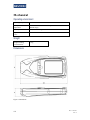
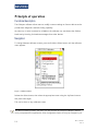
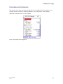
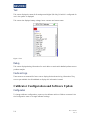
1
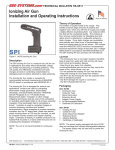
CANopen
Calibrator
Reference
Manual
Document no:
177/52503
Rev. A
Sevcon Ltd
Kingsway South
Gateshead, NE11 0QA
England
Tel +44 (0)191 497 9000
Fax +44 (0)191 482 4223
[email protected]
Sevcon, Inc.
155 Northboro Road
Southborough, MA 01772
USA
Tel (508) 281 5500
Fax (508) 281 5341
[email protected]
Sevcon SA
12 Rue Jean Poulmarch
95100 Argenteuil
France
Tel +33 (0)1 34 10 95 45
Fax +33 (0)1 34 10 61 38
[email protected]
Sevcon Japan
4-12-1 Shinbashi
Minato-Ku, Tokyo 105-0004
Japan
Tel +81 (0) 3 (5408) 5670
Fax +81 (0) 3 (5408) 5677
[email protected]
Sevcon Asia Ltd
4th Floor, Eun-Hyae Building
463-1, Sang-dong
Wonmee-gu, Bucheon City
Kyunggi-do 420-030
Korea
Tel +82 (0)32 215 5070
Fax +82 (0)32 215 8027
[email protected]
www.sevcon.com
Table of Contents
Chapter 1:
Introduction
1-1 About CANopen Calibrator documentation .......................................... 1-2 This version of the manual .............................................................................................................. 1-2 Copyright ........................................................................................................................................ 1-2 Scope of this manual ....................................................................................................................... 1-2 Related documents .......................................................................................................................... 1-2 Drawings and units ......................................................................................................................... 1-2 Warnings, cautions and notes.......................................................................................................... 1-3 Product identification label .................................................................... 1-4 Technical support ................................................................................... 1-4 Product warranty .................................................................................... 1-4 Chapter 2:
About the Calibrator
2-1 Introduction ............................................................................................ 2-2 Standard features and capabilities ......................................................... 2-2 Mechanical package ........................................................................................................................ 2-2 Intended use of the CANopen calibrator ........................................... Error! Bookmark not defined. Available accessories ...................................................................................................................... 2-3 Safety and protective functions ............................................................. 2-4 General ............................................................................................................................................ 2-4 Chapter 3:
Connection
3-1 Connecting the Calibrator ...................................................................... 3-2 Connector ........................................................................................................................................ 3-2 CAN bus termination ...................................................................................................................... 3-2 Signal connections ................................................................................. 3-2 Chapter 4:
Specification
4-1 Electrical ................................................................................................ 4-2 Input voltage ................................................................................................................................... 4-2 Output protection ............................................................................................................................ 4-2 CAN interface ................................................................................................................................. 4-2 Control inputs ................................................................................................................................. 4-2 Isolation .......................................................................................................................................... 4-2 EMC ................................................................................................................................................ 4-2 Regulatory compliance ................................................................................................................... 4-3 Mechanical ............................................................................................. 4-4 Operating environment ................................................................................................................... 4-4 Weight............................................................................................................................................. 4-4 Dimensions ..................................................................................................................................... 4-4 Chapter 5: Calibrator Usage
5-1 Principle of operation............................................................................. 5-2 Functional description ..................................................................................................................... 5-2 Navigation ....................................................................................................................................... 5-2 Splash Screen .................................................................................................................................. 5-3 System Overview ............................................................................................................................ 5-4 Personalities and Configuration ...................................................................................................... 5-5 Test ................................................................................................................................................. 5-6 Debug .............................................................................................................................................. 5-6 Faults and Logs ............................................................................................................................... 5-6 Calibrator Configuration and Software Update ..................................... 5-6 Configuration .................................................................................................................................. 5-6 Software Update.............................................................................................................................. 5-7 ii
Doc. 177/52503
Rev A
Chapter 1:
Introduction
About CANopen Calibrator documentation
This version of the manual
This version of the CANopen calibrator manual replaces all previous versions. Sevcon has
made every effort to ensure this document is complete and accurate at the time of printing.
In accordance with our policy of continuing product improvement, all data in this document
is subject to change or correction without prior notice.
Copyright
This manual is copyrighted 2009 by Tech/Ops Sevcon. All rights are reserved. This manual
may not be copied in whole or in part, nor transferred to any other media or language,
without the express written permission of Tech/Ops Sevcon.
Scope of this manual
This manual provides information on how to use the CANopen calibrator and on which
Sevcon products the CANopen calibrator is compatible with. Documents proving further
details of contents of the CANopen calibrator trees and system fault help are referenced
here.
Related documents
The following documents are available from Sevcon:
•
The Object Dictionary providing important information about CANopen communication
with the CANopen calibrator.
Drawings and units
Orthographic illustrations in this manual are drawn in Third Angle Projection. SI units are
used throughout this manual.
1-2
Doc. 177/52503
Rev A
Introduction
Warnings, cautions and notes
Special attention must be paid to the information presented in Warnings, Cautions and
Notes when they appear in this manual. Examples of the style and purpose of each are
shown below:
A WARNING is an instruction that draws attention to the risk of injury or death and tells
you how to avoid the problem.
A CAUTION is an instruction that draws attention to the risk of damage to the product,
process or surroundings.
A NOTE indicates important information that helps you make better use of your Sevcon
product.
Doc. 177/52503
Rev. A
1-3
Product identification label
If you have a customized product your unique identifier will appear at the end of the Type
number. When discussing technical issues with Sevcon always have your product’s Type
number, Part number and Serial number available
Error! Reference source not found. shows a typical product identification label.
Technical support
For technical queries and application engineering support on this or any other Sevcon
product please contact your nearest Sevcon sales office listed on the inside front cover of
this manual. Alternatively you can submit enquiries and find the details of the nearest
support center through the Sevcon website, www.sevcon.com.
Product warranty
Please refer to the terms and conditions of sale or contract under which the CANopen
calibrator was purchased for full details of the applicable warranty.
1-4
Doc. 177/52503
Rev A
Chapter 2:
About the Calibrator
Introduction
The CANopen calibrator can be used to assist in setting up and maintaining Sevcon
CANopen compliant devices. It has the following features:
•
240x320, 256 colour display.
•
Auto-baud rate detection.
•
System status overview.
•
Single and multi-node support.
•
Reads/writes a wide range of commonly used vehicle system settings.
•
Displays I/O + motor/vehicle status information
•
Displays any active faults and provides basic diagnostic information.
•
Fully flash programmable for calibrator software updates.
Standard features and capabilities
Mechanical package
2-2
Doc. 177/52503
Rev A
About the Calibrator
UP
Button
SELEC
T
Button
DOWN
Button
Figure 1 Mechanical package
Available accessories
The following accessories are available from Sevcon:
•
External harness to connect to system
•
Drive Wizard - PC based configuration tool
Doc. 177/52503
Rev. A
2-3
Safety and protective functions
General
Do not adjust the value of any parameter unless you fully understand the effect of this
change. You should have read and understood the User Manual for all the connected
devices before connecting the calibrator to them..
Do not attempt to open the calibrator as there are no serviceable components. Opening the
calibrator will invalidate the warranty.
Electric vehicles are subject to national and international standards of construction and
operation which must be observed.
2-4
Doc. 177/52503
Rev A
Chapter 3:
Connection
Connecting the Calibrator
Connector
The calibrator is supplied with a detachable external harness.
CAN bus termination
The calibrators primary function is to connect to an existing multi node fully terminated CAN
bus.
The calibrator contains no internal bus termination. The CANbus it connects to should
already be properly terminated. If you use the calibrator with a single stand alone device
then you should check that the connection is properly terminated by connecting a
termination adapter to the external harness as required.
If the calibrator fails to detect a standalone device then you should check that the CAN bus
has correct termination
Signal connections
Pin
Name
Type
What to connect
Maximum
rating
1
Not
connected
n/a
Not connected
2
Gnd
Power
+24Volt supply return
3
Not
connected
n/a
Not connected
4
VPos
Power
+24Volt supply
35V
5
CAN Hi
Comms
CAN Hi
35V
6
CAN Lo
Comms
CAN Lo
35V
-35V
Table 1 Connector A pin out and wiring information
Pins are protected against short-circuits to the battery positive or negative voltages.
3-2
Doc. 177/52503
Rev A
Chapter 4:
Specification
Electrical
Input voltage
Working voltage
limits:
15V to 28.8V
Input protection:
Input protected against reverse connection of supply
Maximum current draw 100mA
Output protection
Short-circuit:
Protected against short circuit to supply
CAN interface
CAN protocol:
CANopen profiles DS301, DS401 and DS402 are supported.
Physical layer uses ISO11898-2.
Baud rates supported:
1Mbits/s, 500 kbits/s, 250 kbits/s, 125 kbits/s, 100 kbits/s, 50
kbits/s
Control inputs
User interface
3 button keypad input
Isolation
Any terminal to the
case:
TBD
(Gen4:Withstands 2 kV d.c.
Meets EN1175-1:1998 and ISO3691
Complies with IEC-60664
EMC
Radiated emissions:
EN12895 (Industrial Trucks – Electromagnetic Compatibility)
EN 55022:1998, 6, class B
EN 12895:2000, 4.1 Emissions. When part of a system with a
motor operating,
FCC Part 15, Radiated Emissions. Meets the standards given in
FCC Part 15, Section 15.109:
Conducted emissions:
No mains port, therefore not required
Radiated RF field:
EN 61000-4-3, 5.1 Test Level: user-defined test level of 12 V/m
EN 12895:2000, 4.2 Immunity
EN 61000-4-6, Table 1 - Test Levels
Electrical fast transient:
EN 61000-4-4, Table 1 - Test Levels, Level 2
4-2
Doc. 177/52503
Rev A
Specification
Electrostatic
discharge:
Electrical surge:
EN 12895:2000, 4.2 Electrostatic Discharge
4 kV contact discharge
8 kV air discharge
EN 61000-4-5:1995, Table A.1 – Selection of Test Levels, Class
3
Regulatory compliance
Designed to meet:
Doc. 177/52503
Rev. A
EN1175-1:1998 (which covers EN1726 for the controller)
ISO 3691
UL583
ASME/ANSI B56.1:1993
4-3
Mechanical
Operating environment
Operating temperature:
-10°C to +50°C
Non-operation
temperature:
-40°C to +85°C (can be stored for up to 12 months in this
ambient range)
Humidity:
95%(non-condensing) at 40°C and 3% at 40°C
Ingress of dust and
water:
IP42
Weight
Weight including
external harness:
0.3 kg
Dimensions
.
Figure 2 Dimensions
4-4
Doc. 177/52503
Rev A
Chapter 5:
Calibrator Usage
Principle of operation
Functional description
The CANopen calibrator allows users to modify common settings on Sevcon devices and to
provide basic diagnostic and fault finding capability.
At power up or when connected to a CANbus, the calibrator can auto-detect the CANbus
baud-rate by listening for heartbeat messages from other devices.
Navigation
To change between calibrator screens, press and hold the Select button until the calibrator
menu appears.
Figure 3 Calibrator Menu
Release the Select button, then select the appropriate screen using the Up/Down buttons
and press Select again.
This can be done on any calibrator screen.
As well as accessing screens, the menu can also be used to change a CANopen network
from pre-operational to operational. Some configuration items can only be changed in pre-
5-2
Doc. 177/52503
Rev A
Calibrator Usage
operational. The system will not drive or close it’s line contactor if pre-operational, so always
ensure the system is set back to operational after all changes are made.
Most of the screens utilize tree structures to display information. To navigate the trees, use
the Up/Down buttons to select tree nodes and branches and the Select button to
expand/collapse branches. To change values, use the Select button to select the value, then
Up/Down to change the value, then Select again to transmit the value to the controller.
Splash Screen
At power up the calibrator displays a splash whilst it analyses the CANbus network, identifies
nodes and logs in to the system. Progress is shown at the bottom of the splash screen.
Figure 4 Splash Screen
The splash screen image can be made customer dependant. The example above is the
generic Sevcon splash screen.
Doc. 177/52503
Rev. A
5-3
System Overview
The system overview screen is shown below.
Figure 5 System Overview
System status is represented by one of the following icons at the top of screen:
The system is operational, with no active faults
The system is operational, with active faults
The system is pre-operational mode. This mode is used to set up parameters that
cannot safely be change during normal operation.
Each device in the network is displayed. Select a device to display more information and fault
status. Press Select to cycle through each active fault on the selected device.
5-4
Doc. 177/52503
Rev A
Calibrator Usage
Personalities and Configuration
Both these screens allow the system configuration to be modified. The Personalities screen
displays the most commonly modified parameters. The Configuration screen displays
additional parameters which can be modified.
Figure 6 Personalities and Configuration
Doc. 177/52503
Rev. A
5-5
Test
This screen displays the state of all analogue and digital I/O. Only I/O which is configured for
use in the system is displayed.
This screen also displays battery voltage, hours counters and motor status.
Figure 7 Test
Debug
This screen displays debug information for each device to assist with detailed performance or
problem analysis.
Faults and Logs
These screens are reserved for future use to display fault and service log information. They
are not yet available. Use DriveWizard to display this information instead.
Calibrator Configuration and Software Update
Configuration
To change calibrator configuration, power up the calibrator with no CANbus connected. Use
the Configuration menu to change calibrator settings.
5-6
Doc. 177/52503
Rev A
Calibrator Usage
The CANbus and Calibrator branches in the Configuration tree are reserved for the
calibrator. These branches are still available even when other devices are connected to the
CANbus.
Software Update
It is possible to update the firmware of the calibrator controller, using Sevcon’s DriveWizard
configuration tool.
Please contact Sevcon for assistance with this process.
Doc. 177/52503
Rev. A
5-7