1
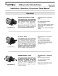
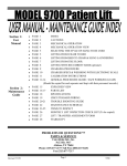
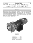
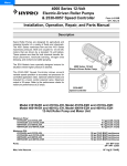
Menu
Models 9700B/9700S AQUA-TIGER
Centrifugal DC Pumps
Form L- 0335C
(1/08)
Installation, Operation, Repair and Parts Manual
Description
Specifications
Body/Impeller:9700B - Bronze/ 9700S - Stainless Steel
Seal:....... ..9700B: Lip-type Viton* / 9700S: Mechanical
Port Size:.................................................. 3/4" NPT (F)
Max. Temperature:..............................................140o F
Max. PSI:.............................................................7.0 psi
Max. Current:................................................. 5.0 Amps
Weight:........................................5 lbs. (2.3 kg) approx.
Motor:........................ Stainless steel shaft, permanent
magnet, fully enclosed, ignition protected
Performance Chart
Model 9700 Aqua-Tiger
VOLTS
Application
The Aqua-Tiger is suitable for general pumping applications
where a flooded intake is provided. Typical applications include livewell filling and circulation and any other application
not requiring a self-priming pump.
13.5
(Alternator) Engine Running PSI AMPS GPM
1
2
3
4
5
6
7
5.5
5.3
5.0
4.9
4.5
4.1
3.7
19.0
16.5
14.0
12.5
10.0
6.5
2.7
General Safety Information
1. WARNING: DO NOT pump solvents, thinners or
gasoline, as explosion may result causing personal
injury or death and/or property damage. DO NOT
use in explosive atmospheres. The pump should
be used only with liquids compatible with the pump
component materials. Failure to follow this warning
will void the product warranty.
2. WARNING: DO NOT operate with any of the mounting bolts removed from the motor case. Explosion
resulting in personal injury, death or property damage may occur. Case openings must be sealed to
avoid explosion and maintain ignition protected
rating.
3. Do not pump liquids at temperatures higher than the
recommended maximum temperatures (140o F).
4. Disconnect power before servicing.
5. Drain all liquids from the system before servicing any
component.
6. Check hose for weak or worn condition before each
use. Make certain that all connections are tight and
secure.
7. Periodically inspect the pump and the system components. Perform routine maintenance as required (see
Maintenance section).
8. Do not use these pumps for pumping water or other
liquids for human or animal consumption.
Hazardous Substance Safety Information
1. Always drain and flush the pump before servicing or
disassembling for any reason (see instructions).
2. Always drain and flush pumps prior to returning unit for
repair.
3. Never store pumps containing hazardous chemicals.
4. Before returning the pump for service/repair, drain out all
liquids and flush the unit with neutralizing liquid. Then,
drain the pump. Attach a tag or include a written notice
certifying that this has been done. Please note that it
is illegal to ship or transport any hazardous chemicals
without United States Environmental Protection Agency
Licensing.
Installation and Operation
The pump must be mounted in a dry location. The motor is
not waterproof; therefore, it must not be submerged. The
unit can be operated in any positon. It is advantageous to
mount the pumps so the water dripping from a loose port
connection will not wet the motor. The pump head may be
mounted at 90o increments on the motor to allow mounting
as needed.
ELECTRICAL HOOKUP
WARNING: If the pump is operated in an area containing
flammable vapors, wire leads must be joined by insulated
mechanical locking connectors. Loose or inadequate wire
connections can spark resulting in explosion. Property
damage, injury or death may occur.
CAUTION: Lead wires on the motor must not be shortened or the warranty will be voided.
OPERATION
Try not to run the pump dry because doing so shortens the
seal life. If you must run the pump dry, do so only for short
periods of time. The pump may run against a closed outlet.
Small particles will pass through the pump, so a 50-mesh
intake strainer should be fitted to the pump.
CAUTION: The motor runs hot, up to 180o F on the motor
case. Contact during operation may cause a burn.
Positive terminal of the battery is connected to an overload
protected distribution panel. The red lead with the fuse holder
is connected to the distribution panel. The black wire is connected to the negative terminal of the battery. For proper
operation, the motor must rotate clockwise when viewed from
the pump end. The proper sized fuse has been installed in the
fuse holder. If this fuse blows, replace it with the same size
fuse after determining the reason for the blown fuse. Use the
proper wire size as determined by the wiring table.
Overload Protected�
Distribution Panel
Red Wire
Black Wire
Fuse
Outlet
Outlet
Wiring Table for 9700B
Connection length
between battery
Inlet
Wire Gage
and motor
1-10 ft......................................#12
11-20 ft.....................................#10
12-30 ft.....................................#8
Fuse Sizes for 9700B
Approximate Amp Draw......... 8
Fuse Size............................. 10
Models 9700B and 9700S
7
8
9
6
11
4
2
5
3
1
10
12
Ref. Qty.
No. Req'd.
Description
1
2
3
4
5
6
7
8
9
10
11
12
3
1
1
1
1
1
2
1
1
4
1
1
Cover Screw
Cover O-ring, Viton*
Impeller Mechnical Seal Assy.**
Pipe Plug Hex Head Screw
Housing Lip Seal, Viton*
Grommet
Motor 12VDC (TENV)
Set Screw
Model 9700B
Part Number
Model 9700S
Part Number
2210-0124
19893
19898
19892
N/A
00336 2210-0123
19891
19928
21138 23697S
19929
2210-0124
23660
19898
23659
23665S
21059
2210-0123
23627
N/A
21138
23697S
19929
TENV = Totally-Enclosed Non-Ventilated
(**) Mechanical seals have carbon ceramic wearing faces and 316 Stainless Steel spring components with Viton elastomers.
Manufacturer reserves the right to change parts without notification.
IMPORTANT:
When ordering parts, give PART NUMBER
and PART DESCRIPTION. Reference
Numbers are used ONLY to point out parts
in the drawing and are NOT to be used as
ordering numbers.
*Viton is a trademark of E.I. Dupont deNemour
and Company
Maintenance
MAINTENANCE
Check all electrical and plumbing connections periodically.
In salt water applications, corrosion of the electrical connections can cause a loss of performance or non-operation. The
motor should be protected with a corrosion inhibiting spray.
Any rust should be removed and the motor repainted.
DISASSEMBLY
1. Remove the cover screws, cover and o-ring.
2. Remove the pipe plug on the side of the housing and
rotate the impeller so the set screw aligns with the plug
hole. Insert a 3/32" allen wrench through the plug hole
and loosen the impeller set screw. Remove the impeller.
3. Remove the screws that secure the housing to the motor, and remove the housing.
4. From the inside of the housing, insert a dowel into the
seal area and press the seal out of the seal bore.
ASSEMBLY
1. From the rear of the housing, press the seal into the
seal bore with the open lip toward the pump cavity.
2. Apply a small amount of grease to the motor shaft in the
area where the seal contacts it. Slide the housing onto
the shaft and secure it to the motor with the (2) two hex
head screws.
3. Align the impeller set screw with the flat on the motor
shaft and slide the impeller onto the shaft until it contacts the rear of the housing. Slide the impeller forward
1/32"-1/16" and secure it with the set screw. Rotate the
impeller by hand to ensure that it does not rub on the
housing. Reinstall the pump plug in the housing.
4. Clean the surfaces of the cover and housing where they
make contact. A small amount of grease on the o-ring
will ease installation. Place the o-ring on the cover.
Align the cover with the housing and secure it with the
(3) three cover screws.
Dimensions are in inches.
Care of the Pump
AFTER USE PUMP CARE
A. GUMMING — Gumming or corrosion inside the pump
can be prevented by thoroughly flushing the pump clean
with water or a liquid that will neutralize the liquid pumped.
(For many liquids, a solution of 1 gallon ammonia mixed
with 6 gallons of water works well.)
B. To PREVENT RUST/CORROSION, we recommend
(after Step A) flushing the pump with permanent-type
automobile radiator antifreeze containing a rust inhibitor,
and then preventing air from getting in the pump. Use a
50-50 solution of antifreeze and water. Flush it through the
pump, and then drain it. Plug the ports to keep air from
getting into the pump during storage. Cleaning and rust
protection should be done when the pump will be stored
away for more than two to three days.
Limited Warranty on Hypro Pumps and Other Hypro Products
Hypro warrants to the original purchaser of its products (the “Purchaser”) that such products will be free from defects in material and workmanship under normal use for the period of one (1) year for all products except: oil crankcase plunger pumps will be free from defects in material
and workmanship under normal use for the period of five (5) years, and accessories will be free from defects in material and workmanship under
normal use for the period of ninety (90) days. In addition, Hypro warrants to the purchaser all forged brass pump manifolds will be free from
defects in material and workmanship under normal use and from damage resulting from environmental conditions for the life of the pump.
“Normal use” does not include use in excess of recommended maximum speeds, pressures, vacuums and temperatures, or use requiring handling of fluids not compatible with component materials, as noted in Hypro product catalogs, technical literature, and instructions. This warranty
does not cover freight damage, freezing damage, normal wear and tear, or damage caused by misapplication, fault, negligence, alterations, or
repair that affects the performance or reliability of the product.
THIS WARRANTY IS EXCLUSIVE. HYPRO MAKES NO OTHER WARRANTY, EXPRESS OR IMPLIED, INCLUDING BUT NOT LIMITED TO
ANY WARRANTY OF MERCHANTABILITY OR FITNESS FOR A PARTICULAR PURPOSE.
Hypro’s obligation under this warranty is, at Hypro’s option, to either repair or replace the product upon return of the entire product to the Hypro
factory in accordance with the return procedures set forth below. THIS IS THE EXCLUSIVE REMEDY FOR ANY BREACH OF WARRANTY.
IN NO EVENT SHALL HYPRO BE LIABLE FOR ANY INCIDENTAL OR CONSEQUENTIAL DAMAGES OF ANY KIND, WHETHER FOR
BREACH OF ANY WARRANTY, FOR NEGLIGENCE, ON THE BASIS OF STRICT LIABILITY, OR OTHERWISE.
Return Procedures
All pumps or products must be flushed of any chemical (ref. OSHA Section 0910.1200 (d)(e)(f)(g)(h)) and hazardous chemicals must
be labeled before being shipped* to Hypro for service or warranty consideration. Hypro reserves the right to request a Material Safety
Data sheet from the Purchaser for any pump or product Hypro deems necessary. Hypro reserves the right to “disposition as scrap” pumps or
products returned which contain unknown substances, or to charge for any and all costs incurred for chemical testing and proper disposal of
components containing unknown substances. Hypro requests this in order to protect the environment and personnel from the hazards of handling unknown substances.
For technical or application assistance, call the Hypro Technical/Application number: 1-800-445-8360.
The Hypro Service and Warranty number is: 1-800-468-3428, or Hypro Service and Warranty FAX: (651) 766-6618.
*Carriers, including U.S.P.S., airlines, UPS, ground freight, etc., require specific identification of any hazardous materials being shipped.
Failure to do so may result in a substantial fine and/or prison term. Check with your shipping company for specific instructions.
Printed in the USA
2008 Hypro