1
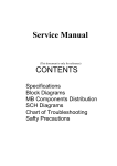
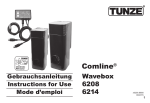
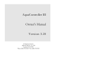
AquaController Apex Variable Speed/Dimming Module Setup Guide Table of Contents VARIABLE SPEED/DIMMING MODULE – INTRODUCTION ............................................... 1 FEATURES ...................................................................................................................... 1 PHYSICAL INSTALLATION .............................................................................................. 1 Initial Connections.............................................................................................................. 2 Startup ............................................................................................................................. 2 VERIFY THE INSTALLATION ........................................................................................... 2 UPDATE VDM FIRMWARE................................................................................................ 2 CONFIGURING THE VDM ................................................................................................. 2 Pump Profile Type ............................................................................................................ 3 Ramp Profile Type ............................................................................................................ 4 Weather Profile Type ........................................................................................................ 4 PROGRAMMING EXAMPLES ............................................................................................. 4 Simple Light Program Example ............................................................................................ 4 Advanced Light Program Example ........................................................................................ 5 Advanced Pump Example .................................................................................................... 6 NEPTUNE SYSTEMS LIMITED WARRANTY ....................................................................... 9 VARIABLE SPEED/DIMMING MODULE – INTRODUCTION Congratulations on your purchase of the AquaController Apex expansion accessory. The AquaController Apex Variable Speed/Dimming Module (VDM) provides the ability to control the Aqua Illumination LED lighting systems as well as adding 4 additional variable speed ports. The Aqua Illumination‟s interface allows for the independent control of both the blue and white LEDs. In addition, sunrise/sunset, cloud and lightning simulation are also available. The 4 variable speed ports (0-10V interface) allow precise 0 to 100% control of Tunze stream pumps as well as dimming of some compatible ballasts. You can control them based on time of day, in response to feed timers, or any event you can think of using the powerful Apex programming language. The AquaController Apex System delivers an expandable, professional quality aquarium controller at hobbyist prices. The AquaController Apex is the most flexible, expandable system on the market today. FEATURES Supports the Aqua Illumination LED lighting systems through a serial communication link. Sunrise/Sunset Simulation, Cloud Simulation, and Lightning*. Lighting and pump modes can be changed based on conditions and events throughout the day using powerful Apex programming commands. 4 independently variable speed ports (0-10V) Variable speed ports can be used for light dimming, Tunze stream variable speed control, or with other 0-10V compatible devices. The VDM attaches to and is powered by the Apex system via AquaBus. Automatic Plug N Play for easy setup and configuration. Upgradable firmware through AquaBus. Multi-color LED Status indicator. 2 AquaBus ports for flexible system connections. Comes with a 3' AquaBus cable. Compatible with Apex and Apex Lite systems *Lightning simulation only available on Aqua Illumination serial interface. PHYSICAL INSTALLATION WARNING: Your Apex Base Module must be running firmware version 4.04 or higher to support the Wireless Expansion Module (VDM). The current firmware version can be checked from the Apex Display on the Self Test screen. If needed, please upgrade the Apex Base Module firmware to 4.04 or higher before proceeding with the installation. See the Apex Setup and Programming Guide for firmware upgrade instructions. The AquaController VDM should be securely mounted in a location free from moisture. Use wood screws through the mounting tabs of the expansion module case or if mounting on drywall, use drywall anchors (mounting hardware not included). Mount all modules above the water line of the aquarium. Be sure to utilize drip loops on all power cords, AquaBus cables and probe cables. WARNING: Water damage will void your warranty! Mount all modules in locations safe from moisture exposure. AquaController Apex Wireless Expansion Module - Setup Guide Page 1 INITIAL CONNECTIONS Plug one end of the included AquaBus cable into one of the AquaBus ports on the VDM and the other end into an available AquaBus port on your existing Apex system. It makes no difference which AquaBus port is used and you do not need to power down the system when connecting AquaBus accessories as the system is plugand-play. WARNING: NEVER plug standard USB devices into any AquaBus connector or AquaBus accessories into computer USB ports. Damage to the AquaBus accessory and/or USB device may result. When connecting the VDM to an AquaIlluminations lighting system using the optional interface cable, it is important to plug the phono connector first into the AI Lights and then plug the DB9 end into the serial connector on the VDM. Failure to do it in this order may result in damage to the VDM. STARTUP As soon as the VDM is connected to an active AquaBus, the module will power up and begin to initialize. When first connected to an AquaController Base Module (through the AquaBus), the VDM will automatically be assigned an AquaBus address and be added to the AquaController configuration. The LED Status indicator on the VDM will flash yellow while it is being initialized. Once initialized, the LED Status indicator will be solid green. The LED Status indicator will flash when the VDM is powered on and communication with the AquaController Base Module is lost. VERIFY THE INSTALLATION Verify the VDM was initialized and added to the AquaController Apex configuration: Apex Display: Setup – Module Setup – Modify Name – from this screen, you can see all AquaBus modules installed on the system. Web Interface: Configuration – Module Setup – Verify the VDM is listed in the Apex Module List. Also 6 outlets are automatically created which can be configured Configuration – Outlet Setup. The initial names of the VDM outlets are VarSpd1_X_1 to VarSpd4_X_4, BluLED_X_5, and WhtLED_X_6. UPDATE VDM FIRMWARE A new version of firmware for the VDM may be included with Apex Base Module firmware updates. You should check the firmware version status when the VDM is first installed and after updating the AquaController Base Module firmware. See the section titled Updating Firmware in the AquaController Apex Setup and Programming Guide for instructions to update AquaController Apex Base Module and WXM firmware. To check or update an Apex module firmware: Apex Display: Setup – Module Setup – Update Module – use the up/down arrows to highlight the Apex module to update, push Select to update. Web Interface: Configuration – Module Setup – in the Module Configure area, in the Module: box, select the Apex module to update from the dropdown list, click the Update Firmware radio button, click the Submit Module Update button, a new browser window will open to display the update status. CONFIGURING THE VDM When the VDM is installed the Apex automatically installs 4 variable speed outlets (named VarSpd1_X_1 to VarSpd1_X_4) that can be used to control Tunze Streams Pumps or lighting ballasts with 0-10V variable AquaController Apex Wireless Expansion Module - Setup Guide Page 2 intensity features. Also it automatically adds two lights (to the system to support the Aqua Illuminations interface). The default names for the LED lights are BluLED_X_5 and WhtLED_X_6 for the blue and white LEDs respectively. The 4 variable speed ports and the 2 Aqua Illumination lights can be turned on and off with normal programming commands, however this does not provide a way to vary the output voltage which in turn varies the speed of the pump or brightness of the lighting. To take full advantage of variable/dimming features, we use Profiles. You can define up to 16 Profiles, each of which can define a unique set of operating conditions. The Profile in use for a port can be switched based on programming events such as feed timers, time of day, switch levels, etc. Each variable speed port can be programmed to use a different Profile, or they all can use the same Profile, it is up to you. The VDM supports 3 different types of Profiles; pump, ramp, weather. PUMP PROFILE TYPE The Pump Profile is typically used to oscillate the speed of a pump from one speed to a higher speed and back. Popular use of this feature is to create resonant or chaotic waves in larger tanks depending on if the waves are synchronized or not. The Pump Profile uses the Minimum Intensity setting to specify the speed of the pump when set “off” by the Profile and the Maximum Intensity setting to specify the speed of the pump when set “on” by the Profile. When the pump is turned off by a line of program code like “If FeedA then OFF”, the pump will be totally off (the Minimum Intensity setting is not used). The pump Profile contains the following parameters: Synchronize: when enabled, a port using this Profile will synchronize its Initial Off time with the previous pump Profile (i.e. if enabled on Profile 2, it will sync with Profile 1). Synchronize is useful for creating large waves through constructive interference with pumps on either side of the tank. Divide by 10: when enabled, all times in the Profile are divided by 10 (i.e. 56 seconds becomes 5.6 seconds). Figure 1 - Profiles Setup Screen Initial Off Time: when a pump with this Profile is first activated, it will be OFF initially for this time (in seconds unless divide by 10 is enabled). On Time: once the Initial Off Time expires, the pump will be ON for this amount of time (in seconds unless divide by 10 is enabled). Off Time: once the On Time expires, the pump will be OFF for this amount of time (in seconds unless divide by 10 is enabled). Minimum Intensity: the port output in percent when the pump is “off” Maximum intensity: the port output in percent when the pump is “on” WARNING: Tunze recommends an intensity of 30% or higher for Tunze Streams Pumps. For best results and longevity of your pumps, never set the Minimum Intensity lower than 30%. For example, assume the following settings: AquaController Apex Wireless Expansion Module - Setup Guide Page 3 Synchronize = off Divide by 10 = off Initial off time = 10 On time = 15 Off time = 20 Minimum Intensity = 30 Maximum Intensity = 70 Using this Profile, the pump will run at 30% for 10 seconds, 70% for 15 seconds, 30% for 20 seconds, 30% for 10 seconds, 70% for 15 seconds, 30% for 20 seconds, etc. RAMP PROFILE TYPE The Ramp Profile is used to ramp the port output voltage (up or down) from one intensity to another over a period of time. It is typically used to ramp lights on or off but can also be used with pumps to simulate varying intensity of tidal currents for example. Ramp Time: period in minutes over which the ramp should occur. Start Intensity: the starting intensity in percent End Intensity: the ending intensity in percent WEATHER PROFILE TYPE The Weather Profile is used to simulate weather changes. Sunny, cloudy, and lightning effects can all be specified with this profile. Light Maximum Intensity (%): the lighting intensity during sunny periods. Cloudy light Intensity (%): the intensity of the lights during a cloudy period. Cloud Duration (MMM): the number of minutes for each cloudy period. Cloudy Time (%): the percent of time that it will be cloudy. Probability of Lightning (%) : a metric which sets the frequency of a lightning strike during cloud cover. 0% means no lightning will occur and a 100% value means that lightning will occur almost continuously. This parameter is only valid for the Aqua Illumination White lights. Not valid for the variable speed ports or the blue LEDs. Lightning Intensity (%): the lightning white light intensity during a lightning strike. It can be set between 0 and 100%. This parameter is only valid for the Aqua Illumination White lights. Not valid for the variable speed ports or the blue LEDs. PROGRAMMING EXAMPLES Refer to the Apex Owners for instructions on how to configure and program outlets. These examples will give you a sample of the flexible control that is available by the VDM to control pump and lighting systems. SIMPLE LIGHT PROGRAM EXAMPLE The following program and profiles are used for each of the Aqua Illumination outlets. They cause both the blue and white LEDs lights to simulate sunrise (0% to 100% intensity) from 8:00 to 9:00, turn full on from 9:00 to 20:00, and then simulate sunset (100% to 0% intensity) from 20:00 to 21:00. AquaController Apex Wireless Expansion Module - Setup Guide Page 4 <BluLED_X_5> Fallback Off Set OFF If Time 8:00 to 9:00 Then RampUp If Time 9:00 to 20:00 Then ON If Time 20:00 to 21:00 Then RampDn <WhtLED_X_6> Fallback Off Set OFF If Time 8:00 to 9:00 Then RampUp If Time 9:00 to 20:00 Then ON If Time 8:00 to 9:00 Then RampDn The RampUp and RampDn Profiles are defined as follows: <RampUp Profile> Ramp time: 60 minutes Start intensity: 0 End intensity: 100 <RampDn Profile> Ramp time: 60 minutes Start intensity: 100 End intensity: 0 ADVANCED LIGHT PROGRAM EXAMPLE The following example assumes that the VDM is connected to the Aqua Illumination lighting system via our interface cable (part # AICABLE). The desired operation of the lights is to simulate sunrise and sunset, have cloud cover and lightning on certain days, and a lunar simulation. <BluLED_X_5> Fallback Off If Moon 000/000 Then MoonInt If Time 8:00 to 9:00 Then RampUp If Time 9:00 to 20:00 Then ON If Time 20:00 to 21:00 Then RampDn If Outlet Storm = ON Then Weather <WhtLED_X_6> Fallback Off Set OFF If Time 8:00 to 9:00 Then RampUp If Time 9:00 to 20:00 Then ON If Time 20:00 to 21:00 Then RampDn If Outlet Storm = ON Then Weather A virtual outlet „Weather‟ is also declared which will schedule when storms should occur: AquaController Apex Wireless Expansion Module - Setup Guide Page 5 <Storm> Set Off If Time 18:00 to 18:30 Then ON If DoW S-T-T-S Then OFF And the profiles are defined as: <RampUp Profile> Ramp time: 60 minutes Start intensity: 0 End intensity: 100 <RampDn Profile> Ramp time: 60 minutes Start intensity: 100 End intensity: 0 <Weather Profile> Light maximum intensity: 100 Cloudy light intensity: 50 Cloud duration (MMM): 5 Cloudy time (%): 50 Probability of lightning (%): 50 Lightning intensity (%): 100 ADVANCED PUMP EXAMPLE The following program assumes that there are two pumps in the Aquarium – one on the right side, and one on the left side. This example shows how each pump can be controlled independently, and its mode of operation changed multiple times throughout the day. The following programs are used for each of the VorTech outlets. <PumpLeft> Set Calm If Time 8:00 to 10:00 Then WaveLeft If Time 12:00 to 14:00 Then ON If Time 16:00 to 20:00 Then OFF If Time 22:00 to 06:00 Then Night If FeedA 000 Then Off <PumpRight> Set Calm If Time 8:00 to 10:00 Then WaveRight If Time 12:00 to 14:00 Then OFF If Time 16:00 to 20:00 Then ON If Time 22:00 to 06:00 Then Night AquaController Apex Wireless Expansion Module - Setup Guide Page 6 If FeedA 000 Then Off AquaController Apex Wireless Expansion Module - Setup Guide Page 7 The following table shows the profiles required for this program example. Profile Name WaveLeft WaveRight Calm Night Mode Notes Max Intensity 100%, Min Intensity 0%, Int Off 10, On 10, Off 0 Pump Max Intensity 100%, Min Intensity 0%, Int Off 0, On 10, Off 10 Ramp Start Int 50%, End Int 50%, Time 1 Ramp Start Int 30%, End Int 30%, Time 1 Table 1 - Profiles Defined for Program Example Pump Table 2 - Pump States lists the various states of the pump at times throughout the day. If FeedA cycle is initiated both pumps will be shut off. Time 08:00 to 10:00 10:00 to 12:00 12:00 to 14:00 14:00 to 16:00 16:00 to 20:00 20:00 to 22:00 22:00 to 6:00 6:00 to 8:00 Left Pump Status Right Pump Status Pumps cycle from 0 to 100% Pump cycles from 0 to 100% every 10 seconds. every 10 seconds Runs 180 degrees out of phase with the left pump 50% Intensity 50% Intensity 100% Intensity Off 50% Intensity 50% Intensity Off 100% Intensity 50% Intensity 50% Intensity 30% Intensity 30% Intensity 50% Intensity 50% Intensity Table 2 - Pump States AquaController Apex Wireless Expansion Module - Setup Guide Page 8 NEPTUNE SYSTEMS LIMITED WARRANTY Neptune Systems warrants this product to be free from defects in material and workmanship for a period of 1 year from the date of purchase. Probes carry a 90-day warranty. If repair or adjustment is necessary and has not been the result of abuse, misuse, or accidental damage, within the 1-year period, please return the product with proof of purchase, and correction of the defect will be made without charge. For your protection, items being returned must be carefully packed to prevent damage in shipment and insured against possible damage or loss. Neptune Systems will not be responsible for damage resulting from careless or insufficient packaging. Before returning please obtain a return authorization (RMA) number from Neptune Systems at (408) 578-3022. Returned merchandise will not be accepted without a RMA number. Except for the warranty set forth above, Neptune Systems is not responsible for any damages including, but not limited to, consequential damage occurring out of or in connection with the delivery, use or performance of Neptune Systems‟ products. Buyer‟s remedies for breach of warranty shall be limited to repair, or replacement and full or partial adjustment to purchase price. Information in this manual is subject to change without notice. Please see www.neptunesys.com for the latest product information and product updates. 6280 San Ignacio Ave. #E San Jose, CA 95119 http://www.neptunesys.com [email protected] Phone 408.578.3022 Fax 408.578.9383 ©2010 Neptune Systems - All Rights Reserved VDM Manual V2 AquaController Apex Wireless Expansion Module - Setup Guide Page 9 CE DECLARATION OF CONFORMITY Manufacturer: Neptune Systems, LLC. 6280 San Ignacio Ave. Suite E, San Jose, CA 95119, USA. 408-578-3022 Product: Variable Speed/Dimming Module Model No. VDM The undersigned hereby declares, on behalf of the Neptune Systems, LLC. of San Jose, California that the above-referenced product, to which this declaration relates, is in conformity with the provisions of: EN 60950-1+A1:2009 EN 60335-1:2010 The Technical Construction File required by this Directive is maintained at the corporate headquarters of Neptune Systems, LLC, 6280 San Ignacio Ave. Suite E, San Jose, California. ________________________ The symbol to the right means that according to local laws and regulations your product should be Curt Pansegrau disposed of separately from household waste. When President this product reaches its end of life, take it to a collection point designated by local authorities. Some collection points accept products for free. The separate collection and recycling of your product at the time of disposal will help conserve natural resources and ensure that it is recycled in a manner that protects human health and the environment. AquaController Apex Wireless Expansion Module - Setup Guide Page 10