1
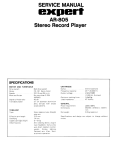
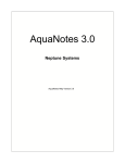
AquaController Apex Probe Module 3 Setup Guide Table of Contents PROBE MODULE 3 – INTRODUCTION .............................................................................. 1 FEATURES ...................................................................................................................... 1 PHYSICAL INSTALLATION .............................................................................................. 1 Initial Cconnections ............................................................................................................ 2 Startup ............................................................................................................................. 2 VERIFY THE INSTALLATION ........................................................................................... 2 UPDATE PROBE MODULE FIRMWARE .............................................................................. 3 DISSOLVED OXYGEN SETUP ........................................................................................... 3 Dissolved Oxygen Range ..................................................................................................... 3 DISSOLVED OXYGEN CALIBRATION ............................................................................... 4 DISSOLVED OXYGEN PROBE MAINTAINENCE ................................................................. 4 SWITCH INPUTS ............................................................................................................. 4 PROGRAMMING .............................................................................................................. 5 APENDIX 1 ..................................................................................................................... 6 Dissolved Oxygen Saturation Table....................................................................................... 6 Dissolved Oxygen/Altitude Compensation Table ..................................................................... 7 NEPTUNE SYSTEMS LIMITED WARRANTY ....................................................................... 8 PROBE MODULE 3 – INTRODUCTION Congratulations on your purchase of the AquaController Apex expansion accessory. The AquaController Apex Probe Module 3 expands the monitoring and control capabilities of your Apex system by adding a Dissolved Oxygen and temperature probe ports. The AquaController Apex System delivers an expandable, professional quality aquarium controller at hobbyist prices. The AquaController Apex is the most flexible, expandable system on the market today. FEATURES Monitor Dissolved Oxygen (D0). Control outlets based on the dissolved oxygen reading from the probe connected to the PM3. Automatic temperature compensation for DO with connected temperature probe (temperature probe optional). Monitor and control temperature with connected temperature probe (temperature probe optional). Galvanic Isolation for accurate and reliable probe readings. 6 digital inputs for float switches, water on the floor sensors, pressure sensors, etc. Full data logging and graphing through the Apex Base Module. The PM3 attaches to and is powered by the Apex system via AquaBus. Automatic Plug N Play for easy setup and configuration. Upgradeable firmware through AquaBus via the Apex Base Module. Multi-color LED Status Indicator. 2 AquaBus ports for flexible system connections. Comes with a 3' AquaBus cable. Compatible with Apex and Apex Lite systems. PHYSICAL INSTALLATION WARNING: Your Apex Base Module must be running firmware version 4.03 or higher to support the Probe Module 3. The current firmware version can be checked from the Apex Display on the Self Test screen. If needed, please upgrade the Apex Base Module firmware to 4.03 or higher before proceeding with the installation. See the Apex Setup and Programming Guide for firmware upgrade instructions. The AquaController Probe Module 3 should be securely mounted in a location free from moisture. Use wood screws through the mounting tabs of the probe module case or if mounting on drywall, use drywall anchors (mounting hardware not included). Mount all modules above the water line of the aquarium. Be sure to utilize drip loops on all power cords, AquaBus cables and probe cables. WARNING: Water damage will void your warranty! Mount all modules in locations safe from moisture exposure. The following precautions should be observed when installing the dissolved oxygen probe: The DO probe should not be located above air diffusers or in area with air bubbles in the water column. Air bubbles will cause erroneous readings. AquaController Apex Probe Module 3 - Setup Guide Page 1 The DO probe should be mounted with the membranes pointing up so that bubbles do not collect on the membrane surface. A cable tie can be used to secure the DO probe to its cable so that it hangs in membrane up orientation. The DO probe should be mounted in a location that has at least 3cm/sec of water movement. Figure 1 - Dissolved Oxygen Probe Mounting INITIAL CCONNECTIONS Plug one end of the included AquaBus cable into one of the AquaBus ports on the probe module and the other end into an available AquaBus port on your existing Apex system. It makes no difference which AquaBus port is used and you do not need to power down the system when connecting AquaBus accessories as the system is plug-and-play. WARNING: NEVER plug standard USB devices into any AquaBus connector or AquaBus accessories into computer USB ports. Damage to the AquaBus accessory and/or USB device may result. Connect the Dissolved Oxygen probe (must be purchased separately, available from your Neptune retailer) to the port labeled Dissolved Oxygen on the Probe Module 3. Push the Mini-DIN 6 connector into position paying close attention to the pin alignment. If you are using a temperature probe with the Probe Module 3 (must be purchased separately, available from your Neptune retailer), plug in to the port labeled Temp on the probe module and place the other end of the Temperature Probe in the aquarium water in an area of medium to high flow. WARNING: If temperature compensation is to be used on the PM3, a temperature probe must be connected and enabled on the PM3. The system temperature probe cannot be use for temperature compensation of a probe connected to a PM3. The temperature probe needs to be in the same area as the Dissolved Oxygen probe if temperature compensation is to be used. STARTUP As soon as the probe module is connected to an active AquaBus, the probe module will power up and begin to initialize. When first connected to an AquaController Base Module (through the AquaBus), the probe module will automatically be assigned an AquaBus address and be added to the AquaController configuration. The LED Status indicator on the probe module will flash yellow while it is being initialized. Once initialized, the LED Status indicator will be solid green. The LED Status indicator will flash yellow when the probe module is powered on and communication with the AquaController Base Module is lost. VERIFY THE INSTALLATION AquaController Apex Probe Module 3 - Setup Guide Page 2 Verify the probe module was initialized and added to the AquaController Apex configuration: Apex Display: Setup – Module Setup – Modify Name – from this screen, you can see all AquaBus modules installed on the system. Web Interface: Configuration – Module Setup – Verify the probe module is listed in the Apex Module List. UPDATE PROBE MODULE FIRMWARE A new version of firmware for probe modules may be included with Apex Base Module firmware updates. You should check the firmware version status when the probe module is first installed and after updating the AquaController Base Module firmware. See the section titled Updating Firmware in the AquaController Apex Setup and Programming Guide for instructions to update AquaController Apex Base Module and probe module firmware. To check or update an Apex module firmware: Apex Display: Setup – Module Setup – Update Module – use the up/down arrows to highlight the Apex module to update, push Select to update. Web Interface: Configuration – Module Setup – in the Module Configure area, in the Module: box, select the Apex module to update from the dropdown list, click the Update Firmware radio button, click the Submit Module Update button, a new browser window will open to display the update status. DISSOLVED OXYGEN SETUP To enable the Dissolved Oxygen probe: Apex Display: Setup – DO Setup – DO Enable – If you have more than one Dissolved Oxygen port on your system, use the up/down arrow keys to choose the port you wish to configure, press Select, then use the up/down arrow keys to select on/off for that port, press Save when done or Exit to discard changes. Web Interface: This option is not available from the Web Interface. In order for the Dissolved Oxygen probe to read correctly, the altitude of the probe must be set. To set the altitude of your system: Apex Display: Setup – DO Setup – Altitude – use the up/down arrow keys to set your system altitude to the nearest 100 feet, press OK when done or Exit to discard changes. Web Interface: This option is not available from the Web Interface. In order for the Dissolved Oxygen probe to read correctly, the salinity of your system must be entered. To set the salinity of your system: Apex Display: Setup – DO Setup – Salinity – use the up/down arrow keys to set your system salinity, press OK when done or Exit to discard changes. Web Interface: This option not available from the Web Interface. DISSOLVED OXYGEN RANGE The PM3 supports 2 dissolved oxygen ranges as described in Table 1 - Dissolved Oxygen Range Options. NOTE: If the dissolved oxygen range is changed, don’t forget to update outlet programs that are based on the dissolved oxygen reading as the values will change with the change in range. Range Units Description AquaController Apex Probe Module 3 - Setup Guide Page 3 SAT 0 to 200% PPM 0.0 to 20.0 ppm Percent of dissolved oxygen in the water column. 100% indicates a saturated DO level. The parts/million of oxygen in the water column. Table 1 - Dissolved Oxygen Range Options To set the Dissolved Oxygen range: Apex Display: Setup – DO Setup – DO Range – use the up/down arrow keys to choose the range, press OK when done or Exit to discard changes. Web Interface: This option is not available from the Web Interface. DISSOLVED OXYGEN CALIBRATION NOTE: Set the Dissolved Oxygen Range, system Altitude and Salinity before calibrating the Dissolved Oxygen probe. See the previous section for instructions on setting these parameters. To calibrate a Dissolved Oxygen probe: Apex Display: Setup – DO Setup – DO Calibrate – 1. If you have more than one Dissolved Oxygen probe enabled in your system, use the up/down arrow keys to choose the probe you wish to calibrate, press Select. 2. Plug the Dissolved Oxygen Zero adapter into the DO port on the PM3. Wait for the numbers on the bottom of the LCD screen to stop changing. It does not matter what value is displayed only that it is not changing. When the display stops changing press the select button. 3. Unplug the DO Zero Adapter and plug in the DO probe into the DO port on the PM3. Take the DO probe out of water and dry the membrane. Allow 10 minutes for the probe to reach temperature equilibrium. Do not place probe in direct sunlight. 4. Wait for the numbers on the bottom of the LCD screen to stop changing. When the display stops changing press the select button. 5. The dissolved probe should now be properly calibrated. Web Interface: This option not available from the Web Interface. DISSOLVED OXYGEN PROBE MAINTAINENCE Dissolved Oxygen probes should be kept clear of any organic matter. Gently wipe the probe with a soft cloth to keep clean. SWITCH INPUTS The PM3 has a Mini DIN8 connector for switch inputs labeled I/O. These inputs can be used for switches, float switches, water sensors, flow sensors, etc. Switch inputs connected to probe modules will be identified as Swx3_2, Swx5_3, etc. The first number in the switch name corresponds to the AquaBus address assigned to the probe module. The second number corresponds to the switch input number (1 - 6). WARNING: Do not apply voltage to the switch inputs or damage to the AquaController Apex may occur. The pin-out of the connector is shown in Figure 2 - Switch Input Connector. Connect switches to the AquaController Apex by connecting one wire from the mechanical switch to the ground pin (pin 8), and the AquaController Apex Probe Module 3 - Setup Guide Page 4 other wire from the switch to one of the six digital inputs (pin 1-6). Connections can be easily made using a Neptune I/O Breakout box available at your local Neptune Retailer. The breakout box features spring loaded connectors to make connections easy without tools or soldering. The Apex and accessory inputs are TTL level (5V) inputs with internal pull-up resistors. With nothing connected, the switch inputs will indicate OPEN (Logic 1 - 5V). When connected to Ground (Pin 8) the switch will indicate CLOSED (Logic 0 - 0V). Figure 2 - Switch Input Connector Pin Number Description 1 Input 1 2 Input 2 3 Input 3 4 Input 4 5 Input 5 6 Input 6 7 Reserved 8 Ground Table 2 – Switch Input Connector Pin-out Switch Inputs are programmed using the If Switch command. For example, if you wanted to turn a pump on when a float switch closes, you would add this command to the pump outlet program: If Switch1 CLOSED Then ON See the section titled Appendix 3 – Programming Reference and Appendix 4 – Advanced Programming Examples in the Apex Setup and Programming Guide for more information. PROGRAMMING Dissolved Oxygen probes connected to probe modules will be identified as “DOx3”, “DOx4”, and so on. The number in the probe name corresponds to the AquaBus address assigned to the probe module. If a temperature probe is connected to the probe module, it is identified as “Tmpx3”, “Tmpx4”, etc. with the same AquaBus number as the conductivity probe. Switch inputs connected to probe modules will be identified as Swx3_2, Swx5_3, etc. The first number in the switch name corresponds to the AquaBus address assigned to the probe module. The second number corresponds to the switch input number (1 - 6). NOTE: The Dissolved Oxygen reading can be added to the Apex Display and Web Interface Status Screens. See the section titled Display Setup in the Apex Setup and Programming Guide for more information. AquaController Apex Probe Module 3 - Setup Guide Page 5 The following are some valid program statements (assumes that probe module is installed and configured on AquaBus address 4). If Tmpx4 > 80.0 Then ON If DOdx4 > 99 Then ON If Swx4_2 CLOSED Then OFF Please see the Programming Outlets section of the Apex Setup and Programming Guide for more information on programming the AquaController Apex. APENDIX 1 DISSOLVED OXYGEN SATURATION TABLE Solubility of oxygen in water exposed to water-saturated air at atmospheric pressure (760mm Hg). This table is not required to calibrate the PM3 and is provided for information purposes only. Temperature Salinity (ppt) F C 0 5 10 15 20 25 30 35 40 45 50 51 52 53 54 55 56 57 58 59 60 61 62 63 64 65 66 67 68 69 70 71 72 73 74 75 76 77 78 79 10.0 10.6 11.1 11.7 12.2 12.8 13.3 13.9 14.4 15.0 15.6 16.1 16.7 17.2 17.8 18.3 18.9 19.4 20.0 20.6 21.1 21.7 22.2 22.8 23.3 23.9 24.4 25.0 25.6 26.1 11.29 11.14 11.00 10.86 10.72 10.59 10.46 10.33 10.21 10.08 9.96 9.85 9.73 9.62 9.51 9.40 9.30 9.19 9.09 8.99 8.90 8.80 8.71 8.61 8.52 8.44 8.35 8.26 8.18 8.10 10.93 10.79 10.66 10.52 10.39 10.26 10.14 10.02 9.90 9.78 9.66 9.55 9.44 9.33 9.23 9.13 9.02 8.93 8.83 8.73 8.64 8.55 8.46 8.37 8.28 8.20 8.11 8.03 7.95 7.87 10.59 10.45 10.32 10.20 10.07 9.95 9.83 9.71 9.60 9.48 9.37 9.27 9.16 9.06 8.96 8.86 8.76 8.66 8.57 8.48 8.39 8.30 8.22 8.13 8.05 7.97 7.89 7.81 7.73 7.65 10.26 10.13 10.00 9.88 9.76 9.64 9.53 9.41 9.30 9.20 9.09 8.99 8.89 8.79 8.69 8.60 8.50 8.41 8.32 8.23 8.15 8.06 7.98 7.90 7.82 7.74 7.66 7.59 7.51 7.44 9.93 9.81 9.69 9.57 9.46 9.35 9.24 9.13 9.02 8.92 8.82 8.72 8.62 8.53 8.43 8.34 8.25 8.17 8.08 8.00 7.91 7.83 7.75 7.67 7.60 7.52 7.45 7.38 7.30 7.23 9.62 9.50 9.39 9.28 9.17 9.06 8.95 8.85 8.75 8.65 8.55 8.46 8.37 8.27 8.19 8.10 8.01 7.93 7.85 7.76 7.69 7.61 7.53 7.46 7.38 7.31 7.24 7.17 7.10 7.03 9.32 9.21 9.10 8.99 8.88 8.78 8.68 8.58 8.48 8.39 8.30 8.21 8.12 8.03 7.94 7.86 7.78 7.70 7.62 7.54 7.46 7.39 7.32 7.24 7.17 7.10 7.03 6.97 6.90 6.84 9.02 8.92 8.81 8.71 8.61 8.51 8.41 8.32 8.23 8.14 8.05 7.96 7.87 7.79 7.71 7.63 7.55 7.47 7.40 7.32 7.25 7.18 7.11 7.04 6.97 6.90 6.84 6.77 6.71 6.65 8.74 8.64 8.54 8.44 8.34 8.25 8.16 8.06 7.98 7.89 7.80 7.72 7.64 7.56 7.48 7.40 7.33 7.25 7.18 7.11 7.04 6.97 6.90 6.84 6.77 6.71 6.64 6.58 6.52 6.46 8.47 8.37 8.27 8.18 8.08 7.99 7.91 7.82 7.73 7.65 7.57 7.49 7.41 7.33 7.26 7.19 7.11 7.04 6.97 6.90 6.84 6.77 6.71 6.64 6.58 6.52 6.46 6.40 6.34 6.28 AquaController Apex Probe Module 3 - Setup Guide Page 6 Temperature Salinity (ppt) F C 0 5 10 15 20 25 30 35 40 45 80 81 82 83 84 85 86 87 88 89 90 91 92 93 94 95 96 97 98 99 100 101 102 103 104 105 106 107 108 109 110 111 112 113 26.7 27.2 27.8 28.3 28.9 29.4 30.0 30.6 31.1 31.7 32.2 32.8 33.3 33.9 34.4 35.0 35.6 36.1 36.7 37.2 37.8 38.3 38.9 39.4 40.0 40.6 41.1 41.7 42.2 42.8 43.3 43.9 44.4 45.0 8.02 7.94 7.86 7.78 7.71 7.63 7.56 7.49 7.42 7.35 7.28 7.21 7.14 7.08 7.01 6.95 6.89 6.82 6.76 6.70 6.64 6.58 6.53 6.47 6.41 6.36 6.30 6.25 6.19 6.14 6.09 6.03 5.98 5.93 7.79 7.72 7.64 7.57 7.50 7.42 7.35 7.28 7.22 7.15 7.08 7.02 6.95 6.89 6.83 6.77 6.71 6.65 6.59 6.53 6.47 6.42 6.36 6.30 6.25 6.20 6.14 6.09 6.04 5.99 5.93 5.88 5.83 5.78 7.58 7.50 7.43 7.36 7.29 7.22 7.15 7.09 7.02 6.96 6.89 6.83 6.77 6.71 6.65 6.59 6.53 6.47 6.42 6.36 6.30 6.25 6.20 6.14 6.09 6.04 5.99 5.94 5.89 5.84 5.79 5.74 5.69 5.64 7.37 7.30 7.23 7.16 7.09 7.03 6.96 6.90 6.83 6.77 6.71 6.65 6.59 6.53 6.47 6.42 6.36 6.30 6.25 6.20 6.14 6.09 6.04 5.99 5.93 5.88 5.83 5.79 5.74 5.69 5.64 5.59 5.55 5.50 7.16 7.10 7.03 6.96 6.90 6.84 6.77 6.71 6.65 6.59 6.53 6.47 6.42 6.36 6.30 6.25 6.19 6.14 6.09 6.04 5.98 5.93 5.88 5.83 5.78 5.74 5.69 5.64 5.59 5.55 5.50 5.45 5.41 5.37 6.97 6.90 6.84 6.77 6.71 6.65 6.59 6.53 6.47 6.41 6.36 6.30 6.25 6.19 6.14 6.08 6.03 5.98 5.93 5.88 5.83 5.78 5.73 5.68 5.64 5.59 5.54 5.50 5.45 5.41 5.36 5.32 5.28 5.23 6.77 6.71 6.65 6.59 6.53 6.47 6.41 6.35 6.30 6.24 6.19 6.13 6.08 6.03 5.98 5.92 5.87 5.82 5.78 5.73 5.68 5.63 5.58 5.54 5.49 5.45 5.40 5.36 5.31 5.27 5.23 5.19 5.14 5.10 6.58 6.52 6.47 6.41 6.35 6.29 6.24 6.18 6.13 6.07 6.02 5.97 5.92 5.87 5.82 5.77 5.72 5.67 5.63 5.58 5.53 5.49 5.44 5.40 5.35 5.31 5.27 5.22 5.18 5.14 5.10 5.06 5.02 4.98 6.40 6.34 6.29 6.23 6.18 6.12 6.07 6.01 5.96 5.91 5.86 5.81 5.76 5.71 5.66 5.62 5.57 5.52 5.48 5.43 5.39 5.35 5.30 5.26 5.22 5.17 5.13 5.09 5.05 5.01 4.97 4.93 4.89 4.85 6.23 6.17 6.11 6.06 6.01 5.95 5.90 5.85 5.80 5.75 5.70 5.66 5.61 5.56 5.52 5.47 5.42 5.38 5.34 5.29 5.25 5.21 5.17 5.12 5.08 5.04 5.00 4.96 4.92 4.88 4.85 4.81 4.77 4.73 DISSOLVED OXYGEN/ALTITUDE COMPENSATION TABLE This table shows relationship between solubility of dissolved oxygen and altitude. This table is not required to calibrate the PM3 and is provided for information purposes only. Height Pressure Comp Meters Feet kPA In of Hg mm of Hg Atm Factor 0 242 485 0 795 1591 101.3 98.8 96.2 29.9 29.2 28.4 760 741 722 1.000 0.975 0.950 1.00 0.97 0.95 AquaController Apex Probe Module 3 - Setup Guide Page 7 727 970 1212 1455 1697 1940 2182 2424 2667 2909 3152 2386 3182 3977 4772 5568 6363 7159 7954 8750 9545 10340 93.7 91.2 88.6 86.1 83.6 81.0 78.5 76.0 73.4 70.9 68.4 27.7 26.9 26.2 25.4 24.7 23.9 23.2 22.4 21.7 20.9 20.2 703 684 665 646 627 608 589 570 551 532 513 0.925 0.900 0.875 0.850 0.825 0.800 0.775 0.750 0.725 0.700 0.675 0.92 0.90 0.87 0.85 0.82 0.80 0.77 0.75 0.72 0.70 0.67 NEPTUNE SYSTEMS LIMITED WARRANTY Neptune Systems warrants this product to be free from defects in material and workmanship for a period of 1 year from the date of purchase. Probes carry a 90-day warranty. If repair or adjustment is necessary and has not been the result of abuse, misuse, or accidental damage, within the 1-year period, please return the product with proof of purchase, and correction of the defect will be made without charge. For your protection, items being returned must be carefully packed to prevent damage in shipment and insured against possible damage or loss. Neptune Systems will not be responsible for damage resulting from careless or insufficient packaging. Before returning please obtain a return authorization (RMA) number from Neptune Systems at (408) 578-3022. Returned merchandise will not be accepted without a RMA number. Except for the warranty set forth above, Neptune Systems is not responsible for any damages including, but not limited to, consequential damage occurring out of or in connection with the delivery, use or performance of Neptune Systems’ products. Buyer’s remedies for breach of warranty shall be limited to repair, or replacement and full or partial adjustment to purchase price. 105 Cochrane Circle, Suite L Morgan Hill, CA 95037 http://www.neptunesys.com [email protected] Phone 408-779-4090 Fax 408-762-2042 ©2013 Neptune Systems - All Rights Reserved PM3 Manual V3 AquaController Apex Probe Module 3 - Setup Guide Page 8 CE DECLARATION OF CONFORMITY Manufacturer: Neptune Systems, LLC. 105 Cochrane Circle Suite L, Morgan Hill, CA 95037; 408-779-4090 Product: Dissolved Oxygen, Temperature, I/O Expansion Module Model No. PM3 The undersigned hereby declares, on behalf of the Neptune Systems, LLC. of Morgan Hill, California that the abovereferenced product, to which this declaration relates, is in conformity with the provisions of: EN 60950-1+A1:2009 EN 60335-1:2010 The Technical Construction File required by this Directive is maintained at the corporate headquarters of Neptune Systems, LLC, 105 Cochrane Circle, Suite L, Morgan Hill, California. ________________________ Curt Pansegrau President The symbol to the right means that according to local laws and regulations your product should be disposed of separately from household waste. When this product reaches its end of life, take it to a collection point designated by local authorities. Some collection points accept products for free. The separate collection and recycling of your product at the time of disposal will help conserve natural resources and ensure that it is recycled in a manner that protects human health and the environment. AquaController Apex Probe Module 3 - Setup Guide Page 9