1
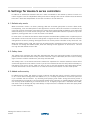
English
Asema S2
User Manual
Asema S2: User Manual
Asema Electronics Ltd
Copyright © 2011-2013
No part of this publication may be reproduced, published, stored in an electronic database, or transmitted, in any form or by any means,
electronic, mechanical, recording, or otherwise, for any purpose, without the prior written permission from Asema Electronics Ltd.
Asema E is a registered trademark of Asema Electronics Ltd.
Table of Contents
Safety ..........................................................................................................................................
1. Installation considerations ........................................................................................................
1.1. Choosing the appliances to control ................................................................................
1.2. Controlling large multi-phase loads with contactors ........................................................
2. Installation to a distribution box ...............................................................................................
3. Pairing and communicating with Asema E .................................................................................
3.1. Detecting, pairing and naming controllers on the device. .................................................
3.2. Detecting, pairing and naming controllers using the WebView. ........................................
3.3. Radio quality measurement ...........................................................................................
3.3.1. Radio quality measurement on the device ...........................................................
3.3.2. Radio quality measurement in the WebView ........................................................
3.4. Removing the controller ................................................................................................
3.4.1. Removing the controller on the device ................................................................
3.4.2. Removing the controller in WebView. ..................................................................
3.5. Resetting the controller .................................................................................................
3.6. Mesh networking and repeaters ....................................................................................
4. Settings for Asema S series controllers ....................................................................................
4.1. Default relay mode ........................................................................................................
4.2. Safety timer ..................................................................................................................
4.3. Added radio security ......................................................................................................
5. Troubleshooting .......................................................................................................................
Asema S2
1
2
2
2
3
4
4
4
5
5
6
6
6
6
7
7
8
8
8
8
9
iii / 10
Safety
Please read this before proceeding and follow the safety precautions below when installing and operating
the system.
Retain and follow all product safety and operating instructions.
Observe all warnings in the operating instructions on the product.
Operate your appliances responsibly, especially when controlling them with remote controls or over the Internet. Remote control of appliances in an Asema system is disabled by default to prevent accidental damage.
Enable remote control only on devices where you can be certain damage cannot occur due to for instance
heat, fire, smoke or water you do not notice while not present.
Always use an authorized and qualified electrician when installing products that involve rewiring electrical
connections, changes to the distribution box, or opening wall sockets or other components embedded into
walls, floors, or ceilings. Live cables can only be accessed by a qualified electrician.
Do not force or bend the cables at any point during installation. Do not drop, throw or try to bend the
product. If you are worried or have any concerns about the installation, please contact a qualified electrician
immediately.
Slots and openings in the product are provided for ventilation. These openings must not be blocked or covered.
Loss of ventilation may cause the product to overheat.
If you notice anything unusual about the product such as loose wires, exposed cabling, burn marks, holes in
the insulating materials or damage to the product, stop immediately.
When a power supply unit is included with the product only use the designated power supply unit. Other
usage may be dangerous and will invalidate any approval given to this product.
Unless specifically indicated otherwise, the product is designed to operate in room temperature under dry
conditions. Keep the device dry and away from excessive moisture, water or any liquid as it may cause a
short circuit. Keep the device away from extreme temperatures.
If this product is equipped with a USB-port for connecting to a power or a computer, note that connecting
to improperly grounded equipment can result in an electric shock to your device. Be sure your computer is
properly grounded (earthed) before connecting this product to a computer.
Do not use this product in gas stations, fuel depots, chemical plants or where blasting operations are in
progress, or in potentially explosive atmospheres such as fueling areas, fuel storehouses, below deck on
boats, chemical plants, fuel or chemical transfer or storage facilities, and areas where the air contains chemicals or particles, such as grain, dust, or metal powders. Please be aware that sparks in such areas could cause
an explosion or fire resulting in bodily injury or even death.
This product may cause medical equipment to malfunction. The use of this device is forbidden in most hospitals and medical clinics.
There is no need to open the product. YOUR WARRANTY IS INVALIDATED IF YOU DISASSEMBLE OR ATTEMPT TO DISASSEMBLE THE DEVICE.
1. Installation considerations
1.1. Choosing the appliances to control
Asema S2 is a 16A relay controller and is suitable for controlling nearly any single-phase load found in
a normal household. Always ensure that you install the Asema S2 in series with a fuse to make sure
the rated current is not exceeded.
In case the electrical installation is originally designed properly, you should usually find proper appliances
or groups of appliances to control by analyzing the setup of fuses. Primary locations to control should
be lights and appliances that are difficult to reach by the residents and are therefore frequently left on
accidentally. Typical targets are also high-load appliances that can benefit from tariff controls, such as
washing machines and dryers.
Important
If the Asema S2 is used to measure or control an appliance that needs electrical
supply after a purposeful or accidental blackout, such as a refrigerator or freezer,
the default power supply mode should be switched from its factory setting OFF
to ON. For more information, please see chapter 4.1, “Default relay mode”.
1.2. Controlling large multi-phase loads with contactors
An Asema S2 can also be used to control a three-phase load with the help of a contactor. In this case
choose a contactor model with a connector to an external switch and connect the Asema S2 to this
connector. Let the contactor itself switch the actual loads.
As the current will run through the connector, Asema S2 cannot accurately measure the power consumption of the load. To enable power consumption measurement in this case you can either
1. Install an Asema M2 to measure the phases. This will give you an accurate measure of all the power
consumption.
2. Assign a power multiplier to the Asema S2. If the Asema S2 measures some power that goes through
to the connector, this can be multiplied in software to give and indication of consumed power. The
measurement is not accurate, especially if the relation between the control current and the actual
load is not linear but does give feedback on a device consuming power.
RESET
230V~ 50Hz
16A
2
Installation considerations
2 / 10
2. Installation to a distribution box
The S2 can be installed directly into your electricity distribution panel, enabling control and measure of
entire groups at once.
1. Switch off mains power of the panel.
2. Locate the fuse (max 16A) protecting the targeted appliance or group.
3. Connect Asema S2 to the load in series after the fuse by attaching incoming and outgoing neutral
and phase.
Installation to a distribution box
3 / 10
3. Pairing and communicating with Asema E
In order for the Asema E to communicate with the Asema controllers, they need to be paired first. After
pairing the Asema E can send ON/OFF messages to the controllers and read real-time information on
the electricity use. Pairing can be done either using the device, or in the WebView.
3.1. Detecting, pairing and naming controllers on the device.
1. On the Asema E, go to Main Setup > Appliances > Appliances.
2. Click “Detect”. The Asema E will now scan all Asema controllers which are not yet paired, and list
them on the screen. This can take a few seconds.
3. The result will be list of controllers, looking like this:
The controllers don't have a name yet, just a code on the top, which corresponds with the sticker that
you received with your controller. To distinguish which controller is which, you can either compare the
displayed code to the sticker or click on the sound icon (top-button). The controller will beep, which
will help you in recognizing which controller you are currently adding.
4.
Click on the gear icon
(middle button) to edit the controller. Fill in a name for the controller that
will help you distinguish it. We recommend naming it after the appliance you will connect to it. From
the drop-down menu choose an appliance type.
5. Click OK. The controller will now be saved and you will be returned to the list of controllers, including
the unpaired ones. Repeat step 4-5 for all unpaired controllers until all controllers are paired.
6. You're done! The controller will now also automatically be added to the ON/OFF, Power Consumption
History, and Power Meter screenlets of an Asema E and appear there when you run these.
3.2. Detecting, pairing and naming controllers using the WebView.
1. Go the the WebView. You do this by typing in the IP address of your device into a browser on your
computer. You can find the IP address either in Main Setup, or by clicking on the black status bar at
the top in the E-view. Once the application is loaded in your browser, click on Appliances. This will
open up the Appliances page. If this is the first time you add a controller, the page will be almost
empty. If you have added controllers before, they will be listed here.
2. Click “Detect”. The Asema E will now scan all Asema controllers which are not yet paired, and list
them on the screen. This can take a few seconds.
3. The result will be list of controllers, looking like this:
Pairing and communicating with
Asema E
4 / 10
Pairing and communicating with Asema E
The controllers don't have a name yet, just a code on the top, which corresponds with the sticker that
you received with your controller. To distinguish which controller is which, you can either compare the
displayed code to the sticker on the controller, or click on the sound icon (top-button). The controller
will beep, which will help you in recognizing which controller you are currently adding.
4.
Click on the gear icon
(middle button) of the controller you want to pair. This will open up a
form. Fill in a name for the controller that will help you distinguish it. We recommend naming it after
the appliance you will connect to it.
5. Click OK. The controllers will now be saved and you will be returned to the list of controllers, including
the unpaired ones. Repeat step 4-5 for all unpaired controllers until all controllers are paired.
6. You're done. The controllers will now also automatically be added to the ON/OFF, Power Consumption History, and Power Meter screenlets of an Asema E, and appear there when you run these.
3.3. Radio quality measurement
The Asema controller communicates with the Asema E device through radio signals on 434 MHz frequency. If your system is having problems, such as the buttons not switching ON or OFF appliances
when you click on them, it might be that there are some problems with the radio signal. In certain installations or buildings the radio signal gets interference either from other signals, or due to the nature
of the building, such as for example, thick steel walls. The Asema E can diagnose the radio quality.
3.3.1. Radio quality measurement on the device
1. Go to Main Setup > Appliances > Controllers. This will list all the controllers you have paired with
the device. At the end of each Asema controller listed, you will see the test icon below
. Tap on it.
1. This will send a test message to all controllers which will test the radio quality. It will return 4 values:
· Device identifier: This is simply the ID of the controller in your system.
· Signal quality: This shows a value between 1 and 100. On average a good working connection
should show between 50 and 70.
· Packet loss: the percentage of data packages that is lost in transmission. This value should not
be more than 10.
Pairing and communicating with
Asema E
5 / 10
Pairing and communicating with Asema E
· Hop count: the Asema E system can send messages to one controller that is far away, using
another controller that is closer. The message then 'hops' from one controller to another and the
same way back. In this way the distance a radio message is increased significantly. The maximum
number of hops is four. For optimal performance you should try to get a hop count below three
(See also Section 3.6 Mesh Networking).
3.3.2. Radio quality measurement in the WebView
1. Go to WebView > Appliances > Controllers. This will list all the controllers you have paired with the
device. At the end of each Asema controller listed, you will see an icon labeled "QA". Tap on it:
2. This will send a test message to all controllers which will test the radio quality. It will return 4 values,
which you will see in the pop-up:
· Device identifier: This is simply the ID of the controller in your system.
· Signal quality: This shows a value between 1 and 100. On average a good working connection
should show between 50 and 70.
· Packet loss: the percentage of data packages that it lost during transmission. This should not be
more than 10.
· Hop count: the Asema E system can send messages to one controller that is far away, using
another controller that is closer. The message then 'hops' from one controller to another and the
same way back. In this way the distance a radio message is increased significantly. The maximum
number of hops is four. You should try to get reading under three for optimal performance (See
also Section 3.6 Mesh Networking)
3.4. Removing the controller
To remove or unpair a controller, follow the following steps.
3.4.1. Removing the controller on the device
1. Go to Main Setup > Appliances > Appliances. This will list all the connected appliances and their
controllers.
2. Click on the gear icon of the appliance you want to remove. This will open up a form with all the
settings for this controller.
3. Click on "Delete". It will give you a pop-up, asking if you are sure that you want to remove this appliance. Click on OK. You will then get a second pop-up, asking if you would also like to remove the
controller. Click OK.
4. You will then see the device processing the data. You will be notified when the appliance has been
removed, and when the controller has been reset.
5. The controller is now removed from the system, reset and can be paired again with any Asema E
system. When you click on Detect, it will immediately detect the unpaired controller.
3.4.2. Removing the controller in WebView.
1. Go to WebView, and click on Appliances. This will list all the connected appliances.
2. Click on the gear icon of the appliance you want to remove. This will open up a form with all the
settings for this controller.
Pairing and communicating with
Asema E
6 / 10
Pairing and communicating with Asema E
3. Click on "Delete". It will give you a pop-up, asking if you are sure that you want to remove this appliance. Click on OK. You will then get a second pop-up, asking if you would also like to remove the
controller. Click OK.
4. You will then see the browser processing the data. You will be notified when the appliance has been
removed, and when the controller has been reset.
5. The controller is now removed from the system, reset and can be paired again with any Asema E
system. When you click on Detect, it will immediately detect the unpaired controller.
3.5. Resetting the controller
Each Asema S series device has a dedicated reset button for removing pairing data from the controller
itself manually. You should always try to reset a control from the Asema E first before doing a manual
reset.
A manual reset will simply remove the pairing from the controller without telling about this to an Asema
E. It will therefore result in a "ghost" controller on the Asema E that can no longer be reached. You can
however remove the ghost controller with a forced delete on the Asema E. Please refer to Asema E
manual for more information.
The manual reset is needed if you have lost pairing data on your Asema E due to replaced equipment,
accidental deletion or other similar reason. To perform the manual reset, you must have the controller
connected to mains power. Then simply press the reset button. The controller will beep as an indication
of reset.
You can find the reset button as follows
· On an Asema S1, the reset button is the transparent button with blinking red LED light
· On an Asema S2, the reset button is the gray button in front, marked with "RESET"
· On an Asema S3, the reset button is the transparent button with blinking red LED light, found under
the top cover of the device
3.6. Mesh networking and repeaters
Mesh networking means that controllers with a radio can relay messages automatically between them
and this way extend the range of communication or go around obstacles. Thus they work automatically
as repeaters of messages for each other. Asema S series controllers and Asema M series meters can
automatically form a mesh network.
You do not have to do anything to enable mesh networking, the devices will do this automatically.
However, you may benefit from knowing the topology of the mesh network as placing a controller
between two controllers that have trouble communicating with each other may improve the situation.
To get most out of mesh networking, take a look at the radio quality signals of the controllers. Read
3.3, “Radio quality measurement” to see how this is done. The "Hop count" measure tells you how many
repeaters are between the Asema E and the controller you are analyzing. If you see a low hop count but
a bad radio quality, this means that the radio is suffering from disturbance due to distance or obstacles.
Placing another controller in a location that is between the two devices, possibly so that it allows to
bypass an obstacle, will improve your installation.
Pairing and communicating with
Asema E
7 / 10
4. Settings for Asema S series controllers
In addition to automation features that work when connected to the Asema E, Asema S series controllers support a set of independent safety and control settings that can be modifies with the Asema
E but work after that independent of the radio connection to the Asema E.
4.1. Default relay mode
When an Asema S series is in factory settings, after the controller gets power it will be in OFF mode.
Consequently, it will not feed power to the appliance it controls unless the controller is switched on by
using the controls of Asema E. The reason for having power switched OFF by default is fire safety and
electrical safety. If for some reason during a blackout easily flammable material is placed on top of an
appliance, turning power back on will not cause a fire hazard.
In some cases it is however desirable to have the power switched ON by default. This is especially true if
the Asema S series controller controls a refrigerator or digital recorder. If the default mode has not been
changed from its factory setting, the appliance will not receive power even after a very short blackout.
When the default mode is ON, the power will be automatically switched on when power returns to the
controller. To change the default mode, enter the settings of the appliance in case and tick the box
marking that the default mode is ON.
4.2. Safety timer
The safety timer switches the relay OFF automatically after the configured number of seconds has
passed since the last ON switch. Every time the controller is put to ON state, the timer starts counting
again. Once the counter reaches zero, the relay switches OFF.
The safety timer is a convenient and secure method to implement for instance automatic switch off of
such home appliances as an electric stove. If you are worried that the stove if easily left accidentally on,
the Asema S will turn it off e.g. after one hour of use. In case the appliance uses three-phase power,
connect the Asema S series controller to a contactor and let the contactor cut the actual power.
4.3. Added radio security
In added security mode, the Asema S series controller will add and require a specific random security
token in each radio message. With the added token, it is virtually impossible for a malicious person to
try to interfere with the network by recording and replaying radio traffic. Using the security token is
recommended if you operate in an environment where extra protection is needed. Because setting up
this security while establishing a communication link takes slightly longer than in standard radio traffic,
the mode is off by default and may cause delays in response time in installations where the input power
to the Asema S is cut regularly.
Settings for Asema S series controllers
8 / 10
5. Troubleshooting
This section lists a few common problems you may encounter into while using your controller and
common remedies to them. For a more complete list of howto's and up-to-date answers to problems,
visit the FAQ section on our support website at support.asema.com.
· Cannot detect a controller
If a controller cannot be found when detecting a controller, the problem can be the cause of four
basic reasons: 1) the controller is not connected to mains power, 2) the radio reception is poor, 3) the
controller is already paired, or 4) the device is broken.
First make sure the controller is properly connected. On Asema S1, the LED light will blink to indicate
a proper mains connection. On Asema S3, when power on pressing the foot switch will cause a tick
sound when the relay switches on.
After making sure you have power, make sure there are no interfering obstacles between the controller and an Asema E and the distance between the two does not exceed 30 meters.
Make sure that the controller is not already paired. A paired controller no longer sends a beacon
and cannot therefore be detected. To have the controller send beacon again, reset it either from the
Asema E (in case of a controller paired to that Asema E) or from the reset button.
· Cannot pair a controller
Pairing a controller requires a good radio connection between the controller and Asema E. Make
sure you have no interfering elements between the devices and the distance is short enough. For
troubleshooting purposes you may want to move your Asema E closer to the controller to see how
distance affects the radio connection. Use the bar indicators to check the field strength if necessary.
· Slow response to commands
If your controller works but the operation seems sluggish, this is most likely due to poor radio coverage. The commands are slow because they need to be resent many times before a valid command
can be pushed through.
To improve the response, you may want to place the devices differently to avoid radio disturbance.
Placing another controller in between the devices may also help as a repeater. Note also that radio
antennas are always directional to some directions and reflections from walls and other structures
will affect the way radios work. Try to move or rotate your Asema E a bit, this may help the radio
connection considerably.
Troubleshooting
9 / 10
Recycling
At the end of its serviceable life, this product should not be treated as household or general waste. It should be
handed over to the applicable collection point for recycling of electrical and electronic equipment, or returned
to the supplier for disposal. You are liable to dispose of all your electronic or electrical waste equipment by
relocating over to the specified collection point for recycling of such hazardous waste. Isolated collection and
proper recovery of your electronic and electrical waste equipment at the time of disposal will allow us to help
conserving natural resources. Moreover proper recycling of the electronic and electrical waste equipment will
ensure safety of human health and environment.
RoHS compliance. This product is in compliance with Directive 2002/95/EC of the European Parliament and
of the Council of 27 January 2003, on the restriction of the use of certain hazardous substances in electrical
and electronic equipment (RoHS) and its amendments.
For full compliance statements, please visit www.asema.com.
Recycling
10 / 10