1
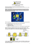
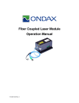
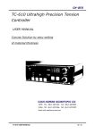
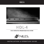
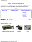
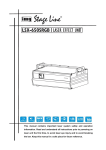
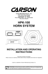
Laser Safety Systems User Manual Revision 4.1 July 2015 This manual is available on-line at: http://www.lasersafetysystems.com/files/Laser_Safety_Systems_user_manual.pdf Table of Contents Section 1.0 Introduction 1.1 1.2 2.0 2.1 2.2 2.3 2.4 3.0 3.01 3.02 3.03 3.04 3.05 3.06 3.07 4.0 5.0 6.0 7.0 8.0 General Description Safety Warning System Installation Wiring Concept Start and End Nodes System Power Requirements Conduit and Box Selection Interlock Module Descriptions LSS-2380 Laser Warning Module LSS-2381 Interlock Control Module LSS-2383 Emergency Crash Module LSS-2384 Laser / Shutter Interface Module LSS-2387 Non-Defeatable Access Monitor LSS-2387B Non-Defeatable Access Monitor LSS-2388 Defeatable Access Control Kit System Troubleshooting Periodic Performance Test Procedure Module Cleaning Procedure Warranty Return Material Authorization Procedures Laser Safety Systems user manual revision 4.0 July 2015 Page 2 2 2 2 2 3 3 3 4 4 5 6 6 8 9 9 9 12 13 13 13 1 1.0 Introduction Thank you for purchasing the Laser Safety Systems - 2380 Series Laser Interlock system. The system has been designed for long service life maintenance-free operation. All interlock functions utilize redundant trip circuitry and are designed for fail-safe fault tolerance. Please review the following chapters prior to operation of the system. 1.1 General Description The LSS-2380 Series Laser Interlock system is a collection of modules that are designed to work in a series chain. Each control module in the chain has complete knowledge of the interlock status. If a module has an interlock “crash” function, it will have the ability to secure the system regardless of its position within the chain. This method allows simple expansion of the system as the needs of the user grow. 1.2 Safety Warning WARNING The use of the LSS-2380 Series Laser Interlock system or any other type of engineered access control does not reduce or eliminate any of the other required elements of Laser Safety (i.e. Laser Protective Eyewear) specified in ANSI Z136.12007, or any other applicable standard. Periodic verification of all functions of the interlock system is required to ensure proper operation. This verification should be performed every six months for most industrial settings. The verification should be performed at the beginning of each semester in an educational setting. 2.0 System Installation Proper installation is critical to safe and reliable operation and should be performed by a licensed electrician. A lab specific schematic diagram will be provided with a system purchase. 2.1 Wiring Concept Separate modules can be placed in series to form a complete operational system. The modules can be placed in any order to form a complete system, but they must be wired in “series” and must be terminated with a “start” and “end” termination. Example: The main cable used to wire all modules together is 20 AWG, 8 conductor, stranded wire type with eight distinct colors. Our standard wiring for terminal strips X1 and X2 follows: 1-BLACK 2-BROWN 3-RED 4-ORANGE 5-YELLOW 6-GREEN, 7-BLUE 8-WHITE Laser Safety Systems user manual revision 4.0 July 2015 2 2.2 Start / End Nodes Provided with every system purchase, the start and end nodes are simply wire jumpers on the X1 and X2 terminals that loop back control power through the interlock cable. We could have simply instructed the installer to jumper one end 6 to 1 and the other end 1 to 2, but there is less confusion when the jumpers are pre-made. 2.3 System Power Requirements Power is supplied to the interlock system by a 24 VDC UL/CE rated power supply with 1 Amp capacity. The RED terminated wire is +24V and the green wire is a common return. The client also has the choice of providing their own power, as long as it meets the 24VDC and minimum 1 amp capacity. Power is introduced via the surface mounted box containing the laser table interlock relay module (LSS2384). This location was chosen because the module also has exiting wires for the interlock connection to the laser power supply or shutter controller. A room may have multiple interlock relay modules, however it is only necessary to introduce system power at a single point. The input is fused with a PTC fuse that will automatically reset when the fault condition has been corrected. A specialized cord grip is provided with the LSS2384 to accommodate this wiring. The soft rubber cable gland is specifically designed for this purpose. DO NOT USE A METAL ROMEX CLAMP at this location. 2.4 Conduit and Box Selection Laser Safety Systems user manual revision 4.0 July 2015 3 Various interconnect methods can be used. The conduit may be rigid or flexible metallic or nonmetallic type. Some clients choose to install without conduit by using the low voltage in-wall wiring solutions. The mounting boxes may be regular in-wall, low voltage drop-in boxes, or surface mounted boxes. If you are providing boxes, they must meet the following minimum interior dimensional clearances: Single Gang: Opening width of 48.5mm, height of 71mm, depth of 38mm 1.91” W, 2.8” H, 1.5” D Dual Gang*: Opening width of 88.5mm, height of 71mm, depth of 38mm 3.5” W, 2.8”H, 1.5” D *LSS2388 main control is the only dual gang module. Many options for component mounting are possible. If the laser table is centered in a room, you may wish to use a floor to ceiling conduit box as shown in the left image below which uses Wiremold® steel conduit box and component mounting boxes. The image on the right shows a recommended layout if the laser table is near the wall. This installation uses the Hellermann-Tyton brand of low-voltage surface track and mounting boxes carried by Laser Safety Systems. An adhesive backing on the track and boxes allows installation without drilling or screwing to the wall. 3.0 Interlock Module Descriptions 3.01 LSS2380 Laser Warning Module The Laser Warning Module provides a clear visual indication of the present interlock state. It is microprocessor controlled to enhance the ability to communicate information to laser workers. The module can indicate three different interlock states: 1. Normal Safe State (ready to arm) – Green “LASER SAFE” text is displayed using LED illumination through the front bezel. 2. Crashed Safe State – Green “LASER SAFE” text pulsates bright and dim at .5 hz. 3. Laser ON – A high power LED illuminates the Yellow triangle that displays the international laser warning symbol and red text displays “DANGER LASER ON” or “LASER ON” (user selectable) . Laser Safety Systems user manual revision 4.0 July 2015 4 Operation: Operation is automated. The module senses the condition of the room interlock and displays the appropriate message. The triangle shaped bezel normally illuminates solid yellow. If the client wants it to strobe, X1 pin 2 is shorted to pin 3 anywhere in the system. (see page 10) Some clients have asked for the ability to turn off the text that says “DANGER”, when the interlock is armed. This is accomplished with a jumper on the back of the printed circuit board as shown above. When this jumper is set, the wording displayed when the interlock is armed will simply say “LASER ON” in a bright red. 3.02 LSS2381 Interlock Control Module The Interlock Control Module is used for arming and disarming the laser interlock system. One or more interlock control modules can be placed anywhere within a single laser area to control the state of the interlock. The “DISARM" button will always take precedence over a request to arm the system. (All crash switches also override ability to arm the system.) The "ARM" and "DISARM" momentary pushbutton switches are accompanied by LED’s which indicate the state of the system. The "PUSH TO DISARM" button is the preferred method of securing the system for normal shutdowns. It is best practice to reserve the activation of Emergency Stop switches for emergency situations and periodic system testing only. Operation: No LED’s lit- The system has lost power Room Crashed LED lit – One or more modules is keeping the system in a crashed state. Check that all E-Stop buttons are released. The system cannot arm from this state Room Disarmed LED lit- The system is ready to arm. Press “ARM” button to arm the system. Room Armed LED lit- The system is armed. Laser Safety Systems user manual revision 4.0 July 2015 5 3.03 LSS2383 Emergency Crash Module The EMERGENCY CRASH MODULE is a safety device specified in ANSI Z136.1-2007 section 4.3.10.2.1. It should be placed in a location quickly accessible to the laser workers and it is intended to be used for emergency deactivation of the laser or laser shutter to reduce the output levels at or below the applicable MPE. The module has control priority over all interlock controls. Multiple modules may exist on the system. The activation of this switch should be reserved for emergency use and periodic testing. Normal system on-off functions should be performed with the LSS-2381 Interlock Control Module. The switch is a maintained mushroom push-lock, turn-reset type Emergency Stop switch with LED backlit illumination. Operation: Push to crash the interlock system. The system will drop to a safe state. If a laser power supply is interlocked to the system, the laser will shut down. If shutter controls are wired to the system, the shutter will close. Twist the button 1/8 turn clockwise to reset the switch to its normal “ready” state. The red LED backlight is illuminated whenever the interlock system is armed. 3.04 LSS2384 Laser / Shutter Interface Module The Laser / Shutter Interface Module contains the final safety relay contacts for interface to the laser and/or safety shutter mechanism. When the main interlock is set, the local relay can be armed and disarmed via the front panel buttons. If the main interlock is disarmed or tripped off due to a safety function, all attached LSS-2384 modules will also drop to the safe state. Operation: When the room is armed, the “ROOM NOT ARMED” LED on the front of this module will turn off. The ARM and DISARM buttons will now cycle the internal safety relay when pressed. The LED’s on the front of this module will provide positive feedback of the present relay state. Note: If automatic arming of an individual 2384 module is desired, a push-on jumper is provided at jumper “JP1” on the rear circuit board of this module. With the JP1 jumper shorted, the module will arm and disarm simultaneously with the room interlock. Automatic arming jumper ships in “manual” position Laser interface connection choices you need to make: ANSI Z136.1 dictates that the energy produced by the laser or laser system shall be tripped to < MPE when commanded by the interlock system. This means that the interlock system does not need to actually trip the laser power off, but may instead simply trip a shutter that has been installed in such a manner as to render the output beam safe. The choice to interlock the laser or a shutter placed immediately on the output of the laser should be made by consensus of the laser system supervisor and laser safety officer. Laser Safety Systems user manual revision 4.0 July 2015 6 Factors affecting this decision: You must first realize that an interlock trip is a rare event. A trip will only occur because of a power failure, a mistake in door entry or exit procedure (assuming you have installed a defeatable access controller), or a purposeful crash of the system using a crash button. It is not uncommon to have a defeatable interlock system run for many months in an armed condition if desired. Sometimes the user insists that the laser cannot be tripped off by an interlock. In this case you can obtain a safety shutter to connect to the interlock system. You must ensure that the shutter can handle the full power of your laser, and you must place it so it completely blocks the output beam of the laser. Every commercial Class 3b or Class 4 laser will have an interlock connector on its power supply. This is also true for a commercial safety shutter. This connector usually has a small wire shorting between two terminals. This short is removed and the terminals are wired to the X3 or X4 relay contacts. Our 8 conductor cable can be used for this connection by simply using a single pair from the cable. The end user is usually responsible for connecting a laser or shutter to this interlock relay. Placement of the safety relay One of the primary advantages of our modular approach is the ability to place critical safety hardware in the location where it is needed most without requiring multiple cable runs across the room to an interlock control box. With this in mind, we always recommend the laser / shutter interface relay module (LSS-2384) be placed within convenient reach of the laser table. Mounting the interlock relay near the laser is also a recommended safety protocol. The cable from the laser or shutter that performs an interlock function is a single pair cable that expects an electrical short through the interlock relay to allow laser operation. If this cable runs unprotected for a long distance, there is a remote probability that the cable could be pinched and inadvertently shorted. This results in an unsafe condition because it would effectively bypass all safety interlock functions Main interlock cable Main interlock cable Laser Safety Systems user manual revision 4.0 July 2015 7 3.05 LSS-2387 Non-Defeatable Access Monitor The non-defeatable access monitor module is usually installed on doors that are not used for access during laser operations. The dual magnetic limit switches monitor the door integrity. If the door is opened during laser operations, the interlock system will trip. The green text on the front of the module is illuminated when the door is closed to provide a visual indication of door closure. An open door or loss of power will show no text. The dual contact limit switch is connected to X3 pins 1,2, and X4 pins 1,2 as shown above with the colors black, red, green and white respectively. The door sensor is placed at the top of the door. The portion with the armored cable contains two independent magnetic reed switches. This portion mounts to the door frame. The portion without the cable contains a magnet. This mounts to the swinging door. A mounting bracket is provided to adjust the gap for this switch. The switches will be closed if the gap is less than ½ inch. The switches should be open when the door has opened the gap to about one inch. 3.06 LSS2387B Non-Defeatable Access Monitor Identical in operation to the LSS-2387, the LSS-2387B contains an additional relay that can be used to control auxiliary circuits of the clients choosing. The relay energizes when the room interlock is SET for laser operations. The X5 connector is a 6 pin terminal strip for auxiliary functions. A DPDT relay is attached to this terminal strip providing dry relay contacts for user circuitry. The contacts are rated for carry current of up to 8 Amps @ 250VAC The auxiliary contact set can be used for any function desired by the client. Typical uses include activation of Bi-Lume lighting or deactivating card reader electric strike controls to prevent access through the specified door during laser operations. The X5 connector is clearly labeled, showing deck 1&2 Common (C), Normally Open (N.O.), and Normally Closed (N.C.) contact designations. Laser Safety Systems user manual revision 4.0 July 2015 8 3.07 LSS2388 Defeatable Access Control Kit The LSS2388 is our all-in-one advanced defeatable access controller. The features and operation are too complex to cover in this manual, so there is a second manual devoted entirely to this kit. If you have purchased this kit, the manual will come with the kit. If you wish to review the manual now, it is available on the “manuals” page of our web site. 4.0 System Troubleshooting If the system does not power up or perform as expected, there are several methods of troubleshooting available to locate the source of the problem. All modules are tested prior to shipment; therefore the most likely fault is a crossed wire or cable connection. Once the error is located and corrected, the system should operate normally because the modules are generally fault tolerant. Step1: Make sure the system is powered with proper polarity and the crash switches are not depressed. (Rotate them 1/8 turn clockwise to release) Step2: Check color code through all terminals. A single crossed color pair will prevent proper operation. Verify that all terminals are properly tightened on the stripped wire and not accidentally tightened on the un-stripped insulation. Laser Safety Systems user manual revision 4.0 July 2015 9 Troubleshooting with a digital volt meter: The figure below gives a schematic representation of the internal wiring of the laser interlock system main interlock cable. 24VDC enters the system at the LSS-2384 Laser Relay module (not shown) and is applied to the PIN 6 line (green). 24V common return is applied to the PIN 7 line (blue). Knowing this, you can go to ANY primary module in the system and you should measure 24VDC from PIN 6 to PIN 7 on the X1 or X2 terminal strips. If you do not measure 24VDC at the ends, you have a crossed wire somewhere in the system. The START NODE transfers the +24VDC from PIN 6 to PIN1. There are several modules in the line that have the ability to break line 1 when activated. This is demonstrated by the crash switch shown above. If all systems are set for operation, the 24V will reach the END node where the voltage will be transferred to line 2 and supply power to card level circuitry. Line 3 is a line that can float or it can be brought high with a jumper from line 2 to enable “strobe” mode on the LSS2380 warning modules This jumper activates the strobe on all warnings when the interlock is set. If the 2 to 3 jumper is removed, all LSS2380 modules will illuminate with a solid yellow instead of a strobe. This basic schematic is representative of an entire system. You will note that from one end to the other you should be able to ohm out all lines pin for pin when the power is secured. The only line that “opens” is line 1. Note that lines 4 and 5 should ohm out from end to end, but may have impedance to other lines. In operation, the electronics of the various modules will set the levels on lines 4 and 5 to be either grounded or 24 VDC. These two lines are monitored by the strobe module to determine the proper warning to provide. Step3: If you could not easily find the wiring error with a DVM, use a “half step” troubleshooting method to locate the problem. This is accomplished by moving one of the end terminations inward to an inner module as demonstrated in the following images: Laser Safety Systems user manual revision 4.0 July 2015 10 Figure 1 A complete system of moderate complexity Notice that figure 1 is a rather large and seemingly complex system, but as figure 2 demonstrates, the system can be cut in half to locate a problem. This is accomplished by removing one of the end terminations, breaking the main interlock cable, and re-terminating at a mid point in the system. Dead figure 2. System cut in half for troubleshooting. You must work outward from the powered interlock “BASE” units. Laser Safety Systems user manual revision 4.0 Move Start termination to this location to “cut” the system in half. July 2015 11 The system complexity is now cut in half. Half of the system is now completely dead and removed from the active modules. If the remaining system operates properly, then the fault was somewhere downstream. The main interlock cable can be reconnected and the termination point is taken further down the line. If the system did not function after being “cut in half”, bring the end termination inward toward the base units to further isolate the problem. This approach can be used to troubleshoot down to a single faulty cable or module. Another method that can be used is the REMOVAL of a single module or group of modules from the center of the chain by unwiring and then jumping the main interlock cable across to the next module down the line. The minimum number of components needed to make an operational system is two. A LSS-2381 Interlock control module and a LSS-2384 laser/shutter relay module. The power is introduced to the LSS-2384. We refer to this combination as a “BASE” interlock configuration. You can always work down to the base with a start and end node to check module functionality. If you have performed these steps and located a faulty module, please contact Laser Safety Systems for a replacement. In the unlikely event the troubleshooting is not productive, contact Laser Safety Systems for additional advice. Email: [email protected] Support Phone: (757)229-6109 5.0 Periodic Performance Test Procedure The interlock system should be tested on an annual or semi-annual basis. We recommend educational facilities perform a test at the beginning of each semester. The performance test will vary based on the components selected for the system. As a minimum, the following functions should be demonstrated. 1. Laser system should not be capable of producing light above the applicable MPE with the interlock system disarmed. 2. Any crash switch depressed in the system should drop the system to a safe state and prevent re-arming of the system. 3. Once pressed, the crash switches should hold the safe state and should require another separate action to reset the switch. (1/8 turn clockwise motion) 4. The system will not return to an armed state when a crash button is reset. Re-arming must be performed by manually activation of a “push-to-arm” button. 5. The system should not be capable of arming if a monitored door is open. 6. The system should immediately drop to a safe state if armed and a closed door is opened without proper bypass processes. 7. Rapid egress from the room shall be possible at all times. 8. A means to access the room in an emergency should be possible. If this access method does not directly crash the interlock system, there should be a crash button installed at a location where it can be pressed without entering the nominal hazard zone. 9. Defeatable access systems must have a timeout and trip the interlock if the door is left open beyond the timeout period. 10. Installed warning devices should be checked for proper operation. Laser Safety Systems user manual revision 4.0 July 2015 12 6.0 Module Cleaning Procedure Faceplates shall only be cleaned with light pressure rubbing from a paper or cloth tissue soaked with a 50% solution of Isopropyl (Rubbing) Alcohol and water. 7.0 Warranty Notwithstanding any provision to the contrary, Seller’s sole and exclusive obligations to the Customer for any Product made by Seller and sold hereunder are to repair returned Product or provide a replacement Product, at Seller’s sole option, for any Product which has been returned to Seller under the RMA procedure (below) and which in the reasonable opinion of Seller is determined to be defective in workmanship, material or not in compliance with the mutually agreed written applicable specifications and has in fact failed under normal use on or before three (3) years from the date of original shipment of the Product. All third parties’ Products sold by Seller carry only the original manufacturer’s warranty applicable to Customer. Seller will only accept for repair, replacement or credit under warranty Products made by third parties if expressly authorized to do so by the relevant third party. Any Product repaired or replaced under warranty is only warranted for the period of time remaining in the original warranty for the Product. Seller reserves the right, at its sole option, to issue a credit note for any defective Product as an alternative to repair or replacement. The warranty provided herein shall extend to any Product which has proved defective and has failed through normal use, but excludes and does not cover any Product or parts thereof which has been accidentally damaged, disassembled, modified, misused, used in applications which exceed the Product specifications or ratings, neglected, improperly installed or otherwise abused or is used in hazardous activities. Customer must claim under the warranty in writing not later than thirty (30) days after the claimed defect is discovered. The Customer must make all claims under this warranty and no claim will be accepted from any third party. 8.0 Return Material Authorization Procedures Seller will only accept Products returned under the Seller’s Return Material Authorization process (“RMA”). Customer shall obtain a RMA number from Seller prior to returning any product. Laser Safety Systems user manual revision 4.0 July 2015 13