1
RTEMS CPU Architecture Supplement
Edition 4.10.99.0, for RTEMS 4.10.99.0
24 February 2013
On-Line Applications Research Corporation
On-Line Applications Research Corporation
TEXinfo 2013-02-01.11
c 1988 - 2014.
COPYRIGHT On-Line Applications Research Corporation (OAR).
The authors have used their best efforts in preparing this material. These efforts include
the development, research, and testing of the theories and programs to determine their
effectiveness. No warranty of any kind, expressed or implied, with regard to the software
or the material contained in this document is provided. No liability arising out of the
application or use of any product described in this document is assumed. The authors
reserve the right to revise this material and to make changes from time to time in the
content hereof without obligation to notify anyone of such revision or changes.
The RTEMS Project is hosted at http: / / www . rtems . org. Any inquiries concerning
RTEMS, its related support components, or its documentation should be directed to the
Community Project hosted at http://www.rtems.org.
Any inquiries for commercial services including training, support, custom development,
application development assistance should be directed to http://www.rtems.com.
i
Table of Contents
Preface . . . . . . . . . . . . . . . . . . . . . . . . . . . . . . . . . . . . . . . . . . . . . . 1
1
Port Specific Information . . . . . . . . . . . . . . . . . . . . . . 3
1.1
CPU Model Dependent Features. . . . . . . . . . . . . . . . . . . . . . . . . . . . . . . .
1.1.1 CPU Model Name . . . . . . . . . . . . . . . . . . . . . . . . . . . . . . . . . . . . . . . . .
1.1.2 Floating Point Unit . . . . . . . . . . . . . . . . . . . . . . . . . . . . . . . . . . . . . . .
1.2 Multilibs . . . . . . . . . . . . . . . . . . . . . . . . . . . . . . . . . . . . . . . . . . . . . . . . . . . . . . .
1.3 Calling Conventions . . . . . . . . . . . . . . . . . . . . . . . . . . . . . . . . . . . . . . . . . . . .
1.3.1 Calling Mechanism . . . . . . . . . . . . . . . . . . . . . . . . . . . . . . . . . . . . . . . .
1.3.2 Register Usage . . . . . . . . . . . . . . . . . . . . . . . . . . . . . . . . . . . . . . . . . . . .
1.3.3 Parameter Passing . . . . . . . . . . . . . . . . . . . . . . . . . . . . . . . . . . . . . . . .
1.3.4 User-Provided Routines . . . . . . . . . . . . . . . . . . . . . . . . . . . . . . . . . . .
1.4 Memory Model . . . . . . . . . . . . . . . . . . . . . . . . . . . . . . . . . . . . . . . . . . . . . . . . .
1.4.1 Flat Memory Model . . . . . . . . . . . . . . . . . . . . . . . . . . . . . . . . . . . . . . .
1.5 Interrupt Processing. . . . . . . . . . . . . . . . . . . . . . . . . . . . . . . . . . . . . . . . . . . .
1.5.1 Vectoring of an Interrupt Handler . . . . . . . . . . . . . . . . . . . . . . . . .
1.5.2 Interrupt Levels . . . . . . . . . . . . . . . . . . . . . . . . . . . . . . . . . . . . . . . . . . .
1.5.3 Disabling of Interrupts by RTEMS . . . . . . . . . . . . . . . . . . . . . . . . .
1.6 Default Fatal Error Processing . . . . . . . . . . . . . . . . . . . . . . . . . . . . . . . . .
1.7 Thread-Local Storage . . . . . . . . . . . . . . . . . . . . . . . . . . . . . . . . . . . . . . . . . .
1.8 CPU counter . . . . . . . . . . . . . . . . . . . . . . . . . . . . . . . . . . . . . . . . . . . . . . . . . . .
1.9 Interrupt Profiling . . . . . . . . . . . . . . . . . . . . . . . . . . . . . . . . . . . . . . . . . . . . .
1.10 Board Support Packages . . . . . . . . . . . . . . . . . . . . . . . . . . . . . . . . . . . . . .
1.10.1 System Reset . . . . . . . . . . . . . . . . . . . . . . . . . . . . . . . . . . . . . . . . . . . .
2
3
4
4
4
4
5
5
5
5
5
5
6
6
7
7
7
8
8
9
9
9
ARM Specific Information . . . . . . . . . . . . . . . . . . . . 11
2.1
CPU Model Dependent Features . . . . . . . . . . . . . . . . . . . . . . . . . . . . . .
2.1.1 CPU Model Name. . . . . . . . . . . . . . . . . . . . . . . . . . . . . . . . . . . . . . . .
2.1.2 Count Leading Zeroes Instruction . . . . . . . . . . . . . . . . . . . . . . . .
2.1.3 Floating Point Unit . . . . . . . . . . . . . . . . . . . . . . . . . . . . . . . . . . . . . .
2.2 Multilibs . . . . . . . . . . . . . . . . . . . . . . . . . . . . . . . . . . . . . . . . . . . . . . . . . . . . . .
2.3 Calling Conventions . . . . . . . . . . . . . . . . . . . . . . . . . . . . . . . . . . . . . . . . . . .
2.4 Memory Model. . . . . . . . . . . . . . . . . . . . . . . . . . . . . . . . . . . . . . . . . . . . . . . .
2.5 Interrupt Processing . . . . . . . . . . . . . . . . . . . . . . . . . . . . . . . . . . . . . . . . . .
2.5.1 Interrupt Levels . . . . . . . . . . . . . . . . . . . . . . . . . . . . . . . . . . . . . . . . . .
2.5.2 Interrupt Stack. . . . . . . . . . . . . . . . . . . . . . . . . . . . . . . . . . . . . . . . . . .
2.6 Default Fatal Error Processing . . . . . . . . . . . . . . . . . . . . . . . . . . . . . . . .
2.7 Thread-Local Storage . . . . . . . . . . . . . . . . . . . . . . . . . . . . . . . . . . . . . . . . .
11
11
11
11
11
12
12
12
13
13
13
13
ii
3
RTEMS CPU Architecture Supplement
Atmel AVR Specific Information . . . . . . . . . . . . . 15
3.1
CPU Model Dependent Features . . . . . . . . . . . . . . . . . . . . . . . . . . . . . .
3.1.1 Count Leading Zeroes Instruction . . . . . . . . . . . . . . . . . . . . . . . .
3.2 Calling Conventions . . . . . . . . . . . . . . . . . . . . . . . . . . . . . . . . . . . . . . . . . . .
3.2.1 Processor Background . . . . . . . . . . . . . . . . . . . . . . . . . . . . . . . . . . . .
3.2.2 Register Usage . . . . . . . . . . . . . . . . . . . . . . . . . . . . . . . . . . . . . . . . . . .
3.2.3 Parameter Passing . . . . . . . . . . . . . . . . . . . . . . . . . . . . . . . . . . . . . . .
3.3 Memory Model. . . . . . . . . . . . . . . . . . . . . . . . . . . . . . . . . . . . . . . . . . . . . . . .
3.4 Interrupt Processing . . . . . . . . . . . . . . . . . . . . . . . . . . . . . . . . . . . . . . . . . .
3.4.1 Vectoring of an Interrupt Handler . . . . . . . . . . . . . . . . . . . . . . . .
3.4.2 Disabling of Interrupts by RTEMS . . . . . . . . . . . . . . . . . . . . . . .
3.4.3 Interrupt Stack. . . . . . . . . . . . . . . . . . . . . . . . . . . . . . . . . . . . . . . . . . .
3.5 Default Fatal Error Processing . . . . . . . . . . . . . . . . . . . . . . . . . . . . . . . .
3.6 Thread-Local Storage . . . . . . . . . . . . . . . . . . . . . . . . . . . . . . . . . . . . . . . . .
3.7 Board Support Packages . . . . . . . . . . . . . . . . . . . . . . . . . . . . . . . . . . . . . .
3.7.1 System Reset . . . . . . . . . . . . . . . . . . . . . . . . . . . . . . . . . . . . . . . . . . . .
4
Blackfin Specific Information . . . . . . . . . . . . . . . . . 17
4.1
CPU Model Dependent Features . . . . . . . . . . . . . . . . . . . . . . . . . . . . . .
4.1.1 Count Leading Zeroes Instruction . . . . . . . . . . . . . . . . . . . . . . . .
4.2 Calling Conventions . . . . . . . . . . . . . . . . . . . . . . . . . . . . . . . . . . . . . . . . . . .
4.2.1 Processor Background . . . . . . . . . . . . . . . . . . . . . . . . . . . . . . . . . . . .
4.2.2 Register Usage . . . . . . . . . . . . . . . . . . . . . . . . . . . . . . . . . . . . . . . . . . .
4.2.3 Parameter Passing . . . . . . . . . . . . . . . . . . . . . . . . . . . . . . . . . . . . . . .
4.3 Memory Model. . . . . . . . . . . . . . . . . . . . . . . . . . . . . . . . . . . . . . . . . . . . . . . .
4.4 Interrupt Processing . . . . . . . . . . . . . . . . . . . . . . . . . . . . . . . . . . . . . . . . . .
4.4.1 Vectoring of an Interrupt Handler . . . . . . . . . . . . . . . . . . . . . . . .
4.4.2 Disabling of Interrupts by RTEMS . . . . . . . . . . . . . . . . . . . . . . .
4.4.3 Interrupt Stack. . . . . . . . . . . . . . . . . . . . . . . . . . . . . . . . . . . . . . . . . . .
4.5 Default Fatal Error Processing . . . . . . . . . . . . . . . . . . . . . . . . . . . . . . . .
4.6 Thread-Local Storage . . . . . . . . . . . . . . . . . . . . . . . . . . . . . . . . . . . . . . . . .
4.7 Board Support Packages . . . . . . . . . . . . . . . . . . . . . . . . . . . . . . . . . . . . . .
4.7.1 System Reset . . . . . . . . . . . . . . . . . . . . . . . . . . . . . . . . . . . . . . . . . . . .
5
17
17
17
17
17
18
18
18
18
18
18
18
19
19
19
Renesas H8/300 Specific Information . . . . . . . . 21
5.1
6
15
15
15
15
15
15
16
16
16
16
16
16
16
16
16
Thread-Local Storage . . . . . . . . . . . . . . . . . . . . . . . . . . . . . . . . . . . . . . . . . 21
Intel/AMD x86 Specific Information . . . . . . . . 23
6.1
CPU Model Dependent Features . . . . . . . . . . . . . . . . . . . . . . . . . . . . . .
6.1.1 bswap Instruction . . . . . . . . . . . . . . . . . . . . . . . . . . . . . . . . . . . . . . . .
6.2 Calling Conventions . . . . . . . . . . . . . . . . . . . . . . . . . . . . . . . . . . . . . . . . . . .
6.2.1 Processor Background . . . . . . . . . . . . . . . . . . . . . . . . . . . . . . . . . . . .
6.2.2 Calling Mechanism . . . . . . . . . . . . . . . . . . . . . . . . . . . . . . . . . . . . . . .
6.2.3 Register Usage . . . . . . . . . . . . . . . . . . . . . . . . . . . . . . . . . . . . . . . . . . .
6.2.4 Parameter Passing . . . . . . . . . . . . . . . . . . . . . . . . . . . . . . . . . . . . . . .
6.3 Memory Model. . . . . . . . . . . . . . . . . . . . . . . . . . . . . . . . . . . . . . . . . . . . . . . .
6.3.1 Flat Memory Model . . . . . . . . . . . . . . . . . . . . . . . . . . . . . . . . . . . . . .
23
23
23
23
23
23
24
24
24
iii
6.4
Interrupt Processing . . . . . . . . . . . . . . . . . . . . . . . . . . . . . . . . . . . . . . . . . .
6.4.1 Vectoring of Interrupt Handler . . . . . . . . . . . . . . . . . . . . . . . . . . .
6.4.2 Interrupt Stack Frame . . . . . . . . . . . . . . . . . . . . . . . . . . . . . . . . . . . .
6.4.3 Interrupt Levels . . . . . . . . . . . . . . . . . . . . . . . . . . . . . . . . . . . . . . . . . .
6.4.4 Interrupt Stack. . . . . . . . . . . . . . . . . . . . . . . . . . . . . . . . . . . . . . . . . . .
6.5 Default Fatal Error Processing . . . . . . . . . . . . . . . . . . . . . . . . . . . . . . . .
6.6 Thread-Local Storage . . . . . . . . . . . . . . . . . . . . . . . . . . . . . . . . . . . . . . . . .
6.7 Board Support Packages . . . . . . . . . . . . . . . . . . . . . . . . . . . . . . . . . . . . . .
6.7.1 System Reset . . . . . . . . . . . . . . . . . . . . . . . . . . . . . . . . . . . . . . . . . . . .
6.7.2 Processor Initialization . . . . . . . . . . . . . . . . . . . . . . . . . . . . . . . . . . .
7
24
25
25
25
25
25
26
26
26
26
Lattice Mico32 Specific Information . . . . . . . . . 29
7.1
7.2
7.3
CPU Model Dependent Features . . . . . . . . . . . . . . . . . . . . . . . . . . . . . .
Register Architecture . . . . . . . . . . . . . . . . . . . . . . . . . . . . . . . . . . . . . . . . .
Calling Conventions . . . . . . . . . . . . . . . . . . . . . . . . . . . . . . . . . . . . . . . . . . .
7.3.1 Calling Mechanism . . . . . . . . . . . . . . . . . . . . . . . . . . . . . . . . . . . . . . .
7.3.2 Register Usage . . . . . . . . . . . . . . . . . . . . . . . . . . . . . . . . . . . . . . . . . . .
7.3.3 Parameter Passing . . . . . . . . . . . . . . . . . . . . . . . . . . . . . . . . . . . . . . .
7.4 Memory Model. . . . . . . . . . . . . . . . . . . . . . . . . . . . . . . . . . . . . . . . . . . . . . . .
7.5 Interrupt Processing . . . . . . . . . . . . . . . . . . . . . . . . . . . . . . . . . . . . . . . . . .
7.6 Default Fatal Error Processing . . . . . . . . . . . . . . . . . . . . . . . . . . . . . . . .
7.7 Thread-Local Storage . . . . . . . . . . . . . . . . . . . . . . . . . . . . . . . . . . . . . . . . .
7.8 Board Support Packages . . . . . . . . . . . . . . . . . . . . . . . . . . . . . . . . . . . . . .
7.8.1 System Reset . . . . . . . . . . . . . . . . . . . . . . . . . . . . . . . . . . . . . . . . . . . .
8
29
29
30
30
30
30
30
30
31
31
31
31
Renesas M32C Specific Information . . . . . . . . . 33
8.1
9
Thread-Local Storage . . . . . . . . . . . . . . . . . . . . . . . . . . . . . . . . . . . . . . . . . 33
Renesas M32R Specific Information . . . . . . . . . 35
9.1
10
Thread-Local Storage . . . . . . . . . . . . . . . . . . . . . . . . . . . . . . . . . . . . . . . . . 35
M68xxx and Coldfire Specific Information
. . . . . . . . . . . . . . . . . . . . . . . . . . . . . . . . . . . . . . . . . . . . . . . . 37
10.1 CPU Model Dependent Features . . . . . . . . . . . . . . . . . . . . . . . . . . . . .
10.1.1 BFFFO Instruction . . . . . . . . . . . . . . . . . . . . . . . . . . . . . . . . . . . . .
10.1.2 Vector Base Register . . . . . . . . . . . . . . . . . . . . . . . . . . . . . . . . . . . .
10.1.3 Separate Stacks . . . . . . . . . . . . . . . . . . . . . . . . . . . . . . . . . . . . . . . . .
10.1.4 Pre-Indexing Address Mode . . . . . . . . . . . . . . . . . . . . . . . . . . . . .
10.1.5 Extend Byte to Long Instruction . . . . . . . . . . . . . . . . . . . . . . . .
10.2 Calling Conventions . . . . . . . . . . . . . . . . . . . . . . . . . . . . . . . . . . . . . . . . . .
10.2.1 Calling Mechanism . . . . . . . . . . . . . . . . . . . . . . . . . . . . . . . . . . . . . .
10.2.2 Register Usage . . . . . . . . . . . . . . . . . . . . . . . . . . . . . . . . . . . . . . . . . .
10.2.3 Parameter Passing . . . . . . . . . . . . . . . . . . . . . . . . . . . . . . . . . . . . . .
10.3 Memory Model . . . . . . . . . . . . . . . . . . . . . . . . . . . . . . . . . . . . . . . . . . . . . .
10.4 Interrupt Processing . . . . . . . . . . . . . . . . . . . . . . . . . . . . . . . . . . . . . . . . .
10.4.1 Vectoring of an Interrupt Handler . . . . . . . . . . . . . . . . . . . . . . .
10.4.1.1 Models Without Separate Interrupt Stacks . . . . . . . . . .
37
37
37
37
37
37
38
38
38
38
38
39
39
39
iv
RTEMS CPU Architecture Supplement
10.4.1.2 Models With Separate Interrupt Stacks . . . . . . . . . . . . .
10.4.2 CPU Models Without VBR and RAM at 0 . . . . . . . . . . . . . .
10.4.3 Interrupt Levels . . . . . . . . . . . . . . . . . . . . . . . . . . . . . . . . . . . . . . . . .
10.5 Default Fatal Error Processing . . . . . . . . . . . . . . . . . . . . . . . . . . . . . . .
10.6 Thread-Local Storage . . . . . . . . . . . . . . . . . . . . . . . . . . . . . . . . . . . . . . . .
10.7 Board Support Packages . . . . . . . . . . . . . . . . . . . . . . . . . . . . . . . . . . . . .
10.7.1 System Reset . . . . . . . . . . . . . . . . . . . . . . . . . . . . . . . . . . . . . . . . . . .
10.7.2 Processor Initialization . . . . . . . . . . . . . . . . . . . . . . . . . . . . . . . . . .
11
Xilinx MicroBlaze Specific Information . . . . 43
11.1
12
Thread-Local Storage . . . . . . . . . . . . . . . . . . . . . . . . . . . . . . . . . . . . . . . . 43
MIPS Specific Information . . . . . . . . . . . . . . . . . . 45
12.1 CPU Model Dependent Features . . . . . . . . . . . . . . . . . . . . . . . . . . . . .
12.1.1 Another Optional Feature . . . . . . . . . . . . . . . . . . . . . . . . . . . . . . .
12.2 Calling Conventions . . . . . . . . . . . . . . . . . . . . . . . . . . . . . . . . . . . . . . . . . .
12.2.1 Processor Background . . . . . . . . . . . . . . . . . . . . . . . . . . . . . . . . . . .
12.2.2 Calling Mechanism . . . . . . . . . . . . . . . . . . . . . . . . . . . . . . . . . . . . . .
12.2.3 Register Usage . . . . . . . . . . . . . . . . . . . . . . . . . . . . . . . . . . . . . . . . . .
12.2.4 Parameter Passing . . . . . . . . . . . . . . . . . . . . . . . . . . . . . . . . . . . . . .
12.3 Memory Model . . . . . . . . . . . . . . . . . . . . . . . . . . . . . . . . . . . . . . . . . . . . . .
12.3.1 Flat Memory Model . . . . . . . . . . . . . . . . . . . . . . . . . . . . . . . . . . . . .
12.4 Interrupt Processing . . . . . . . . . . . . . . . . . . . . . . . . . . . . . . . . . . . . . . . . .
12.4.1 Vectoring of an Interrupt Handler . . . . . . . . . . . . . . . . . . . . . . .
12.4.2 Interrupt Levels . . . . . . . . . . . . . . . . . . . . . . . . . . . . . . . . . . . . . . . . .
12.5 Default Fatal Error Processing . . . . . . . . . . . . . . . . . . . . . . . . . . . . . . .
12.6 Thread-Local Storage . . . . . . . . . . . . . . . . . . . . . . . . . . . . . . . . . . . . . . . .
12.7 Board Support Packages . . . . . . . . . . . . . . . . . . . . . . . . . . . . . . . . . . . . .
12.7.1 System Reset . . . . . . . . . . . . . . . . . . . . . . . . . . . . . . . . . . . . . . . . . . .
12.7.2 Processor Initialization . . . . . . . . . . . . . . . . . . . . . . . . . . . . . . . . . .
13
45
45
45
45
45
45
45
45
45
46
46
46
46
46
46
46
46
Altera Nios II Specific Information . . . . . . . . . 47
13.1
14
39
40
41
41
41
41
41
42
Thread-Local Storage . . . . . . . . . . . . . . . . . . . . . . . . . . . . . . . . . . . . . . . . 47
OpenRISC 1000 Specific Information . . . . . . 49
14.1 Calling Conventions . . . . . . . . . . . . . . . . . . . . . . . . . . . . . . . . . . . . . . . . . .
14.1.1 Floating Point Unit . . . . . . . . . . . . . . . . . . . . . . . . . . . . . . . . . . . . .
14.2 Memory Model . . . . . . . . . . . . . . . . . . . . . . . . . . . . . . . . . . . . . . . . . . . . . .
14.3 Interrupt Processing . . . . . . . . . . . . . . . . . . . . . . . . . . . . . . . . . . . . . . . . .
14.3.1 Interrupt Levels . . . . . . . . . . . . . . . . . . . . . . . . . . . . . . . . . . . . . . . . .
14.3.2 Interrupt Stack . . . . . . . . . . . . . . . . . . . . . . . . . . . . . . . . . . . . . . . . .
14.4 Default Fatal Error Processing . . . . . . . . . . . . . . . . . . . . . . . . . . . . . . .
49
49
49
49
49
50
50
v
15
PowerPC Specific Information . . . . . . . . . . . . . . 51
15.1 CPU Model Dependent Features . . . . . . . . . . . . . . . . . . . . . . . . . . . . .
15.1.1 Alignment . . . . . . . . . . . . . . . . . . . . . . . . . . . . . . . . . . . . . . . . . . . . . .
15.1.2 Cache Alignment . . . . . . . . . . . . . . . . . . . . . . . . . . . . . . . . . . . . . . . .
15.1.3 Maximum Interrupts . . . . . . . . . . . . . . . . . . . . . . . . . . . . . . . . . . . .
15.1.4 Has Double Precision Floating Point . . . . . . . . . . . . . . . . . . . .
15.1.5 Critical Interrupts. . . . . . . . . . . . . . . . . . . . . . . . . . . . . . . . . . . . . . .
15.1.6 Use Multiword Load/Store Instructions . . . . . . . . . . . . . . . . . .
15.1.7 Instruction Cache Size . . . . . . . . . . . . . . . . . . . . . . . . . . . . . . . . . .
15.1.8 Data Cache Size . . . . . . . . . . . . . . . . . . . . . . . . . . . . . . . . . . . . . . . .
15.1.9 Debug Model . . . . . . . . . . . . . . . . . . . . . . . . . . . . . . . . . . . . . . . . . . .
15.1.9.1 Low Power Model . . . . . . . . . . . . . . . . . . . . . . . . . . . . . . . . . .
15.2 Multilibs . . . . . . . . . . . . . . . . . . . . . . . . . . . . . . . . . . . . . . . . . . . . . . . . . . . . .
15.3 Calling Conventions . . . . . . . . . . . . . . . . . . . . . . . . . . . . . . . . . . . . . . . . . .
15.3.1 Programming Model . . . . . . . . . . . . . . . . . . . . . . . . . . . . . . . . . . . .
15.3.1.1 Non-Floating Point Registers . . . . . . . . . . . . . . . . . . . . . . .
15.3.1.2 Floating Point Registers . . . . . . . . . . . . . . . . . . . . . . . . . . . .
15.3.1.3 Special Registers . . . . . . . . . . . . . . . . . . . . . . . . . . . . . . . . . . .
15.3.2 Call and Return Mechanism . . . . . . . . . . . . . . . . . . . . . . . . . . . . .
15.3.3 Calling Mechanism . . . . . . . . . . . . . . . . . . . . . . . . . . . . . . . . . . . . . .
15.3.4 Register Usage . . . . . . . . . . . . . . . . . . . . . . . . . . . . . . . . . . . . . . . . . .
15.3.5 Parameter Passing . . . . . . . . . . . . . . . . . . . . . . . . . . . . . . . . . . . . . .
15.4 Memory Model . . . . . . . . . . . . . . . . . . . . . . . . . . . . . . . . . . . . . . . . . . . . . .
15.4.1 Flat Memory Model . . . . . . . . . . . . . . . . . . . . . . . . . . . . . . . . . . . . .
15.5 Interrupt Processing . . . . . . . . . . . . . . . . . . . . . . . . . . . . . . . . . . . . . . . . .
15.5.1 Synchronous Versus Asynchronous Exceptions . . . . . . . . . . .
15.5.2 Vectoring of Interrupt Handler . . . . . . . . . . . . . . . . . . . . . . . . . .
15.5.3 Interrupt Levels . . . . . . . . . . . . . . . . . . . . . . . . . . . . . . . . . . . . . . . . .
15.6 Default Fatal Error Processing . . . . . . . . . . . . . . . . . . . . . . . . . . . . . . .
15.7 Thread-Local Storage . . . . . . . . . . . . . . . . . . . . . . . . . . . . . . . . . . . . . . . .
15.8 Board Support Packages . . . . . . . . . . . . . . . . . . . . . . . . . . . . . . . . . . . . .
15.8.1 System Reset . . . . . . . . . . . . . . . . . . . . . . . . . . . . . . . . . . . . . . . . . . .
15.8.2 Processor Initialization . . . . . . . . . . . . . . . . . . . . . . . . . . . . . . . . . .
16
52
52
52
52
52
52
52
52
52
53
53
53
54
54
54
54
54
55
55
55
55
56
56
56
57
57
58
58
58
58
59
59
SuperH Specific Information . . . . . . . . . . . . . . . . 61
16.1 CPU Model Dependent Features . . . . . . . . . . . . . . . . . . . . . . . . . . . . .
16.1.1 Another Optional Feature . . . . . . . . . . . . . . . . . . . . . . . . . . . . . . .
16.2 Calling Conventions . . . . . . . . . . . . . . . . . . . . . . . . . . . . . . . . . . . . . . . . . .
16.2.1 Calling Mechanism . . . . . . . . . . . . . . . . . . . . . . . . . . . . . . . . . . . . . .
16.2.2 Register Usage . . . . . . . . . . . . . . . . . . . . . . . . . . . . . . . . . . . . . . . . . .
16.2.3 Parameter Passing . . . . . . . . . . . . . . . . . . . . . . . . . . . . . . . . . . . . . .
16.3 Memory Model . . . . . . . . . . . . . . . . . . . . . . . . . . . . . . . . . . . . . . . . . . . . . .
16.3.1 Flat Memory Model . . . . . . . . . . . . . . . . . . . . . . . . . . . . . . . . . . . . .
16.4 Interrupt Processing . . . . . . . . . . . . . . . . . . . . . . . . . . . . . . . . . . . . . . . . .
16.4.1 Vectoring of an Interrupt Handler . . . . . . . . . . . . . . . . . . . . . . .
16.4.2 Interrupt Levels . . . . . . . . . . . . . . . . . . . . . . . . . . . . . . . . . . . . . . . . .
16.5 Default Fatal Error Processing . . . . . . . . . . . . . . . . . . . . . . . . . . . . . . .
16.6 Thread-Local Storage . . . . . . . . . . . . . . . . . . . . . . . . . . . . . . . . . . . . . . . .
61
61
61
61
61
61
61
62
62
62
62
62
62
vi
RTEMS CPU Architecture Supplement
16.7 Board Support Packages . . . . . . . . . . . . . . . . . . . . . . . . . . . . . . . . . . . . . 62
16.7.1 System Reset . . . . . . . . . . . . . . . . . . . . . . . . . . . . . . . . . . . . . . . . . . . 62
16.7.2 Processor Initialization . . . . . . . . . . . . . . . . . . . . . . . . . . . . . . . . . . 62
17
SPARC Specific Information . . . . . . . . . . . . . . . . 63
17.1 CPU Model Dependent Features . . . . . . . . . . . . . . . . . . . . . . . . . . . . .
17.1.1 CPU Model Feature Flags . . . . . . . . . . . . . . . . . . . . . . . . . . . . . . .
17.1.1.1 CPU Model Name . . . . . . . . . . . . . . . . . . . . . . . . . . . . . . . . . .
17.1.1.2 Floating Point Unit . . . . . . . . . . . . . . . . . . . . . . . . . . . . . . . .
17.1.1.3 Bitscan Instruction . . . . . . . . . . . . . . . . . . . . . . . . . . . . . . . . .
17.1.1.4 Number of Register Windows . . . . . . . . . . . . . . . . . . . . . . .
17.1.1.5 Low Power Mode . . . . . . . . . . . . . . . . . . . . . . . . . . . . . . . . . . .
17.1.2 CPU Model Implementation Notes . . . . . . . . . . . . . . . . . . . . . .
17.2 Calling Conventions . . . . . . . . . . . . . . . . . . . . . . . . . . . . . . . . . . . . . . . . . .
17.2.1 Programming Model . . . . . . . . . . . . . . . . . . . . . . . . . . . . . . . . . . . .
17.2.1.1 Non-Floating Point Registers . . . . . . . . . . . . . . . . . . . . . . .
17.2.1.2 Floating Point Registers . . . . . . . . . . . . . . . . . . . . . . . . . . . .
17.2.1.3 Special Registers . . . . . . . . . . . . . . . . . . . . . . . . . . . . . . . . . . .
17.2.2 Register Windows . . . . . . . . . . . . . . . . . . . . . . . . . . . . . . . . . . . . . . .
17.2.3 Call and Return Mechanism . . . . . . . . . . . . . . . . . . . . . . . . . . . . .
17.2.4 Calling Mechanism . . . . . . . . . . . . . . . . . . . . . . . . . . . . . . . . . . . . . .
17.2.5 Register Usage . . . . . . . . . . . . . . . . . . . . . . . . . . . . . . . . . . . . . . . . . .
17.2.6 Parameter Passing . . . . . . . . . . . . . . . . . . . . . . . . . . . . . . . . . . . . . .
17.2.7 User-Provided Routines . . . . . . . . . . . . . . . . . . . . . . . . . . . . . . . . .
17.3 Memory Model . . . . . . . . . . . . . . . . . . . . . . . . . . . . . . . . . . . . . . . . . . . . . .
17.3.1 Flat Memory Model . . . . . . . . . . . . . . . . . . . . . . . . . . . . . . . . . . . . .
17.4 Interrupt Processing . . . . . . . . . . . . . . . . . . . . . . . . . . . . . . . . . . . . . . . . .
17.4.1 Synchronous Versus Asynchronous Traps . . . . . . . . . . . . . . . .
17.4.2 Vectoring of Interrupt Handler . . . . . . . . . . . . . . . . . . . . . . . . . .
17.4.3 Traps and Register Windows . . . . . . . . . . . . . . . . . . . . . . . . . . . .
17.4.4 Interrupt Levels . . . . . . . . . . . . . . . . . . . . . . . . . . . . . . . . . . . . . . . . .
17.4.5 Disabling of Interrupts by RTEMS . . . . . . . . . . . . . . . . . . . . . .
17.4.6 Interrupt Stack . . . . . . . . . . . . . . . . . . . . . . . . . . . . . . . . . . . . . . . . .
17.5 Default Fatal Error Processing . . . . . . . . . . . . . . . . . . . . . . . . . . . . . . .
17.5.1 Default Fatal Error Handler Operations . . . . . . . . . . . . . . . . .
17.6 Thread-Local Storage . . . . . . . . . . . . . . . . . . . . . . . . . . . . . . . . . . . . . . . .
17.7 Board Support Packages . . . . . . . . . . . . . . . . . . . . . . . . . . . . . . . . . . . . .
17.7.1 System Reset . . . . . . . . . . . . . . . . . . . . . . . . . . . . . . . . . . . . . . . . . . .
17.7.2 Processor Initialization . . . . . . . . . . . . . . . . . . . . . . . . . . . . . . . . . .
64
64
64
64
65
65
65
65
66
66
66
67
67
67
69
69
69
69
70
70
70
71
71
71
72
72
73
73
74
74
74
74
74
74
vii
18
SPARC-64 Specific Information . . . . . . . . . . . . . 77
18.1 CPU Model Dependent Features . . . . . . . . . . . . . . . . . . . . . . . . . . . . .
18.1.1 CPU Model Feature Flags . . . . . . . . . . . . . . . . . . . . . . . . . . . . . . .
18.1.1.1 CPU Model Name . . . . . . . . . . . . . . . . . . . . . . . . . . . . . . . . . .
18.1.1.2 Floating Point Unit . . . . . . . . . . . . . . . . . . . . . . . . . . . . . . . .
18.1.1.3 Number of Register Windows . . . . . . . . . . . . . . . . . . . . . . .
18.1.2 CPU Model Implementation Notes . . . . . . . . . . . . . . . . . . . . . .
18.1.2.1 sun4u Notes . . . . . . . . . . . . . . . . . . . . . . . . . . . . . . . . . . . . . . . .
18.1.3 sun4v Notes. . . . . . . . . . . . . . . . . . . . . . . . . . . . . . . . . . . . . . . . . . . . .
18.2 Calling Conventions . . . . . . . . . . . . . . . . . . . . . . . . . . . . . . . . . . . . . . . . . .
18.2.1 Programming Model . . . . . . . . . . . . . . . . . . . . . . . . . . . . . . . . . . . .
18.2.1.1 Non-Floating Point Registers . . . . . . . . . . . . . . . . . . . . . . .
18.2.1.2 Floating Point Registers . . . . . . . . . . . . . . . . . . . . . . . . . . . .
18.2.1.3 Special Registers . . . . . . . . . . . . . . . . . . . . . . . . . . . . . . . . . . .
18.2.2 Register Windows . . . . . . . . . . . . . . . . . . . . . . . . . . . . . . . . . . . . . . .
18.2.3 Call and Return Mechanism . . . . . . . . . . . . . . . . . . . . . . . . . . . . .
18.2.4 Calling Mechanism . . . . . . . . . . . . . . . . . . . . . . . . . . . . . . . . . . . . . .
18.2.5 Register Usage . . . . . . . . . . . . . . . . . . . . . . . . . . . . . . . . . . . . . . . . . .
18.2.6 Parameter Passing . . . . . . . . . . . . . . . . . . . . . . . . . . . . . . . . . . . . . .
18.2.7 User-Provided Routines . . . . . . . . . . . . . . . . . . . . . . . . . . . . . . . . .
18.3 Memory Model . . . . . . . . . . . . . . . . . . . . . . . . . . . . . . . . . . . . . . . . . . . . . .
18.3.1 Flat Memory Model . . . . . . . . . . . . . . . . . . . . . . . . . . . . . . . . . . . . .
18.4 Interrupt Processing . . . . . . . . . . . . . . . . . . . . . . . . . . . . . . . . . . . . . . . . .
18.4.1 Synchronous Versus Asynchronous Traps . . . . . . . . . . . . . . . .
18.4.2 Vectoring of Interrupt Handler . . . . . . . . . . . . . . . . . . . . . . . . . .
18.4.3 Traps and Register Windows . . . . . . . . . . . . . . . . . . . . . . . . . . . .
18.4.4 Interrupt Levels . . . . . . . . . . . . . . . . . . . . . . . . . . . . . . . . . . . . . . . . .
18.4.5 Disabling of Interrupts by RTEMS . . . . . . . . . . . . . . . . . . . . . .
18.4.6 Interrupt Stack . . . . . . . . . . . . . . . . . . . . . . . . . . . . . . . . . . . . . . . . .
18.5 Default Fatal Error Processing . . . . . . . . . . . . . . . . . . . . . . . . . . . . . . .
18.5.1 Default Fatal Error Handler Operations . . . . . . . . . . . . . . . . .
18.6 Thread-Local Storage . . . . . . . . . . . . . . . . . . . . . . . . . . . . . . . . . . . . . . . .
18.7 Board Support Packages . . . . . . . . . . . . . . . . . . . . . . . . . . . . . . . . . . . . .
18.7.1 HelenOS and Open Firmware . . . . . . . . . . . . . . . . . . . . . . . . . . .
77
77
77
78
78
78
78
78
78
78
78
79
79
80
81
82
82
82
82
82
82
83
83
83
85
85
85
85
85
85
85
86
86
Command and Variable Index. . . . . . . . . . . . . . . . . . . . 87
Concept Index . . . . . . . . . . . . . . . . . . . . . . . . . . . . . . . . . . . . . 89
Preface
1
Preface
The Real Time Executive for Multiprocessor Systems (RTEMS) is designed to be portable
across multiple processor architectures. However, the nature of real-time systems makes it
essential that the application designer understand certain processor dependent implementation details. These processor dependencies include calling convention, board support package issues, interrupt processing, exact RTEMS memory requirements, performance data,
header files, and the assembly language interface to the executive.
Each architecture represents a CPU family and usually there are a wide variety of CPU
models within it. These models share a common Instruction Set Architecture (ISA) which
often varies based upon some well-defined rules. There are often multiple implementations
of the ISA and these may be from one or multiple vendors.
On top of variations in the ISA, there may also be variations which occur when a CPU
core implementation is combined with a set of peripherals to form a system on chip. For
example, there are many ARM CPU models from numerous semiconductor vendors and a
wide variety of peripherals. But at the ISA level, they share a common compatibility.
RTEMS depends upon this core similarity across the CPU models and leverages that to
minimize the source code that is specific to any particular CPU core implementation or
CPU model.
This manual is separate and distinct from the RTEMS Porting Guide. That manual is
a guide on porting RTEMS to a new architecture. This manual is focused on the more
mundane CPU architecture specific issues that may impact application development. For
example, if you need to write a subroutine in assembly language, it is critical to understand
the calling conventions for the target architecture.
The first chapter in this manual describes these issues in general terms. In a sense, it is
posing the questions one should be aware may need to be answered and understood when
porting an RTEMS application to a new architecture. Each subsequent chapter gives the
answers to those questions for a particular CPU architecture.
Chapter 1: Port Specific Information
3
1 Port Specific Information
This chaper provides a general description of the type of architecture specific information
which is in each of the architecture specific chapters that follow. The outline of this chapter
is identical to that of the architecture specific chapters.
In each of the architecture specific chapters, this introductory section will provide an overview of the architecture
Architecture Documents
In each of the architecture specific chapters, this section will provide pointers on where to
obtain documentation.
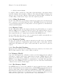
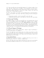
1.1 CPU Model Dependent Features
Microprocessors are generally classified into families with a variety of CPU models or implementations within that family. Within a processor family, there is a high level of binary
compatibility. This family may be based on either an architectural specification or on maintaining compatibility with a popular processor. Recent microprocessor families such as the
SPARC or PowerPC are based on an architectural specification which is independent or any
particular CPU model or implementation. Older families such as the Motorola 68000 and
the Intel x86 evolved as the manufacturer strived to produce higher performance processor
models which maintained binary compatibility with older models.
RTEMS takes advantage of the similarity of the various models within a CPU family.
Although the models do vary in significant ways, the high level of compatibility makes it
possible to share the bulk of the CPU dependent executive code across the entire family.
Each processor family supported by RTEMS has a list of features which vary between
CPU models within a family. For example, the most common model dependent feature
regardless of CPU family is the presence or absence of a floating point unit or coprocessor.
When defining the list of features present on a particular CPU model, one simply notes
that floating point hardware is or is not present and defines a single constant appropriately.
Conditional compilation is utilized to include the appropriate source code for this CPU
model’s feature set. It is important to note that this means that RTEMS is thus compiled
using the appropriate feature set and compilation flags optimal for this CPU model used.
The alternative would be to generate a binary which would execute on all family members
using only the features which were always present.
The
set
of
CPU
model
feature
macros
are
defined
in
the
file
cpukit/score/cpu/CPU/rtems/score/cpu.h based upon the GNU tools multilib
variant that is appropriate for the particular CPU model defined on the compilation
command line.
In each of the architecture specific chapters, this section presents the set of features which
vary across various implementations of the architecture that may be of importance to
RTEMS application developers.
The subsections will vary amongst the target architecture chapters as the specific features
may vary. However, each port will include a few common features such as the CPU Model
4
RTEMS CPU Architecture Supplement
Name and presence of a hardware Floating Point Unit. The common features are described
here.
1.1.1 CPU Model Name
The macro CPU_MODEL_NAME is a string which designates the name of this CPU model. For
example, for the MC68020 processor model from the m68k architecture, this macro is set
to the string "mc68020".
1.1.2 Floating Point Unit
In most architectures, the presence of a floating point unit is an option. It does not matter whether the hardware floating point support is incorporated on-chip or is an external
coprocessor as long as it appears an FPU per the ISA. However, if a hardware FPU is not
present, it is possible that the floating point emulation library for this CPU is not reentrant
and thus context switched by RTEMS.
RTEMS provides two feature macros to indicate the FPU configuration:
• CPU HARDWARE FP is set to TRUE to indicate that a hardware FPU is present.
• CPU SOFTWARE FP is set to TRUE to indicate that a hardware FPU is not
present and that the FP software emulation will be context switched.
1.2 Multilibs
Newlib and GCC provide several target libraries like the libc.a, libm.a and libgcc.a.
These libraries are artifacts of the GCC build process. Newlib is built together with GCC.
To provide optimal support for various chip derivatives and instruction set revisions multiple
variants of these libraries are available for each architecture. For example one set may use
software floating point support and another set may use hardware floating point instructions.
These sets of libraries are called multilibs. Each library set corresponds to an application
binary interface (ABI) and instruction set.
A multilib variant can be usually detected via built-in compiler defines at compile-time.
This mechanism is used by RTEMS to select for example the context switch support for
a particular BSP. The built-in compiler defines corresponding to multilibs are the only
architecture specific defines allowed in the cpukit area of the RTEMS sources.
Invoking the GCC with the -print-multi-lib option lists the available multilibs. Each
line of the output describes one multilib variant. The default variant is denoted by . which is
selected when no or contradicting GCC machine options are selected. The multilib selection
for a target is specified by target makefile fragments (see file t-rtems in the GCC sources
and section The Target Makefile Fragment in the GCC Internals Manual.
1.3 Calling Conventions
Each high-level language compiler generates subroutine entry and exit code based upon a
set of rules known as the compiler’s calling convention. These rules address the following
issues:
• register preservation and usage
• parameter passing
Chapter 1: Port Specific Information
5
• call and return mechanism
A compiler’s calling convention is of importance when interfacing to subroutines written
in another language either assembly or high-level. Even when the high-level language and
target processor are the same, different compilers may use different calling conventions. As
a result, calling conventions are both processor and compiler dependent.
1.3.1 Calling Mechanism
In each of the architecture specific chapters, this subsection will describe the instruction(s)
used to perform a normal subroutine invocation. All RTEMS directives are invoked as
normal C language functions so it is important to the user application to understand the
call and return mechanism.
1.3.2 Register Usage
In each of the architecture specific chapters, this subsection will detail the set of registers
which are NOT preserved across subroutine invocations. The registers which are not preserved are assumed to be available for use as scratch registers. Therefore, the contents of
these registers should not be assumed upon return from any RTEMS directive.
In some architectures, there may be a set of registers made available automatically as a
side-effect of the subroutine invocation mechanism.
1.3.3 Parameter Passing
In each of the architecture specific chapters, this subsection will describe the mechanism
by which the parameters or arguments are passed by the caller to a subroutine. In some
architectures, all parameters are passed on the stack while in others some are passed in
registers.
1.3.4 User-Provided Routines
All user-provided routines invoked by RTEMS, such as user extensions, device drivers, and
MPCI routines, must also adhere to these calling conventions.
1.4 Memory Model
A processor may support any combination of memory models ranging from pure physical
addressing to complex demand paged virtual memory systems. RTEMS supports a flat
memory model which ranges contiguously over the processor’s allowable address space.
RTEMS does not support segmentation or virtual memory of any kind. The appropriate
memory model for RTEMS provided by the targeted processor and related characteristics
of that model are described in this chapter.
1.4.1 Flat Memory Model
Most RTEMS target processors can be initialized to support a flat address space. Although
the size of addresses varies between architectures, on most RTEMS targets, an address is 32bits wide which defines addresses ranging from 0x00000000 to 0xFFFFFFFF (4 gigabytes).
Each address is represented by a 32-bit value and is byte addressable. The address may be
used to reference a single byte, word (2-bytes), or long word (4 bytes). Memory accesses
within this address space may be performed in little or big endian fashion.
6
RTEMS CPU Architecture Supplement
On smaller CPU architectures supported by RTEMS, the address space may only be 20 or
24 bits wide.
If the CPU model has support for virtual memory or segmentation, it is the responsibility
of the Board Support Package (BSP) to initialize the MMU hardware to perform address
translations which correspond to flat memory model.
In each of the architecture specific chapters, this subsection will describe any architecture
characteristics that differ from this general description.
1.5 Interrupt Processing
Different types of processors respond to the occurrence of an interrupt in its own unique
fashion. In addition, each processor type provides a control mechanism to allow for the
proper handling of an interrupt. The processor dependent response to the interrupt modifies
the current execution state and results in a change in the execution stream. Most processors
require that an interrupt handler utilize some special control mechanisms to return to the
normal processing stream. Although RTEMS hides many of the processor dependent details
of interrupt processing, it is important to understand how the RTEMS interrupt manager
is mapped onto the processor’s unique architecture.
RTEMS supports a dedicated interrupt stack for all architectures. On architectures with
hardware support for a dedicated interrupt stack, it will be initialized such that when an
interrupt occurs, the processor automatically switches to this dedicated stack. On architectures without hardware support for a dedicated interrupt stack which is separate from those
of the tasks, RTEMS will support switching to a dedicated stack for interrupt processing.
Without a dedicated interrupt stack, every task in the system MUST have enough stack
space to accommodate the worst case stack usage of that particular task and the interrupt
service routines COMBINED. By supporting a dedicated interrupt stack, RTEMS significantly lowers the stack requirements for each task.
A nested interrupt is processed similarly with the exception that since the CPU is already
executing on the interrupt stack, there is no need to switch to the interrupt stack.
In some configurations, RTEMS allocates the interrupt stack from the Workspace Area. The
amount of memory allocated for the interrupt stack is user configured and based upon the
confdefs.h parameter CONFIGURE_INTERRUPT_STACK_SIZE. This parameter is described
in detail in the Configuring a System chapter of the User’s Guide. On configurations in
which RTEMS allocates the interrupt stack, during the initialization process, RTEMS will
also install its interrupt stack. In other configurations, the interrupt stack is allocated and
installed by the Board Support Package (BSP).
In each of the architecture specific chapters, this section discesses the interrupt response
and control mechanisms of the architecture as they pertain to RTEMS.
1.5.1 Vectoring of an Interrupt Handler
In each of the architecture specific chapters, this subsection will describe the architecture
specific details of the interrupt vectoring process. In particular, it should include a description of the Interrupt Stack Frame (ISF).
Chapter 1: Port Specific Information
7
1.5.2 Interrupt Levels
In each of the architecture specific chapters, this subsection will describe how the interrupt
levels available on this particular architecture are mapped onto the 255 reserved in the task
mode. The interrupt level value of zero (0) should always mean that interrupts are enabled.
Any use of an interrupt level that is is not undefined on a particular architecture may result
in behavior that is unpredictable.
1.5.3 Disabling of Interrupts by RTEMS
During the execution of directive calls, critical sections of code may be executed. When
these sections are encountered, RTEMS disables all external interrupts before the execution
of this section and restores them to the previous level upon completion of the section.
RTEMS has been optimized to ensure that interrupts are disabled for the shortest number
of instructions possible. Since the precise number of instructions and their execution time
varies based upon target CPU family, CPU model, board memory speed, compiler version,
and optimization level, it is not practical to provide the precise number for all possible
RTEMS configurations.
Historically, the measurements were made by hand analyzing and counting the execution
time of instruction sequences during interrupt disable critical sections. For reference purposes, on a 16 Mhz Motorola MC68020, the maximum interrupt disable period was typically
approximately ten (10) to thirteen (13) microseconds. This architecture was memory bound
and had a slow bit scan instruction. In contrast, during the same period a 14 Mhz SPARC
would have a worst case disable time of approximately two (2) to three (3) microseconds
because it had a single cycle bit scan instruction and used fewer cycles for memory accesses.
If you are interested in knowing the worst case execution time for a particular version of
RTEMS, please contact OAR Corporation and we will be happy to product the results as
a consulting service.
Non-maskable interrupts (NMI) cannot be disabled, and ISRs which execute at this level
MUST NEVER issue RTEMS system calls. If a directive is invoked, unpredictable results
may occur due to the inability of RTEMS to protect its critical sections. However, ISRs
that make no system calls may safely execute as non-maskable interrupts.
1.6 Default Fatal Error Processing
Upon detection of a fatal error by either the application or RTEMS during initialization the
rtems_fatal_error_occurred directive supplied by the Fatal Error Manager is invoked.
The Fatal Error Manager will invoke the user-supplied fatal error handlers. If no usersupplied handlers are configured or all of them return without taking action to shutdown
the processor or reset, a default fatal error handler is invoked.
Most of the action performed as part of processing the fatal error are described in detail
in the Fatal Error Manager chapter in the User’s Guide. However, the if no user provided
extension or BSP specific fatal error handler takes action, the final default action is to
invoke a CPU architecture specific function. Typically this function disables interrupts and
halts the processor.
8
RTEMS CPU Architecture Supplement
In each of the architecture specific chapters, this describes the precise operations of the
default CPU specific fatal error handler.
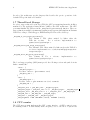
1.7 Thread-Local Storage
In order to support thread-local storage (TLS) the CPU port must implement the facilities
mandated by the application binary interface (ABI) of the CPU architecture. The CPU
port must initialize the TLS area in the _CPU_Context_Initialize() function. There are
support functions available via #include <rtems/score/tls.h> which implement Variants
I and II according to Ulrich Drepper, ELF Handling For Thread-Local Storage.
_TLS_TCB_at_area_begin_initialize()
Uses Variant I, TLS offsets emitted by linker takes the
TCB into account.
For a reference implementation see
cpukit/score/cpu/arm/cpu.c.
_TLS_TCB_before_TLS_block_initialize()
Uses Variant I, TLS offsets emitted by linker neglects the TCB. For
a reference implementation see c/src/lib/libcpu/powerpc/newexceptions/cpu.c.
_TLS_TCB_after_TLS_block_initialize()
Uses Variant II. For a reference
cpukit/score/cpu/sparc/cpu.c.
implementation
see
The board support package (BSP) must provide the following sections and symbols in its
linker command file:
.tdata : {
_TLS_Data_begin = .;
*(.tdata .tdata.* .gnu.linkonce.td.*)
_TLS_Data_end = .;
}
.tbss : {
_TLS_BSS_begin = .;
*(.tbss .tbss.* .gnu.linkonce.tb.*) *(.tcommon)
_TLS_BSS_end = .;
}
_TLS_Data_size = _TLS_Data_end - _TLS_Data_begin;
_TLS_Data_begin = _TLS_Data_size != 0 ? _TLS_Data_begin : _TLS_BSS_begin;
_TLS_Data_end = _TLS_Data_size != 0 ? _TLS_Data_end : _TLS_BSS_begin;
_TLS_BSS_size = _TLS_BSS_end - _TLS_BSS_begin;
_TLS_Size = _TLS_BSS_end - _TLS_Data_begin;
_TLS_Alignment = MAX (ALIGNOF (.tdata), ALIGNOF (.tbss));
1.8 CPU counter
The CPU support must implement the CPU counter interface. A CPU counter is some
free-running counter. It ticks usually with a frequency close to the CPU or system bus
Chapter 1: Port Specific Information
9
clock. On some architectures the actual implementation is board support package dependent. The CPU counter is used for profiling of low-level functions. It is also used to
implement two busy wait functions rtems_counter_delay_ticks() and rtems_counter_
delay_nanoseconds() which may be used in device drivers. It may be also used as an
entropy source for random number generators.
The CPU counter interface uses a CPU port specific unsigned integer type CPU_Counter_
ticks to represent CPU counter values. The CPU port must provide the following two
functions
• _CPU_Counter_read() to read the current CPU counter value, and
• _CPU_Counter_difference() to get the difference between two CPU counter values.
1.9 Interrupt Profiling
The RTEMS profiling needs support by the CPU port for the interrupt entry and exit
times. In case profiling is enabled via the RTEMS build configuration option --enableprofiling (in this case the pre-processor symbol RTEMS_PROFILING is defined) the CPU
port may provide data for the interrupt entry and exit times of the outer-most interrupt.
The CPU port can feed interrupt entry and exit times with the _Profiling_Outer_most_
interrupt_entry_and_exit() function (#include <rtems/score/profiling.h>). For an
example please have a look at cpukit/score/cpu/arm/arm_exc_interrupt.S.
1.10 Board Support Packages
An RTEMS Board Support Package (BSP) must be designed to support a particular processor model and target board combination.
In each of the architecture specific chapters, this section will present a discussion of architecture specific BSP issues. For more information on developing a BSP, refer to BSP and
Device Driver Development Guide and the chapter titled Board Support Packages in the
RTEMS Applications User’s Guide.
1.10.1 System Reset
An RTEMS based application is initiated or re-initiated when the processor is reset or
transfer is passed to it from a boot monitor or ROM monitor.
In each of the architecture specific chapters, this subsection describes the actions that the
BSP must tak assuming the application gets control when the microprocessor is reset.
Chapter 2: ARM Specific Information
11
2 ARM Specific Information
This chapter discusses the ARM architecture dependencies in this port of RTEMS. The
ARM family has a wide variety of implementations by a wide range of vendors. Consequently, there are many, many CPU models within it. Currently the ARMv5 (and compatible) architecture version as defined in the ARMv5 Architecture Reference Manual is
supported by RTEMS.
Architecture Documents
For information on the ARM architecture refer to the ARM Infocenter.
2.1 CPU Model Dependent Features
This section presents the set of features which vary across ARM implementations and are
of importance to RTEMS. The set of CPU model feature macros are defined in the file
cpukit/score/cpu/arm/rtems/score/arm.h based upon the particular CPU model flags
specified on the compilation command line.
2.1.1 CPU Model Name
The macro CPU_MODEL_NAME is a string which designates the architectural level of this CPU
model. See in cpukit/score/cpu/arm/rtems/score/arm.h for the values.
2.1.2 Count Leading Zeroes Instruction
The ARMv5 and later has the count leading zeroes clz instruction which could be used to
speed up the find first bit operation. The use of this instruction should significantly speed
up the scheduling associated with a thread blocking. This is currently not used.
2.1.3 Floating Point Unit
The following floating point units are supported.
• VFPv3-D32/NEON (for example available on Cortex-A processors)
• VFPv3-D16 (for example available on Cortex-R processors)
• FPv4-SP-D16 (for example available on Cortex-M processors)
2.2 Multilibs
The following multilibs are available:
1. .: ARMv4T, ARM instruction set
2. thumb: ARMv4T, Thumb-1 instruction set
3. thumb/armv6-m: ARMv6M, subset of Thumb-2 instruction set
4. thumb/armv7-a: ARMv7-A, Thumb-2 instruction set
5. thumb/armv7-a/neon/hard: ARMv7-A, Thumb-2 instruction set with hard-float
ABI Neon and VFP-D32 support
6. thumb/armv7-r: ARMv7-R, Thumb-2 instruction set
12
RTEMS CPU Architecture Supplement
7. thumb/armv7-r/vfpv3-d16/hard: ARMv7-R, Thumb-2 instruction set with hardfloat ABI VFP-D16 support
8. thumb/armv7-m: ARMv7-M, Thumb-2 instruction set with hardware integer division
(SDIV/UDIV)
9. thumb/armv7-m/fpv4-sp-d16: ARMv7-M, Thumb-2 instruction set with hardware
integer division (SDIV/UDIV) and hard-float ABI FPv4-SP support
10. eb/thumb/armv7-r: ARMv7-R, Big-endian Thumb-2 instruction set
11. eb/thumb/armv7-r/vfpv3-d16/hard: ARMv7-R, Big-endian Thumb-2 instruction
set with hard-float ABI VFP-D16 support
Multilib 1. and 2. support the standard ARM7TDMI and ARM926EJ-S targets.
Multilib 3. supports the Cortex-M0 and Cortex-M1 cores.
Multilib 8. supports the Cortex-M3 and Cortex-M4 cores, which have a special hardware
integer division instruction (this is not present in the A and R profiles).
Multilib 9. supports the Cortex-M4 cores with a floating point unit.
Multilib 4. and 5. support the Cortex-A processors.
Multilib 6., 7., 10. and 11. support the Cortex-R processors. Here also big-endian variants
are available.
Use for example the following GCC options
-mthumb -march=armv7-a -mfpu=neon -mfloat-abi=hard -mtune=cortex-a9
to build an application or BSP for the ARMv7-A architecture and tune the code for a
Cortex-A9 processor. It is important to select the options used for the multilibs. For
example
-mthumb -mcpu=cortex-a9
alone will not select the ARMv7-A multilib.
2.3 Calling Conventions
Please refer to the Procedure Call Standard for the ARM Architecture.
2.4 Memory Model
A flat 32-bit memory model is supported. The board support package must take care about
the MMU if necessary.
2.5 Interrupt Processing
The ARMv5 (and compatible) architecture has seven exception types:
•
•
•
•
Reset
Undefined
Software Interrupt (SWI)
Prefetch Abort
Chapter 2: ARM Specific Information
13
• Data Abort
• Interrupt (IRQ)
• Fast Interrupt (FIQ)
Of these types only the IRQ has explicit operating system support. It is intentional that
the FIQ is not supported by the operating system. Without operating system support for
the FIQ it is not necessary to disable them during critical sections of the system.
2.5.1 Interrupt Levels
The RTEMS interrupt level mapping scheme for the ARM is not a numeric level as on
most RTEMS ports. It is a bit mapping that corresponds the enable bit postions in the
Current Program Status Register (CPSR). There are only two levels: IRQ enabled and IRQ
disabled.
2.5.2 Interrupt Stack
The board support package must initialize the interrupt stack. The memory for the stacks
is usually reserved in the linker script.
2.6 Default Fatal Error Processing
The default fatal error handler for this architecture performs the following actions:
• disables operating system supported interrupts (IRQ),
• places the error code in r0, and
• executes an infinite loop to simulate a halt processor instruction.
2.7 Thread-Local Storage
Thread-local storage is supported.
Chapter 3: Atmel AVR Specific Information
15
3 Atmel AVR Specific Information
This chapter discusses the AVR architecture dependencies in this port of RTEMS.
Architecture Documents
For information on the AVR architecture, refer to the following documents available from
Atmel.
TBD
• See other CPUs for documentation reference formatting examples.
3.1 CPU Model Dependent Features
CPUs of the AVR 53X only differ in the peripherals and thus in the device drivers. This
port does not yet support the 56X dual core variants.
3.1.1 Count Leading Zeroes Instruction
The AVR CPU has the XXX instruction which could be used to speed up the find first
bit operation. The use of this instruction should significantly speed up the scheduling
associated with a thread blocking.
3.2 Calling Conventions
3.2.1 Processor Background
The AVR architecture supports a simple call and return mechanism. A subroutine is invoked
via the call (call) instruction. This instruction saves the return address in the RETS register
and transfers the execution to the given address.
It is the called funcions responsability to use the link instruction to reserve space on the
stack for the local variables. Returning from a subroutine is done by using the RTS (RTS)
instruction which loads the PC with the adress stored in RETS.
It is is important to note that the call instruction does not automatically save or restore
any registers. It is the responsibility of the high-level language compiler to define the register
preservation and usage convention.
3.2.2 Register Usage
A called function may clobber all registers, except RETS, R4-R7, P3-P5, FP and SP. It
may also modify the first 12 bytes in the callers stack frame which is used as an argument
area for the first three arguments (which are passed in R0...R3 but may be placed on the
stack by the called function).
3.2.3 Parameter Passing
RTEMS assumes that the AVR GCC calling convention is followed. The first three parameters are stored in registers R0, R1, and R2. All other parameters are put pushed on the
stack. The result is returned through register R0.
16
RTEMS CPU Architecture Supplement
3.3 Memory Model
The AVR family architecutre support a single unified 4 GB byte address space using 32-bit
addresses. It maps all resources like internal and external memory and IO registers into
separate sections of this common address space.
The AVR architcture supports some form of memory protection via its Memory Management Unit. Since the AVR port runs in supervisior mode this memory protection mechanisms are not used.
3.4 Interrupt Processing
Discussed in this chapter are the AVR’s interrupt response and control mechanisms as they
pertain to RTEMS.
3.4.1 Vectoring of an Interrupt Handler
TBD
3.4.2 Disabling of Interrupts by RTEMS
During interrupt disable critical sections, RTEMS disables interrupts to level N (N) before
the execution of this section and restores them to the previous level upon completion of
the section. RTEMS uses the instructions CLI and STI to enable and disable Interrupts.
Emulation, Reset, NMI and Exception Interrupts are never disabled.
3.4.3 Interrupt Stack
The AVR Architecture works with two different kind of stacks, User and Supervisor Stack.
Since RTEMS and its Application run in supervisor mode, all interrupts will use the interrupted tasks stack for execution.
3.5 Default Fatal Error Processing
The default fatal error handler for the AVR performs the following actions:
• disables processor interrupts,
• places the error code in r0, and
• executes an infinite loop (while(0); to simulate a halt processor instruction.
3.6 Thread-Local Storage
Thread-local storage is not supported due to a broken tool chain.
3.7 Board Support Packages
3.7.1 System Reset
TBD
Chapter 4: Blackfin Specific Information
17
4 Blackfin Specific Information
This chapter discusses the Blackfin architecture dependencies in this port of RTEMS.
Architecture Documents
For information on the Blackfin architecture, refer to the following documents available
from Analog Devices.
TBD
• "ADSP-BF533
Blackfin
Processor
Hardware
Reference."
http://www.analog.com/UploadedFiles/Associated_Docs/892485982bf533_
hwr.pdf
4.1 CPU Model Dependent Features
CPUs of the Blackfin 53X only differ in the peripherals and thus in the device drivers. This
port does not yet support the 56X dual core variants.
4.1.1 Count Leading Zeroes Instruction
The Blackfin CPU has the BITTST instruction which could be used to speed up the find
first bit operation. The use of this instruction should significantly speed up the scheduling
associated with a thread blocking.
4.2 Calling Conventions
This section is heavily based on content taken from the Blackfin uCLinux documentation wiki which is edited by Analog Devices and Arcturus Networks.
http://docs.blackfin.uclinux.org/
4.2.1 Processor Background
The Blackfin architecture supports a simple call and return mechanism. A subroutine is
invoked via the call (call) instruction. This instruction saves the return address in the
RETS register and transfers the execution to the given address.
It is the called funcions responsability to use the link instruction to reserve space on the
stack for the local variables. Returning from a subroutine is done by using the RTS (RTS)
instruction which loads the PC with the adress stored in RETS.
It is is important to note that the call instruction does not automatically save or restore
any registers. It is the responsibility of the high-level language compiler to define the register
preservation and usage convention.
4.2.2 Register Usage
A called function may clobber all registers, except RETS, R4-R7, P3-P5, FP and SP. It
may also modify the first 12 bytes in the callers stack frame which is used as an argument
area for the first three arguments (which are passed in R0...R3 but may be placed on the
stack by the called function).
18
RTEMS CPU Architecture Supplement
4.2.3 Parameter Passing
RTEMS assumes that the Blackfin GCC calling convention is followed. The first three
parameters are stored in registers R0, R1, and R2. All other parameters are put pushed on
the stack. The result is returned through register R0.
4.3 Memory Model
The Blackfin family architecutre support a single unified 4 GB byte address space using
32-bit addresses. It maps all resources like internal and external memory and IO registers
into separate sections of this common address space.
The Blackfin architcture supports some form of memory protection via its Memory Management Unit. Since the Blackfin port runs in supervisior mode this memory protection
mechanisms are not used.
4.4 Interrupt Processing
Discussed in this chapter are the Blackfin’s interrupt response and control mechanisms as
they pertain to RTEMS. The Blackfin architecture support 16 kinds of interrupts broken
down into Core and general-purpose interrupts.
4.4.1 Vectoring of an Interrupt Handler
RTEMS maps levels 0 -15 directly to Blackfins event vectors EVT0 - EVT15. Since EVT0 EVT6 are core events and it is suggested to use EVT15 and EVT15 for Software interrupts,
7 Interrupts (EVT7-EVT13) are left for periferical use.
When installing an RTEMS interrupt handler RTEMS installs a generic Interrupt Handler
which saves some context and enables nested interrupt servicing and then vectors to the
users interrupt handler.
4.4.2 Disabling of Interrupts by RTEMS
During interrupt disable critical sections, RTEMS disables interrupts to level four (4) before
the execution of this section and restores them to the previous level upon completion of
the section. RTEMS uses the instructions CLI and STI to enable and disable Interrupts.
Emulation, Reset, NMI and Exception Interrupts are never disabled.
4.4.3 Interrupt Stack
The Blackfin Architecture works with two different kind of stacks, User and Supervisor
Stack. Since RTEMS and its Application run in supervisor mode, all interrupts will use the
interrupted tasks stack for execution.
4.5 Default Fatal Error Processing
The default fatal error handler for the Blackfin performs the following actions:
• disables processor interrupts,
• places the error code in r0, and
• executes an infinite loop (while(0); to simulate a halt processor instruction.
Chapter 4: Blackfin Specific Information
4.6 Thread-Local Storage
Thread-local storage is not implemented.
4.7 Board Support Packages
4.7.1 System Reset
TBD
19
Chapter 5: Renesas H8/300 Specific Information
5 Renesas H8/300 Specific Information
5.1 Thread-Local Storage
Thread-local storage is not implemented.
21
Chapter 6: Intel/AMD x86 Specific Information
23
6 Intel/AMD x86 Specific Information
This chapter discusses the Intel x86 architecture dependencies in this port of RTEMS. This
family has multiple implementations from multiple vendors and suffers more from having
evolved rather than being designed for growth.
For information on the i386 processor, refer to the following documents:
• 386 Programmer’s Reference Manual, Intel, Order No. 230985-002.
• 386 Microprocessor Hardware Reference Manual, Intel, Order No. 231732-003.
• 80386 System Software Writer’s Guide, Intel, Order No. 231499-001.
• 80387 Programmer’s Reference Manual, Intel, Order No. 231917-001.
6.1 CPU Model Dependent Features
This section presents the set of features which vary across i386 implementations and are
of importance to RTEMS. The set of CPU model feature macros are defined in the file
cpukit/score/cpu/i386/i386.h based upon the particular CPU model specified on the
compilation command line.
6.1.1 bswap Instruction
The macro I386_HAS_BSWAP is set to 1 to indicate that this CPU model has the bswap
instruction which endian swaps a thirty-two bit quantity. This instruction appears to be
present in all CPU models i486’s and above.
6.2 Calling Conventions
6.2.1 Processor Background
The i386 architecture supports a simple yet effective call and return mechanism. A subroutine is invoked via the call (call) instruction. This instruction pushes the return address
on the stack. The return from subroutine (ret) instruction pops the return address off the
current stack and transfers control to that instruction. It is is important to note that the
i386 call and return mechanism does not automatically save or restore any registers. It is
the responsibility of the high-level language compiler to define the register preservation and
usage convention.
6.2.2 Calling Mechanism
All RTEMS directives are invoked using a call instruction and return to the user application
via the ret instruction.
6.2.3 Register Usage
As discussed above, the call instruction does not automatically save any registers. RTEMS
uses the registers EAX, ECX, and EDX as scratch registers. These registers are not preserved by RTEMS directives therefore, the contents of these registers should not be assumed
upon return from any RTEMS directive.
24
RTEMS CPU Architecture Supplement
6.2.4 Parameter Passing
RTEMS assumes that arguments are placed on the current stack before the directive is
invoked via the call instruction. The first argument is assumed to be closest to the return
address on the stack. This means that the first argument of the C calling sequence is pushed
last. The following pseudo-code illustrates the typical sequence used to call a RTEMS
directive with three (3) arguments:
push third argument
push second argument
push first argument
invoke directive
remove arguments from the stack
The arguments to RTEMS are typically pushed onto the stack using a push instruction.
These arguments must be removed from the stack after control is returned to the caller.
This removal is typically accomplished by adding the size of the argument list in bytes to
the stack pointer.
6.3 Memory Model
6.3.1 Flat Memory Model
RTEMS supports the i386 protected mode, flat memory model with paging disabled. In this
mode, the i386 automatically converts every address from a logical to a physical address
each time it is used. The i386 uses information provided in the segment registers and the
Global Descriptor Table to convert these addresses. RTEMS assumes the existence of the
following segments:
• a single code segment at protection level (0) which contains all application and
executive code.
• a single data segment at protection level zero (0) which contains all application and
executive data.
The i386 segment registers and associated selectors must be initialized when the initialize executive directive is invoked. RTEMS treats the segment registers as system registers
and does not modify or context switch them.
This i386 memory model supports a flat 32-bit address space with addresses ranging from
0x00000000 to 0xFFFFFFFF (4 gigabytes). Each address is represented by a 32-bit value
and is byte addressable. The address may be used to reference a single byte, half-word
(2-bytes), or word (4 bytes).
6.4 Interrupt Processing
Although RTEMS hides many of the processor dependent details of interrupt processing,
it is important to understand how the RTEMS interrupt manager is mapped onto the
processor’s unique architecture. Discussed in this chapter are the the processor’s response
and control mechanisms as they pertain to RTEMS.
Chapter 6: Intel/AMD x86 Specific Information
25
6.4.1 Vectoring of Interrupt Handler
Although the i386 supports multiple privilege levels, RTEMS and all user software executes
at privilege level 0. This decision was made by the RTEMS designers to enhance compatibility with processors which do not provide sophisticated protection facilities like those of
the i386. This decision greatly simplifies the discussion of i386 processing, as one need only
consider interrupts without privilege transitions.
Upon receipt of an interrupt the i386 automatically performs the following actions:
• pushes the EFLAGS register
• pushes the far address of the interrupted instruction
• vectors to the interrupt service routine (ISR).
A nested interrupt is processed similarly by the i386.
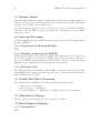
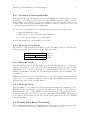
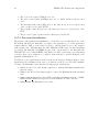
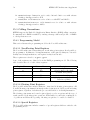
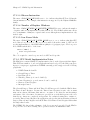
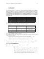
6.4.2 Interrupt Stack Frame
The structure of the Interrupt Stack Frame for the i386 which is placed on the interrupt
stack by the processor in response to an interrupt is as follows:
Old EFLAGS Register
UNUSED
Old CS
Old
EIP
ESP+8
ESP+4
ESP
6.4.3 Interrupt Levels
Although RTEMS supports 256 interrupt levels, the i386 only supports two – enabled and
disabled. Interrupts are enabled when the interrupt-enable flag (IF) in the extended flags
(EFLAGS) is set. Conversely, interrupt processing is inhibited when the IF is cleared.
During a non-maskable interrupt, all other interrupts, including other non-maskable ones,
are inhibited.
RTEMS interrupt levels 0 and 1 such that level zero (0) indicates that interrupts are fully
enabled and level one that interrupts are disabled. All other RTEMS interrupt levels are
undefined and their behavior is unpredictable.
6.4.4 Interrupt Stack
The i386 family does not support a dedicated hardware interrupt stack. On this processor,
RTEMS allocates and manages a dedicated interrupt stack. As part of vectoring a nonnested interrupt service routine, RTEMS switches from the stack of the interrupted task to
a dedicated interrupt stack. When a non-nested interrupt returns, RTEMS switches back
to the stack of the interrupted stack. The current stack pointer is not altered by RTEMS
on nested interrupt.
6.5 Default Fatal Error Processing
The default fatal error handler for this architecture disables processor interrupts, places the
error code in EAX, and executes a HLT instruction to halt the processor.
26
RTEMS CPU Architecture Supplement
6.6 Thread-Local Storage
Thread-local storage is not implemented.
6.7 Board Support Packages
6.7.1 System Reset
An RTEMS based application is initiated when the i386 processor is reset. When the i386
is reset,
• The EAX register is set to indicate the results of the processor’s power-up self test.
If the self-test was not executed, the contents of this register are undefined. Otherwise, a non-zero value indicates the processor is faulty and a zero value indicates a
successful self-test.
• The DX register holds a component identifier and revision level. DH contains 3 to
indicate an i386 component and DL contains a unique revision level indicator.
• Control register zero (CR0) is set such that the processor is in real mode with
paging disabled. Other portions of CR0 are used to indicate the presence of a
numeric coprocessor.
• All bits in the extended flags register (EFLAG) which are not permanently set are
cleared. This inhibits all maskable interrupts.
• The Interrupt Descriptor Register (IDTR) is set to point at address zero.
• All segment registers are set to zero.
• The instruction pointer is set to 0x0000FFF0. The first instruction executed after a
reset is actually at 0xFFFFFFF0 because the i386 asserts the upper twelve address
until the first intersegment (FAR) JMP or CALL instruction. When a JMP or
CALL is executed, the upper twelve address lines are lowered and the processor
begins executing in the first megabyte of memory.
Typically, an intersegment JMP to the application’s initialization code is placed at address
0xFFFFFFF0.
6.7.2 Processor Initialization
This initialization code is responsible for initializing all data structures required by the i386
in protected mode and for actually entering protected mode. The i386 must be placed in
protected mode and the segment registers and associated selectors must be initialized before
the initialize executive directive is invoked.
The initialization code is responsible for initializing the Global Descriptor Table such that
the i386 is in the thirty-two bit flat memory model with paging disabled. In this mode, the
i386 automatically converts every address from a logical to a physical address each time it
is used. For more information on the memory model used by RTEMS, please refer to the
Memory Model chapter in this document.
Since the processor is in real mode upon reset, the processor must be switched to protected
mode before RTEMS can execute. Before switching to protected mode, at least one descriptor table and two descriptors must be created. Descriptors are needed for a code segment
and a data segment. ( This will give you the flat memory model.) The stack can be placed
Chapter 6: Intel/AMD x86 Specific Information
27
in a normal read/write data segment, so no descriptor for the stack is needed. Before the
GDT can be used, the base address and limit must be loaded into the GDTR register using
an LGDT instruction.
If the hardware allows an NMI to be generated, you need to create the IDT and a gate for
the NMI interrupt handler. Before the IDT can be used, the base address and limit for the
idt must be loaded into the IDTR register using an LIDT instruction.
Protected mode is entered by setting thye PE bit in the CR0 register. Either a LMSW
or MOV CR0 instruction may be used to set this bit. Because the processor overlaps the
interpretation of several instructions, it is necessary to discard the instructions from the
read-ahead cache. A JMP instruction immediately after the LMSW changes the flow and
empties the processor if intructions which have been pre-fetched and/or decoded. At this
point, the processor is in protected mode and begins to perform protected mode application
initialization.
If the application requires that the IDTR be some value besides zero, then it should set it
to the required value at this point. All tasks share the same i386 IDTR value. Because
interrupts are enabled automatically by RTEMS as part of the initialize executive directive,
the IDTR MUST be set properly before this directive is invoked to insure correct interrupt
vectoring. If processor caching is to be utilized, then it should be enabled during the
reset application initialization code. The reset code which is executed before the call to
initialize executive has the following requirements:
For more information regarding the i386 data structures and their contents, refer to Intel’s
386 Programmer’s Reference Manual.
Chapter 7: Lattice Mico32 Specific Information
29
7 Lattice Mico32 Specific Information
This chaper discusses the Lattice Mico32 architecture dependencies in this port of RTEMS.
The Lattice Mico32 is a 32-bit Harvard, RISC architecture "soft" microprocessor, available
for free with an open IP core licensing agreement. Although mainly targeted for Lattice
FPGA devices the microprocessor can be implemented on other vendors’ FPGAs, too.
Architecture Documents
For information on the Lattice Mico32 architecture, refer to the following documents available from Lattice Semiconductor http://www.latticesemi.com/.
• "LatticeMico32
Processor
Reference
Manual"
http://www.latticesemi.com/dynamic/view_document.cfm?document_
id=20890
7.1 CPU Model Dependent Features
The Lattice Mico32 architecture allows for different configurations of the processor. This
port is based on the assumption that the following options are implemented:
•
•
•
•
•
•
•
hardware multiplier
hardware divider
hardware barrel shifter
sign extension instructions
instruction cache
data cache
debug
7.2 Register Architecture
This section gives a brief introduction to the register architecture of the Lattice Mico32
processor.
The Lattice Mico32 is a RISC archictecture processor with a 32-register file of 32-bit registers.
Register Name
r0
r1-r25
r26/gp
r27/fp
r28/sp
r29/ra
r30/ea
r31/ba
Function
holds value zero
general purpose
general pupose / global pointer
general pupose / frame pointer
stack pointer
return address
exception address
breakpoint address
Note that on processor startup all register values are undefined including r0, thus r0 has to
be initialized to zero.
30
RTEMS CPU Architecture Supplement
7.3 Calling Conventions
7.3.1 Calling Mechanism
A call instruction places the return address to register r29 and a return from subroutine
(ret) is actually a branch to r29/ra.
7.3.2 Register Usage
A subroutine may freely use registers r1 to r10 which are not preserved across subroutine
invocations.
7.3.3 Parameter Passing
When calling a C function the first eight arguments are stored in registers r1 to r8. Registers
r1 and r2 hold the return value.
7.4 Memory Model
The Lattice Mico32 processor supports a flat memory model with a 4 Gbyte address space
with 32-bit addresses.
The following data types are supported:
Type
unsigned byte
signed byte
unsigned half-word
signed half-word
unsigned word
signed word
Bits
8
8
16
16
32
32
C Compiler Type
unsigned char
char
unsigned short
short
unsigned int / unsigned long
int / long
Data accesses need to be aligned, with unaligned accesses result are undefined.
7.5 Interrupt Processing
The Lattice Mico32 has 32 interrupt lines which are however served by only one exception
vector. When an interrupt occurs following happens:
• address of next instruction placed in r30/ea
• IE field of IE CSR saved to EIE field and IE field cleared preventing further exceptions from occuring.
• branch to interrupt exception address EBA CSR + 0xC0
The interrupt exception handler determines from the state of the interrupt pending registers
(IP CSR) and interrupt enable register (IE CSR) which interrupt to serve and jumps to the
interrupt routine pointed to by the corresponding interrupt vector.
For now there is no dedicated interrupt stack so every task in the system MUST have
enough stack space to accommodate the worst case stack usage of that particular task and
the interrupt service routines COMBINED.
Nested interrupts are not supported.
Chapter 7: Lattice Mico32 Specific Information
31
7.6 Default Fatal Error Processing
Upon detection of a fatal error by either the application or RTEMS during initialization the
rtems_fatal_error_occurred directive supplied by the Fatal Error Manager is invoked.
The Fatal Error Manager will invoke the user-supplied fatal error handlers. If no usersupplied handlers are configured or all of them return without taking action to shutdown
the processor or reset, a default fatal error handler is invoked.
Most of the action performed as part of processing the fatal error are described in detail
in the Fatal Error Manager chapter in the User’s Guide. However, the if no user provided
extension or BSP specific fatal error handler takes action, the final default action is to
invoke a CPU architecture specific function. Typically this function disables interrupts and
halts the processor.
In each of the architecture specific chapters, this describes the precise operations of the
default CPU specific fatal error handler.
7.7 Thread-Local Storage
Thread-local storage is not implemented.
7.8 Board Support Packages
An RTEMS Board Support Package (BSP) must be designed to support a particular processor model and target board combination.
In each of the architecture specific chapters, this section will present a discussion of architecture specific BSP issues. For more information on developing a BSP, refer to BSP and
Device Driver Development Guide and the chapter titled Board Support Packages in the
RTEMS Applications User’s Guide.
7.8.1 System Reset
An RTEMS based application is initiated or re-initiated when the processor is reset.
Chapter 8: Renesas M32C Specific Information
8 Renesas M32C Specific Information
8.1 Thread-Local Storage
Thread-local storage is not implemented.
33
Chapter 9: Renesas M32R Specific Information
9 Renesas M32R Specific Information
9.1 Thread-Local Storage
Thread-local storage is not implemented.
35
Chapter 10: M68xxx and Coldfire Specific Information
37
10 M68xxx and Coldfire Specific Information
This chapter discusses the Freescale (formerly Motorola) MC68xxx and Coldfire architectural dependencies. The MC68xxx family has a wide variety of CPU models within it based
upon different CPU core implementations. Ignoring the Coldfire parts, the part numbers
for these models are generally divided into MC680xx and MC683xx. The MC680xx models
are more general purpose processors with no integrated peripherals. The MC683xx models,
on the other hand, are more specialized and have a variety of peripherals on chip including
sophisticated timers and serial communications controllers.
Architecture Documents
For information on the MC68xxx and Coldfire architecture, refer to the following documents
available from Freescale website (http//www.freescale.com/):
• M68000 Family Reference, Motorola, FR68K/D.
• MC68020 User’s Manual, Motorola, MC68020UM/AD.
• MC68881/MC68882 Floating-Point Coprocessor User’s
MC68881UM/AD.
Manual,
Motorola,
10.1 CPU Model Dependent Features
This section presents the set of features which vary across m68k/Coldfire implementations
that are of importance to RTEMS. The set of CPU model feature macros are defined in
the file cpukit/score/cpu/m68k/m68k.h based upon the particular CPU model selected
on the compilation command line.
10.1.1 BFFFO Instruction
The macro M68K_HAS_BFFFO is set to 1 to indicate that this CPU model has the bfffo
instruction.
10.1.2 Vector Base Register
The macro M68K_HAS_VBR is set to 1 to indicate that this CPU model has a vector base
register (vbr).
10.1.3 Separate Stacks
The macro M68K_HAS_SEPARATE_STACKS is set to 1 to indicate that this CPU model has
separate interrupt, user, and supervisor mode stacks.
10.1.4 Pre-Indexing Address Mode
The macro M68K_HAS_PREINDEXING is set to 1 to indicate that this CPU model has the
pre-indexing address mode.
10.1.5 Extend Byte to Long Instruction
The macro M68K_HAS_EXTB_L is set to 1 to indicate that this CPU model has the extb.l
instruction. This instruction is supposed to be available in all models based on the cpu32
core as well as mc68020 and up models.
38
RTEMS CPU Architecture Supplement
10.2 Calling Conventions
The MC68xxx architecture supports a simple yet effective call and return mechanism. A
subroutine is invoked via the branch to subroutine (bsr) or the jump to subroutine (jsr)
instructions. These instructions push the return address on the current stack. The return
from subroutine (rts) instruction pops the return address off the current stack and transfers
control to that instruction. It is is important to note that the MC68xxx call and return
mechanism does not automatically save or restore any registers. It is the responsibility of
the high-level language compiler to define the register preservation and usage convention.
10.2.1 Calling Mechanism
All RTEMS directives are invoked using either a bsr or jsr instruction and return to the
user application via the rts instruction.
10.2.2 Register Usage
As discussed above, the bsr and jsr instructions do not automatically save any registers.
RTEMS uses the registers D0, D1, A0, and A1 as scratch registers. These registers are
not preserved by RTEMS directives therefore, the contents of these registers should not be
assumed upon return from any RTEMS directive.
10.2.3 Parameter Passing
RTEMS assumes that arguments are placed on the current stack before the directive is
invoked via the bsr or jsr instruction. The first argument is assumed to be closest to the
return address on the stack. This means that the first argument of the C calling sequence
is pushed last. The following pseudo-code illustrates the typical sequence used to call a
RTEMS directive with three (3) arguments:
push third argument
push second argument
push first argument
invoke directive
remove arguments from the stack
The arguments to RTEMS are typically pushed onto the stack using a move instruction with
a pre-decremented stack pointer as the destination. These arguments must be removed from
the stack after control is returned to the caller. This removal is typically accomplished by
adding the size of the argument list in bytes to the current stack pointer.
10.3 Memory Model
The MC68xxx family supports a flat 32-bit address space with addresses ranging from
0x00000000 to 0xFFFFFFFF (4 gigabytes). Each address is represented by a 32-bit value
and is byte addressable. The address may be used to reference a single byte, word (2-bytes),
or long word (4 bytes). Memory accesses within this address space are performed in big
endian fashion by the processors in this family.
Some of the MC68xxx family members such as the MC68020, MC68030, and MC68040
support virtual memory and segmentation. The MC68020 requires external hardware support such as the MC68851 Paged Memory Management Unit coprocessor which is typically
Chapter 10: M68xxx and Coldfire Specific Information
39
used to perform address translations for these systems. RTEMS does not support virtual
memory or segmentation on any of the MC68xxx family members.
10.4 Interrupt Processing
Discussed in this section are the MC68xxx’s interrupt response and control mechanisms as
they pertain to RTEMS.
10.4.1 Vectoring of an Interrupt Handler
Depending on whether or not the particular CPU supports a separate interrupt stack, the
MC68xxx family has two different interrupt handling models.
10.4.1.1 Models Without Separate Interrupt Stacks
Upon receipt of an interrupt the MC68xxx family members without separate interrupt
stacks automatically perform the following actions:
• To Be Written
10.4.1.2 Models With Separate Interrupt Stacks
Upon receipt of an interrupt the MC68xxx family members with separate interrupt stacks
automatically perform the following actions:
• saves the current status register (SR),
• clears the master/interrupt (M) bit of the SR to indicate the switch from master
state to interrupt state,
• sets the privilege mode to supervisor,
• suppresses tracing,
• sets the interrupt mask level equal to the level of the interrupt being serviced,
• pushes an interrupt stack frame (ISF), which includes the program counter (PC),
the status register (SR), and the format/exception vector offset (FVO) word, onto
the supervisor and interrupt stacks,
• switches the current stack to the interrupt stack and vectors to an interrupt service
routine (ISR). If the ISR was installed with the interrupt catch directive, then the
RTEMS interrupt handler will begin execution. The RTEMS interrupt handler saves
all registers which are not preserved according to the calling conventions and invokes
the application’s ISR.
A nested interrupt is processed similarly by these CPU models with the exception that only
a single ISF is placed on the interrupt stack and the current stack need not be switched.
The FVO word in the Interrupt Stack Frame is examined by RTEMS to determine when
an outer most interrupt is being exited. Since the FVO is used by RTEMS for this purpose,
the user application code MUST NOT modify this field.
The following shows the Interrupt Stack Frame for MC68xxx CPU models with separate
interrupt stacks:
40
RTEMS CPU Architecture Supplement
Status Register
Program Counter High
Program Counter Low
Format/Vector Offset
0x0
0x2
0x4
0x6
10.4.2 CPU Models Without VBR and RAM at 0
This is from a post by Zoltan Kocsi <[email protected]> and is a nice trick in certain
situations. In his words:
I think somebody on this list asked about the interupt vector handling w/o VBR and RAM
at 0. The usual trick is to initialise the vector table (except the first 2 two entries, of course)
to point to the same location BUT you also add the vector number times 0x1000000 to them.
That is, bits 31-24 contain the vector number and 23-0 the address of the common handler.
Since the PC is 32 bit wide but the actual address bus is only 24, the top byte will be in
the PC but will be ignored when jumping onto your routine.
Then your common interrupt routine gets this info by loading the PC into some register
and based on that info, you can jump to a vector in a vector table pointed by a virtual
VBR:
//
//
//
Real vector table at 0
.long
.long
.long
.long
.long
...
.long
//
//
//
//
//
//
//
initial_sp
initial_pc
myhandler+0x02000000
myhandler+0x03000000
myhandler+0x04000000
myhandler+0xff000000
This handler will jump to the interrupt routine
of which
the address is stored at VBR[ vector_no ]
The registers and stackframe will be intact, the interrupt
routine will see exactly what it would see if it was called
directly from the HW vector table at 0.
.comm
myhandler:
move.l
move.l
lea
move.l
swap
VBR,4,2
%d0,-(%sp)
%a0,-(%sp)
0(%pc),%a0
%a0,%d0
%d0
// This defines the ’virtual’ VBR
// From C: extern void *VBR;
//
//
//
//
//
//
At entry, PC contains the full vector
Save d0
Save a0
Get the value of the PC
Copy it to a data reg, d0 is VV??????
Now d0 is ????VV??
Chapter 10: M68xxx and Coldfire Specific Information
and.w
lsr.w
move.l
move.l
move.l
move.l
move.l
ret
#0xff00,%d0
#6,%d0
VBR,%a0
(%a0,%d0.w),%a0
4(%sp),%d0
%a0,4(%sp)
(%sp)+,%a0
//
//
//
//
//
//
//
//
//
41
Now d0 is ????VV00 (1)
Now d0.w contains the VBR table offset
Get the address from VBR to a0
Fetch the vector
Restore d0
Place target address to the stack
Restore a0, target address is on TOS
This will jump to the handler and
restore the stack
(1) If ’myhandler’ is guaranteed to be in the first 64K, e.g. just
after the vector table then that insn is not needed.
There are probably shorter ways to do this, but it I believe is enough to illustrate the trick.
Optimisation is left as an exercise to the reader :-)
10.4.3 Interrupt Levels
Eight levels (0-7) of interrupt priorities are supported by MC68xxx family members with
level seven (7) being the highest priority. Level zero (0) indicates that interrupts are fully
enabled. Interrupt requests for interrupts with priorities less than or equal to the current
interrupt mask level are ignored.
Although RTEMS supports 256 interrupt levels, the MC68xxx family only supports eight.
RTEMS interrupt levels 0 through 7 directly correspond to MC68xxx interrupt levels. All
other RTEMS interrupt levels are undefined and their behavior is unpredictable.
10.5 Default Fatal Error Processing
The default fatal error handler for this architecture disables processor interrupts to level 7,
places the error code in D0, and executes a stop instruction to simulate a halt processor
instruction.
10.6 Thread-Local Storage
Thread-local storage is supported.
10.7 Board Support Packages
10.7.1 System Reset
An RTEMS based application is initiated or re-initiated when the MC68020 processor is
reset. When the MC68020 is reset, the processor performs the following actions:
• The tracing bits of the status register are cleared to disable tracing.
• The supervisor interrupt state is entered by setting the supervisor (S) bit and clearing the master/interrupt (M) bit of the status register.
• The interrupt mask of the status register is set to level 7 to effectively disable all
maskable interrupts.
42
RTEMS CPU Architecture Supplement
• The vector base register (VBR) is set to zero.
• The cache control register (CACR) is set to zero to disable and freeze the processor
cache.
• The interrupt stack pointer (ISP) is set to the value stored at vector 0 (bytes 0-3)
of the exception vector table (EVT).
• The program counter (PC) is set to the value stored at vector 1 (bytes 4-7) of the
EVT.
• The processor begins execution at the address stored in the PC.
10.7.2 Processor Initialization
The address of the application’s initialization code should be stored in the first vector of the
EVT which will allow the immediate vectoring to the application code. If the application
requires that the VBR be some value besides zero, then it should be set to the required
value at this point. All tasks share the same MC68020’s VBR value. Because interrupts
are enabled automatically by RTEMS as part of the context switch to the first task, the
VBR MUST be set by either RTEMS of the BSP before this occurs ensure correct interrupt
vectoring. If processor caching is to be utilized, then it should be enabled during the reset
application initialization code.
In addition to the requirements described in the Board Support Packages chapter of the
Applications User’s Manual for the reset code which is executed before the call to initialize
executive, the MC68020 version has the following specific requirements:
• Must leave the S bit of the status register set so that the MC68020 remains in the
supervisor state.
• Must set the M bit of the status register to remove the MC68020 from the interrupt
state.
• Must set the master stack pointer (MSP) such that a minimum stack size of MINIMUM STACK SIZE bytes is provided for the initialize executive directive.
• Must initialize the MC68020’s vector table.
Chapter 11: Xilinx MicroBlaze Specific Information
11 Xilinx MicroBlaze Specific Information
11.1 Thread-Local Storage
Thread-local storage is not implemented.
43
Chapter 12: MIPS Specific Information
45
12 MIPS Specific Information
This chapter discusses the MIPS architecture dependencies in this port of RTEMS. The
MIPS family has a wide variety of implementations by a wide range of vendors. Consequently, there are many, many CPU models within it.
Architecture Documents
IDT docs are online at http://www.idt.com/products/risc/Welcome.html
For information on the XXX architecture, refer to the following documents available from
VENDOR (http//www.XXX.com/):
• XXX Family Reference, VENDOR, PART NUMBER.
12.1 CPU Model Dependent Features
This section presents the set of features which vary across MIPS implementations and are
of importance to RTEMS. The set of CPU model feature macros are defined in the file
cpukit/score/cpu/mips/mips.h based upon the particular CPU model specified on the
compilation command line.
12.1.1 Another Optional Feature
The macro XXX
12.2 Calling Conventions
12.2.1 Processor Background
TBD
12.2.2 Calling Mechanism
TBD
12.2.3 Register Usage
TBD
12.2.4 Parameter Passing
TBD
12.3 Memory Model
12.3.1 Flat Memory Model
The MIPS family supports a flat 32-bit address space with addresses ranging from
0x00000000 to 0xFFFFFFFF (4 gigabytes). Each address is represented by a 32-bit value
and is byte addressable. The address may be used to reference a single byte, word (2-bytes),
or long word (4 bytes). Memory accesses within this address space are performed in big
endian fashion by the processors in this family.
Some of the MIPS family members such as the support virtual memory and segmentation.
RTEMS does not support virtual memory or segmentation on any of these family members.
46
RTEMS CPU Architecture Supplement
12.4 Interrupt Processing
Although RTEMS hides many of the processor dependent details of interrupt processing, it is
important to understand how the RTEMS interrupt manager is mapped onto the processor’s
unique architecture. Discussed in this chapter are the MIPS’s interrupt response and control
mechanisms as they pertain to RTEMS.
12.4.1 Vectoring of an Interrupt Handler
Upon receipt of an interrupt the XXX family members with separate interrupt stacks automatically perform the following actions:
• TBD
A nested interrupt is processed similarly by these CPU models with the exception that only
a single ISF is placed on the interrupt stack and the current stack need not be switched.
12.4.2 Interrupt Levels
TBD
12.5 Default Fatal Error Processing
The default fatal error handler for this target architecture disables processor interrupts,
places the error code in XXX, and executes a XXX instruction to simulate a halt processor
instruction.
12.6 Thread-Local Storage
Thread-local storage is not implemented.
12.7 Board Support Packages
12.7.1 System Reset
An RTEMS based application is initiated or re-initiated when the processor is reset. When
the processor is reset, it performs the following actions:
• TBD
12.7.2 Processor Initialization
TBD
Chapter 13: Altera Nios II Specific Information
13 Altera Nios II Specific Information
13.1 Thread-Local Storage
Thread-local storage is not implemented.
47
Chapter 14: OpenRISC 1000 Specific Information
49
14 OpenRISC 1000 Specific Information
This chapter discusses the OpenRISC 1000 architecture dependencies in this port of
RTEMS. There are many implementations for OpenRISC like or1200 and mor1kx. Currently RTEMS supports basic features that all implementations should have.
Architecture Documents
For information on the OpenRISC 1000 architecture refer to the OpenRISC 1000 architecture manual.
14.1 Calling Conventions
Please refer to the Function Calling Sequence.
14.1.1 Floating Point Unit
A floating point unit is currently not supported.
14.2 Memory Model
A flat 32-bit memory model is supported.
14.3 Interrupt Processing
OpenRISC 1000 architecture has 13 exception types:
• Reset
• Bus Error
• Data Page Fault
• Instruction Page Fault
• Tick Timer
• Alignment
• Illegal Instruction
• External Interrupt
• D-TLB Miss
• I-TLB Miss
• Range
• System Call
• Floating Point
• Trap
14.3.1 Interrupt Levels
There are only two levels: interrupts enabled and interrupts disabled.
50
RTEMS CPU Architecture Supplement
14.3.2 Interrupt Stack
The OpenRISC RTEMS port uses a dedicated software interrupt stack. The stack for
interrupts is allocated during interrupt driver initialization. When an interrupt is entered,
the ISR Handler routine is responsible for switching from the interrupted task stack to
RTEMS software interrupt stack.
14.4 Default Fatal Error Processing
The default fatal error handler for this architecture performs the following actions:
• disables operating system supported interrupts (IRQ),
• places the error code in r0, and
• executes an infinite loop to simulate a halt processor instruction.
Chapter 15: PowerPC Specific Information
51
15 PowerPC Specific Information
This chapter discusses the PowerPC architecture dependencies in this port of RTEMS. The
PowerPC family has a wide variety of implementations by a range of vendors. Consequently,
there are many, many CPU models within it.
It is highly recommended that the PowerPC RTEMS application developer obtain and
become familiar with the documentation for the processor being used as well as the specification for the revision of the PowerPC architecture which corresponds to that processor.
PowerPC Architecture Documents
For information on the PowerPC architecture, refer to the following documents available
from Motorola and IBM:
• PowerPC Microprocessor Family: The Programming Environment (Motorola Document MPRPPCFPE-01).
• IBM PPC403GB Embedded Controller User’s Manual.
• PoweRisControl MPC500 Family RCPU RISC Central Processing Unit Reference
Manual (Motorola Document RCPUURM/AD).
• PowerPC 601 RISC Microprocessor User’s Manual (Motorola Document
MPR601UM/AD).
• PowerPC 603 RISC Microprocessor User’s Manual (Motorola Document
MPR603UM/AD).
• PowerPC 603e RISC Microprocessor User’s Manual (Motorola Document
MPR603EUM/AD).
• PowerPC 604 RISC Microprocessor User’s Manual (Motorola Document
MPR604UM/AD).
• PowerPC MPC821 Portable Systems Microprocessor User’s Manual (Motorola Document MPC821UM/AD).
• PowerQUICC MPC860 User’s Manual (Motorola Document MPC860UM/AD).
Motorola maintains an on-line electronic library for the PowerPC at the following URL:
http://www.mot.com/powerpc/library/library.html
This site has a a wealth of information and examples. Many of the manuals are available
from that site in electronic format.
PowerPC Processor Simulator Information
PSIM is a program which emulates the Instruction Set Architecture of the PowerPC microprocessor family. It is reely available in source code form under the terms of the GNU
General Public License (version 2 or later). PSIM can be integrated with the GNU Debugger (gdb) to execute and debug PowerPC executables on non-PowerPC hosts. PSIM
supports the addition of user provided device models which can be used to allow one to
develop and debug embedded applications using the simulator.
The latest version of PSIM is included in GDB and enabled on pre-built binaries provided
by the RTEMS Project.
52
RTEMS CPU Architecture Supplement
15.1 CPU Model Dependent Features
This section presents the set of features which vary across PowerPC implementations and
are of importance to RTEMS. The set of CPU model feature macros are defined in the file
cpukit/score/cpu/powerpc/powerpc.h based upon the particular CPU model specified
on the compilation command line.
15.1.1 Alignment
The macro PPC ALIGNMENT is set to the PowerPC model’s worst case alignment requirement for data types on a byte boundary. This value is used to derive the alignment
restrictions for memory allocated from regions and partitions.
15.1.2 Cache Alignment
The macro PPC CACHE ALIGNMENT is set to the line size of the cache. It is used to
align the entry point of critical routines so that as much code as possible can be retrieved
with the initial read into cache. This is done for the interrupt handler as well as the context
switch routines.
In addition, the "shortcut" data structure used by the PowerPC implementation to ease
access to data elements frequently accessed by RTEMS routines implemented in assembly
language is aligned using this value.
15.1.3 Maximum Interrupts
The macro PPC INTERRUPT MAX is set to the number of exception sources supported
by this PowerPC model.
15.1.4 Has Double Precision Floating Point
The macro PPC HAS DOUBLE is set to 1 to indicate that the PowerPC model has support
for double precision floating point numbers. This is important because the floating point
registers need only be four bytes wide (not eight) if double precision is not supported.
15.1.5 Critical Interrupts
The macro PPC HAS RFCI is set to 1 to indicate that the PowerPC model has the Critical
Interrupt capability as defined by the IBM 403 models.
15.1.6 Use Multiword Load/Store Instructions
The macro PPC USE MULTIPLE is set to 1 to indicate that multiword load and store
instructions should be used to perform context switch operations. The relative efficiency of
multiword load and store instructions versus an equivalent set of single word load and store
instructions varies based upon the PowerPC model.
15.1.7 Instruction Cache Size
The macro PPC I CACHE is set to the size in bytes of the instruction cache.
15.1.8 Data Cache Size
The macro PPC D CACHE is set to the size in bytes of the data cache.
Chapter 15: PowerPC Specific Information
53
15.1.9 Debug Model
The macro PPC DEBUG MODEL is set to indicate the debug support features present in
this CPU model. The following debug support feature sets are currently supported:
PPC_DEBUG_MODEL_STANDARD
indicates that the single-step trace enable (SE) and branch trace
enable (BE) bits in the MSR are supported by this CPU model.
PPC_DEBUG_MODEL_SINGLE_STEP_ONLY
indicates that only the single-step trace enable (SE) bit in the MSR
is supported by this CPU model.
PPC_DEBUG_MODEL_IBM4xx
indicates that the debug exception enable (DE) bit in the MSR is
supported by this CPU model. At this time, this particular debug
feature set has only been seen in the IBM 4xx series.
15.1.9.1 Low Power Model
The macro PPC LOW POWER MODE is set to indicate the low power model supported
by this CPU model. The following low power modes are currently supported.
PPC_LOW_POWER_MODE_NONE
indicates that this CPU model has no low power mode support.
PPC_LOW_POWER_MODE_STANDARD
indicates that this CPU model follows the low power model defined
for the PPC603e.
15.2 Multilibs
The following multilibs are available:
1.
2.
3.
4.
5.
6.
7.
8.
9.
10.
11.
12.
.: 32-bit PowerPC with FPU
nof: 32-bit PowerPC with software floating point support
m403: Instruction set for PPC403 with FPU
m505: Instruction set for MPC505 with FPU
m603e: Instruction set for MPC603e with FPU
m603e/nof: Instruction set for MPC603e with software floating point support
m604: Instruction set for MPC604 with FPU
m604/nof: Instruction set for MPC604 with software floating point support
m860: Instruction set for MPC860 with FPU
m7400: Instruction set for MPC7500 with FPU
m7400/nof: Instruction set for MPC7500 with software floating point support
m8540: Instruction set for e200, e500 and e500v2 cores with single-precision FPU
and SPE
13. m8540/gprsdouble: Instruction set for e200, e500 and e500v2 cores with doubleprecision FPU and SPE
54
RTEMS CPU Architecture Supplement
14. m8540/nof/nospe: Instruction set for e200, e500 and e500v2 cores with software
floating point support and no SPE
15. me6500/m32: 32-bit instruction set for e6500 core with FPU and AltiVec
16. me6500/m32/nof/noaltivec: 32-bit instruction set for e6500 core with software
floating point support and no AltiVec
15.3 Calling Conventions
RTEMS supports the Embedded Application Binary Interface (EABI) calling convention.
Documentation for EABI is available by sending a message with a subject line of "EABI"
to [email protected].
15.3.1 Programming Model
This section discusses the programming model for the PowerPC architecture.
15.3.1.1 Non-Floating Point Registers
The PowerPC architecture defines thirty-two non-floating point registers directly visible to
the programmer. In thirty-two bit implementations, each register is thirty-two bits wide.
In sixty-four bit implementations, each register is sixty-four bits wide.
These registers are referred to as gpr0 to gpr31.
Some of the registers serve defined roles in the EABI programming model. The following
table describes the role of each of these registers:
Register Name
r1
r2
Alternate Names
sp
NA
r3 - r12
r13
NA
NA
Description
stack pointer
global pointer to the Small
Constant Area (SDA2)
parameter and result passing
global pointer to the Small
Data Area (SDA2)
15.3.1.2 Floating Point Registers
The PowerPC architecture includes thirty-two, sixty-four bit floating point registers. All
PowerPC floating point instructions interpret these registers as 32 double precision floating
point registers, regardless of whether the processor has 64-bit or 32-bit implementation.
The floating point status and control register (fpscr) records exceptions and the type of
result generated by floating-point operations. Additionally, it controls the rounding mode
of operations and allows the reporting of floating exceptions to be enabled or disabled.
15.3.1.3 Special Registers
The PowerPC architecture includes a number of special registers which are critical to the
programming model:
Chapter 15: PowerPC Specific Information
55
Machine State Register
The MSR contains the processor mode, power management mode,
endian mode, exception information, privilege level, floating point
available and floating point excepiton mode, address translation information and the exception prefix.
Link Register
The LR contains the return address after a function call. This register must be saved before a subsequent subroutine call can be made.
The use of this register is discussed further in the Call and Return
Mechanism section below.
Count Register
The CTR contains the iteration variable for some loops. It may also
be used for indirect function calls and jumps.
15.3.2 Call and Return Mechanism
The PowerPC architecture supports a simple yet effective call and return mechanism. A
subroutine is invoked via the "branch and link" (bl) and "brank and link absolute" (bla)
instructions. This instructions place the return address in the Link Register (LR). The
callee returns to the caller by executing a "branch unconditional to the link register" (blr)
instruction. Thus the callee returns to the caller via a jump to the return address which is
stored in the LR.
The previous contents of the LR are not automatically saved by either the bl or bla. It
is the responsibility of the callee to save the contents of the LR before invoking another
subroutine. If the callee invokes another subroutine, it must restore the LR before executing
the blr instruction to return to the caller.
It is important to note that the PowerPC subroutine call and return mechanism does not
automatically save and restore any registers.
The LR may be accessed as special purpose register 8 (SPR8) using the "move from special
register" (mfspr) and "move to special register" (mtspr) instructions.
15.3.3 Calling Mechanism
All RTEMS directives are invoked using the regular PowerPC EABI calling convention via
the bl or bla instructions.
15.3.4 Register Usage
As discussed above, the call instruction does not automatically save any registers. It is
the responsibility of the callee to save and restore any registers which must be preserved
across subroutine calls. The callee is responsible for saving callee-preserved registers to the
program stack and restoring them before returning to the caller.
15.3.5 Parameter Passing
RTEMS assumes that arguments are placed in the general purpose registers with the first
argument in register 3 (r3), the second argument in general purpose register 4 (r4), and so
forth until the seventh argument is in general purpose register 10 (r10). If there are more
56
RTEMS CPU Architecture Supplement
than seven arguments, then subsequent arguments are placed on the program stack. The
following pseudo-code illustrates the typical sequence used to call a RTEMS directive with
three (3) arguments:
load third argument into r5
load second argument into r4
load first argument into r3
invoke directive
15.4 Memory Model
15.4.1 Flat Memory Model
The PowerPC architecture supports a variety of memory models. RTEMS supports the
PowerPC using a flat memory model with paging disabled. In this mode, the PowerPC
automatically converts every address from a logical to a physical address each time it is
used. The PowerPC uses information provided in the Block Address Translation (BAT) to
convert these addresses.
Implementations of the PowerPC architecture may be thirty-two or sixty-four bit. The PowerPC architecture supports a flat thirty-two or sixty-four bit address space with addresses
ranging from 0x00000000 to 0xFFFFFFFF (4 gigabytes) in thirty-two bit implementations
or to 0xFFFFFFFFFFFFFFFF in sixty-four bit implementations. Each address is represented by either a thirty-two bit or sixty-four bit value and is byte addressable. The address
may be used to reference a single byte, half-word (2-bytes), word (4 bytes), or in sixty-four
bit implementations a doubleword (8 bytes). Memory accesses within the address space are
performed in big or little endian fashion by the PowerPC based upon the current setting
of the Little-endian mode enable bit (LE) in the Machine State Register (MSR). While the
processor is in big endian mode, memory accesses which are not properly aligned generate an "alignment exception" (vector offset 0x00600). In little endian mode, the PowerPC
architecture does not require the processor to generate alignment exceptions.
The following table lists the alignment requirements for a variety of data accesses:
Data Type
byte
half-word
word
doubleword
Alignment Requirement
1
2
4
8
Doubleword load and store operations are only available in PowerPC CPU models which
are sixty-four bit implementations.
RTEMS does not directly support any PowerPC Memory Management Units, therefore,
virtual memory or segmentation systems involving the PowerPC are not supported.
15.5 Interrupt Processing
Although RTEMS hides many of the processor dependent details of interrupt processing, it is
important to understand how the RTEMS interrupt manager is mapped onto the processor’s
Chapter 15: PowerPC Specific Information
57
unique architecture. Discussed in this chapter are the PowerPC’s interrupt response and
control mechanisms as they pertain to RTEMS.
RTEMS and associated documentation uses the terms interrupt and vector. In the PowerPC
architecture, these terms correspond to exception and exception handler, respectively. The
terms will be used interchangeably in this manual.
15.5.1 Synchronous Versus Asynchronous Exceptions
In the PowerPC architecture exceptions can be either precise or imprecise and either synchronous or asynchronous. Asynchronous exceptions occur when an external event interrupts the processor. Synchronous exceptions are caused by the actions of an instruction.
During an exception SRR0 is used to calculate where instruction processing should resume.
All instructions prior to the resume instruction will have completed execution. SRR1 is
used to store the machine status.
There are two asynchronous nonmaskable, highest-priority exceptions system reset and
machine check. There are two asynchrononous maskable low-priority exceptions external
interrupt and decrementer. Nonmaskable execptions are never delayed, therefore if two
nonmaskable, asynchronous exceptions occur in immediate succession, the state information
saved by the first exception may be overwritten when the subsequent exception occurs.
The PowerPC arcitecure defines one imprecise exception, the imprecise floating point enabled exception. All other synchronous exceptions are precise. The synchronization occuring during asynchronous precise exceptions conforms to the requirements for context
synchronization.
15.5.2 Vectoring of Interrupt Handler
Upon determining that an exception can be taken the PowerPC automatically performs the
following actions:
• an instruction address is loaded into SRR0
• bits 33-36 and 42-47 of SRR1 are loaded with information specific to the exception.
• bits 0-32, 37-41, and 48-63 of SRR1 are loaded with corresponding bits from the
MSR.
• the MSR is set based upon the exception type.
• instruction fetch and execution resumes, using the new MSR value, at a location
specific to the execption type.
If the interrupt handler was installed as an RTEMS interrupt handler, then upon receipt of
the interrupt, the processor passes control to the RTEMS interrupt handler which performs
the following actions:
• saves the state of the interrupted task on it’s stack,
• saves all registers which are not normally preserved by the calling sequence so the
user’s interrupt service routine can be written in a high-level language.
• if this is the outermost (i.e. non-nested) interrupt, then the RTEMS interrupt
handler switches from the current stack to the interrupt stack,
• enables exceptions,
58
RTEMS CPU Architecture Supplement
• invokes the vectors to a user interrupt service routine (ISR).
Asynchronous interrupts are ignored while exceptions are disabled. Synchronous interrupts
which occur while are disabled result in the CPU being forced into an error mode.
A nested interrupt is processed similarly with the exception that the current stack need not
be switched to the interrupt stack.
15.5.3 Interrupt Levels
The PowerPC architecture supports only a single external asynchronous interrupt source.
This interrupt source may be enabled and disabled via the External Interrupt Enable (EE)
bit in the Machine State Register (MSR). Thus only two level (enabled and disabled) of
external device interrupt priorities are directly supported by the PowerPC architecture.
Some PowerPC implementations include a Critical Interrupt capability which is often used
to receive interrupts from high priority external devices.
The RTEMS interrupt level mapping scheme for the PowerPC is not a numeric level as on
most RTEMS ports. It is a bit mapping in which the least three significiant bits of the
interrupt level are mapped directly to the enabling of specific interrupt sources as follows:
Critical Interrupt
Setting bit 0 (the least significant bit) of the interrupt level enables
the Critical Interrupt source, if it is available on this CPU model.
Machine Check
Setting bit 1 of the interrupt level enables Machine Check execptions.
External Interrupt
Setting bit 2 of the interrupt level enables External Interrupt execptions.
All other bits in the RTEMS task interrupt level are ignored.
15.6 Default Fatal Error Processing
The default fatal error handler for this architecture performs the following actions:
• places the error code in r3, and
• executes a trap instruction which results in a Program Exception.
If the Program Exception returns, then the following actions are performed:
• disables all processor exceptions by loading a 0 into the MSR, and
• goes into an infinite loop to simulate a halt processor instruction.
15.7 Thread-Local Storage
Thread-local storage is supported.
15.8 Board Support Packages
Chapter 15: PowerPC Specific Information
59
15.8.1 System Reset
An RTEMS based application is initiated or re-initiated when the PowerPC processor is
reset. The PowerPC architecture defines a Reset Exception, but leaves the details of the
CPU state as implementation specific. Please refer to the User’s Manual for the CPU model
in question.
In general, at power-up the PowerPC begin execution at address 0xFFF00100 in supervisor
mode with all exceptions disabled. For soft resets, the CPU will vector to either 0xFFF00100
or 0x00000100 depending upon the setting of the Exception Prefix bit in the MSR. If during
a soft reset, a Machine Check Exception occurs, then the CPU may execute a hard reset.
15.8.2 Processor Initialization
If this PowerPC implementation supports on-chip caching and this is to be utilized, then
it should be enabled during the reset application initialization code. On-chip caching has
been observed to prevent some emulators from working properly, so it may be necessary to
run with caching disabled to use these emulators.
In addition to the requirements described in the Board Support Packages chapter of the
RTEMS C Applications User’s Manual for the reset code which is executed before the call
to rtems_initialize_executive, the PowrePC version has the following specific requirements:
• Must leave the PR bit of the Machine State Register (MSR) set to 0 so the PowerPC
remains in the supervisor state.
• Must set stack pointer (sp or r1) such that a minimum stack size of MINIMUM STACK SIZE bytes is provided for the RTEMS initialization sequence.
• Must disable all external interrupts (i.e. clear the EI (EE) bit of the machine state
register).
• Must enable traps so window overflow and underflow conditions can be properly
handled.
• Must initialize the PowerPC’s initial Exception Table with default handlers.
Chapter 16: SuperH Specific Information
61
16 SuperH Specific Information
This chapter discusses the SuperH architecture dependencies in this port of RTEMS. The
SuperH family has a wide variety of implementations by a wide range of vendors. Consequently, there are many, many CPU models within it.
Architecture Documents
For information on the SuperH architecture, refer to the following documents available from
VENDOR (http//www.XXX.com/):
• SuperH Family Reference, VENDOR, PART NUMBER.
16.1 CPU Model Dependent Features
This chapter presents the set of features which vary across SuperH implementations and
are of importance to RTEMS. The set of CPU model feature macros are defined in the
file cpukit/score/cpu/sh/sh.h based upon the particular CPU model specified on the
compilation command line.
16.1.1 Another Optional Feature
The macro XXX
16.2 Calling Conventions
16.2.1 Calling Mechanism
All RTEMS directives are invoked using a XXX instruction and return to the user application
via the XXX instruction.
16.2.2 Register Usage
The SH1 has 16 general registers (r0..r15).
• r0..r3 used as general volatile registers
• r4..r7 used to pass up to 4 arguments to functions, arguments above 4 are passed
via the stack)
• r8..13 caller saved registers (i.e. push them to the stack if you need them inside of
a function)
• r14 frame pointer
• r15 stack pointer
16.2.3 Parameter Passing
XXX
16.3 Memory Model
62
RTEMS CPU Architecture Supplement
16.3.1 Flat Memory Model
The SuperH family supports a flat 32-bit address space with addresses ranging from
0x00000000 to 0xFFFFFFFF (4 gigabytes). Each address is represented by a 32-bit value
and is byte addressable. The address may be used to reference a single byte, word (2-bytes),
or long word (4 bytes). Memory accesses within this address space are performed in big
endian fashion by the processors in this family.
Some of the SuperH family members support virtual memory and segmentation. RTEMS
does not support virtual memory or segmentation on any of the SuperH family members.
It is the responsibility of the BSP to initialize the mapping for a flat memory model.
16.4 Interrupt Processing
Although RTEMS hides many of the processor dependent details of interrupt processing, it is
important to understand how the RTEMS interrupt manager is mapped onto the processor’s
unique architecture. Discussed in this chapter are the MIPS’s interrupt response and control
mechanisms as they pertain to RTEMS.
16.4.1 Vectoring of an Interrupt Handler
Upon receipt of an interrupt the XXX family members with separate interrupt stacks automatically perform the following actions:
• TBD
A nested interrupt is processed similarly by these CPU models with the exception that only
a single ISF is placed on the interrupt stack and the current stack need not be switched.
16.4.2 Interrupt Levels
TBD
16.5 Default Fatal Error Processing
The default fatal error handler for this architecture disables processor interrupts, places the
error code in XXX, and executes a XXX instruction to simulate a halt processor instruction.
16.6 Thread-Local Storage
Thread-local storage is not implemented.
16.7 Board Support Packages
16.7.1 System Reset
An RTEMS based application is initiated or re-initiated when the processor is reset. When
the processor is reset, it performs the following actions:
• TBD
16.7.2 Processor Initialization
TBD
Chapter 17: SPARC Specific Information
63
17 SPARC Specific Information
The Real Time Executive for Multiprocessor Systems (RTEMS) is designed to be portable
across multiple processor architectures. However, the nature of real-time systems makes it
essential that the application designer understand certain processor dependent implementation details. These processor dependencies include calling convention, board support package issues, interrupt processing, exact RTEMS memory requirements, performance data,
header files, and the assembly language interface to the executive.
This document discusses the SPARC architecture dependencies in this port of RTEMS.
This architectural port is for SPARC Version 7 and 8. Implementations for SPARC V9 are
in the sparc64 target.
It is highly recommended that the SPARC RTEMS application developer obtain and become
familiar with the documentation for the processor being used as well as the specification for
the revision of the SPARC architecture which corresponds to that processor.
SPARC Architecture Documents
For information on the SPARC architecture, refer to the following documents available from
SPARC International, Inc. (http://www.sparc.com):
• SPARC Standard Version 7.
• SPARC Standard Version 8.
ERC32 Specific Information
The European Space Agency’s ERC32 is a three chip computing core implementing a
SPARC V7 processor and associated support circuitry for embedded space applications.
The integer and floating-point units (90C601E & 90C602E) are based on the Cypress 7C601
and 7C602, with additional error-detection and recovery functions. The memory controller
(MEC) implements system support functions such as address decoding, memory interface,
DMA interface, UARTs, timers, interrupt control, write-protection, memory reconfiguration and error-detection. The core is designed to work at 25MHz, but using space qualified
memories limits the system frequency to around 15 MHz, resulting in a performance of 10
MIPS and 2 MFLOPS.
Information on the ERC32 and a number of development support tools, such as the
SPARC Instruction Simulator (SIS), are freely available on the Internet. The following
documents and SIS are available via anonymous ftp or pointing your web browser at
ftp://ftp.estec.esa.nl/pub/ws/wsd/erc32.
• ERC32 System Design Document
• MEC Device Specification
Additionally, the SPARC RISC User’s Guide from Matra MHS documents the functionality
of the integer and floating point units including the instruction set information. To obtain
this document as well as ERC32 components and VHDL models contact:
Matra MHS SA
3 Avenue du Centre, BP 309,
64
RTEMS CPU Architecture Supplement
78054 St-Quentin-en-Yvelines,
Cedex, France
VOICE: +31-1-30607087
FAX: +31-1-30640693
Amar Guennon ([email protected]) is familiar with the ERC32.
17.1 CPU Model Dependent Features
Microprocessors are generally classified into families with a variety of CPU models or implementations within that family. Within a processor family, there is a high level of binary
compatibility. This family may be based on either an architectural specification or on maintaining compatibility with a popular processor. Recent microprocessor families such as the
SPARC or PowerPC are based on an architectural specification which is independent or
any particular CPU model or implementation. Older families such as the M68xxx and the
iX86 evolved as the manufacturer strived to produce higher performance processor models
which maintained binary compatibility with older models.
RTEMS takes advantage of the similarity of the various models within a CPU family.
Although the models do vary in significant ways, the high level of compatibility makes it
possible to share the bulk of the CPU dependent executive code across the entire family.
17.1.1 CPU Model Feature Flags
Each processor family supported by RTEMS has a list of features which vary between
CPU models within a family. For example, the most common model dependent feature
regardless of CPU family is the presence or absence of a floating point unit or coprocessor.
When defining the list of features present on a particular CPU model, one simply notes
that floating point hardware is or is not present and defines a single constant appropriately.
Conditional compilation is utilized to include the appropriate source code for this CPU
model’s feature set. It is important to note that this means that RTEMS is thus compiled
using the appropriate feature set and compilation flags optimal for this CPU model used.
The alternative would be to generate a binary which would execute on all family members
using only the features which were always present.
This section presents the set of features which vary across SPARC implementations and
are of importance to RTEMS. The set of CPU model feature macros are defined in the
file cpukit/score/cpu/sparc/sparc.h based upon the particular CPU model defined on the
compilation command line.
17.1.1.1 CPU Model Name
The macro CPU MODEL NAME is a string which designates the name of this CPU model.
For example, for the European Space Agency’s ERC32 SPARC model, this macro is set to
the string "erc32".
17.1.1.2 Floating Point Unit
The macro SPARC HAS FPU is set to 1 to indicate that this CPU model has a hardware
floating point unit and 0 otherwise.
Chapter 17: SPARC Specific Information
65
17.1.1.3 Bitscan Instruction
The macro SPARC HAS BITSCAN is set to 1 to indicate that this CPU model has the
bitscan instruction. For example, this instruction is supported by the Fujitsu SPARClite
family.
17.1.1.4 Number of Register Windows
The macro SPARC NUMBER OF REGISTER WINDOWS is set to indicate the number
of register window sets implemented by this CPU model. The SPARC architecture allows
a for a maximum of thirty-two register window sets although most implementations only
include eight.
17.1.1.5 Low Power Mode
The macro SPARC HAS LOW POWER MODE is set to one to indicate that this CPU
model has a low power mode. If low power is enabled, then there must be CPU model
specific implementation of the IDLE task in cpukit/score/cpu/sparc/cpu.c. The low power
mode IDLE task should be of the form:
while ( TRUE ) {
enter low power mode
}
The code required to enter low power mode is CPU model specific.
17.1.2 CPU Model Implementation Notes
The ERC32 is a custom SPARC V7 implementation based on the Cypress 601/602 chipset.
This CPU has a number of on-board peripherals and was developed by the European Space
Agency to target space applications. RTEMS currently provides support for the following
peripherals:
•
•
•
•
•
•
•
UART Channels A and B
General Purpose Timer
Real Time Clock
Watchdog Timer (so it can be disabled)
Control Register (so powerdown mode can be enabled)
Memory Control Register
Interrupt Control
The General Purpose Timer and Real Time Clock Timer provided with the ERC32 share
the Timer Control Register. Because the Timer Control Register is write only, we must
mirror it in software and insure that writes to one timer do not alter the current settings
and status of the other timer. Routines are provided in erc32.h which promote the view
that the two timers are completely independent. By exclusively using these routines to
access the Timer Control Register, the application can view the system as having a General
Purpose Timer Control Register and a Real Time Clock Timer Control Register rather than
the single shared value.
The RTEMS Idle thread take advantage of the low power mode provided by the ERC32.
Low power mode is entered during idle loops and is enabled at initialization time.
66
RTEMS CPU Architecture Supplement
17.2 Calling Conventions
Each high-level language compiler generates subroutine entry and exit code based upon a
set of rules known as the application binary interface (ABI) calling convention. These rules
address the following issues:
• register preservation and usage
• parameter passing
• call and return mechanism
An ABI calling convention is of importance when interfacing to subroutines written in
another language either assembly or high-level. It determines also the set of registers to be
saved or restored during a context switch and interrupt processing.
The ABI relevant for RTEMS on SPARC is defined by SYSTEM V APPLICATION BINARY INTERFACE, SPARC Processor Supplement, Third Edition.
17.2.1 Programming Model
This section discusses the programming model for the SPARC architecture.
17.2.1.1 Non-Floating Point Registers
The SPARC architecture defines thirty-two non-floating point registers directly visible to
the programmer. These are divided into four sets:
• input registers
• local registers
• output registers
• global registers
Each register is referred to by either two or three names in the SPARC reference manuals.
First, the registers are referred to as r0 through r31 or with the alternate notation r[0]
through r[31]. Second, each register is a member of one of the four sets listed above. Finally,
some registers have an architecturally defined role in the programming model which provides
an alternate name. The following table describes the mapping between the 32 registers and
the register sets:
Register Number
0-7
8 - 15
16 - 23
24 - 31
Register
g0 o0 l0 i0 -
Names
g7
o7
l7
i7
Description
Global Registers
Output Registers
Local Registers
Input Registers
As mentioned above, some of the registers serve defined roles in the programming model.
The following table describes the role of each of these registers:
Chapter 17: SPARC Specific Information
67
Register Name
g0
Alternate Names
NA
o6
i6
i7
sp
fp
NA
Description
reads return 0;
writes are ignored
stack pointer
frame pointer
return address
The registers g2 through g4 are reserved for applications. GCC uses them as volatile
registers by default. So they are treated like volatile registers in RTEMS as well.
The register g6 is reserved for the operating system and contains the address of the perCPU control block of the current processor. This register is initialized during system start
and then remains unchanged. It is not saved/restored by the context switch or interrupt
processing code.
The register g7 is reserved for the operating system and contains the thread pointer used
for thread-local storage (TLS) as mandated by the SPARC ABI.
17.2.1.2 Floating Point Registers
The SPARC V7 architecture includes thirty-two, thirty-two bit registers. These registers
may be viewed as follows:
• 32 single precision floating point or integer registers (f0, f1, ... f31)
• 16 double precision floating point registers (f0, f2, f4, ... f30)
• 8 extended precision floating point registers (f0, f4, f8, ... f28)
The floating point status register (fpsr) specifies the behavior of the floating point unit for
rounding, contains its condition codes, version specification, and trap information.
A queue of the floating point instructions which have started execution but not yet completed is maintained. This queue is needed to support the multiple cycle nature of floating
point operations and to aid floating point exception trap handlers. Once a floating point
exception has been encountered, the queue is frozen until it is emptied by the trap handler.
The floating point queue is loaded by launching instructions. It is emptied normally when
the floating point completes all outstanding instructions and by floating point exception
handlers with the store double floating point queue (stdfq) instruction.
17.2.1.3 Special Registers
The SPARC architecture includes two special registers which are critical to the programming
model: the Processor State Register (psr) and the Window Invalid Mask (wim). The psr
contains the condition codes, processor interrupt level, trap enable bit, supervisor mode
and previous supervisor mode bits, version information, floating point unit and coprocessor
enable bits, and the current window pointer (cwp). The cwp field of the psr and wim
register are used to manage the register windows in the SPARC architecture. The register
windows are discussed in more detail below.
17.2.2 Register Windows
The SPARC architecture includes the concept of register windows. An overly simplistic way
to think of these windows is to imagine them as being an infinite supply of "fresh" register
sets available for each subroutine to use. In reality, they are much more complicated.
68
RTEMS CPU Architecture Supplement
The save instruction is used to obtain a new register window. This instruction decrements
the current window pointer, thus providing a new set of registers for use. This register set
includes eight fresh local registers for use exclusively by this subroutine. When done with a
register set, the restore instruction increments the current window pointer and the previous
register set is once again available.
The two primary issues complicating the use of register windows are that (1) the set of
register windows is finite, and (2) some registers are shared between adjacent registers
windows.
Because the set of register windows is finite, it is possible to execute enough save instructions
without corresponding restore’s to consume all of the register windows. This is easily
accomplished in a high level language because each subroutine typically performs a save
instruction upon entry. Thus having a subroutine call depth greater than the number of
register windows will result in a window overflow condition. The window overflow condition
generates a trap which must be handled in software. The window overflow trap handler is
responsible for saving the contents of the oldest register window on the program stack.
Similarly, the subroutines will eventually complete and begin to perform restore’s. If the
restore results in the need for a register window which has previously been written to
memory as part of an overflow, then a window underflow condition results. Just like the
window overflow, the window underflow condition must be handled in software by a trap
handler. The window underflow trap handler is responsible for reloading the contents of
the register window requested by the restore instruction from the program stack.
The Window Invalid Mask (wim) and the Current Window Pointer (cwp) field in the psr
are used in conjunction to manage the finite set of register windows and detect the window
overflow and underflow conditions. The cwp contains the index of the register window
currently in use. The save instruction decrements the cwp modulo the number of register
windows. Similarly, the restore instruction increments the cwp modulo the number of
register windows. Each bit in the wim represents represents whether a register window
contains valid information. The value of 0 indicates the register window is valid and 1
indicates it is invalid. When a save instruction causes the cwp to point to a register window
which is marked as invalid, a window overflow condition results. Conversely, the restore
instruction may result in a window underflow condition.
Other than the assumption that a register window is always available for trap (i.e. interrupt) handlers, the SPARC architecture places no limits on the number of register windows
simultaneously marked as invalid (i.e. number of bits set in the wim). However, RTEMS
assumes that only one register window is marked invalid at a time (i.e. only one bit set in
the wim). This makes the maximum possible number of register windows available to the
user while still meeting the requirement that window overflow and underflow conditions can
be detected.
The window overflow and window underflow trap handlers are a critical part of the run-time
environment for a SPARC application. The SPARC architectural specification allows for
the number of register windows to be any power of two less than or equal to 32. The most
common choice for SPARC implementations appears to be 8 register windows. This results
in the cwp ranging in value from 0 to 7 on most implementations.
Chapter 17: SPARC Specific Information
69
The second complicating factor is the sharing of registers between adjacent register windows.
While each register window has its own set of local registers, the input and output registers
are shared between adjacent windows. The output registers for register window N are
the same as the input registers for register window ((N - 1) modulo RW) where RW is
the number of register windows. An alternative way to think of this is to remember how
parameters are passed to a subroutine on the SPARC. The caller loads values into what are
its output registers. Then after the callee executes a save instruction, those parameters are
available in its input registers. This is a very efficient way to pass parameters as no data is
actually moved by the save or restore instructions.
17.2.3 Call and Return Mechanism
The SPARC architecture supports a simple yet effective call and return mechanism. A
subroutine is invoked via the call (call) instruction. This instruction places the return
address in the caller’s output register 7 (o7). After the callee executes a save instruction,
this value is available in input register 7 (i7) until the corresponding restore instruction is
executed.
The callee returns to the caller via a jmp to the return address. There is a delay slot
following this instruction which is commonly used to execute a restore instruction – if a
register window was allocated by this subroutine.
It is important to note that the SPARC subroutine call and return mechanism does not
automatically save and restore any registers. This is accomplished via the save and restore
instructions which manage the set of registers windows.
In case a floating-point unit is supported, then floating-point return values appear in the
floating-point registers. Single-precision values occupy %f0; double-precision values occupy
%f0 and %f1. Otherwise, these are scratch registers. Due to this the hardware and software
floating-point ABIs are incompatible.
17.2.4 Calling Mechanism
All RTEMS directives are invoked using the regular SPARC calling convention via the call
instruction.
17.2.5 Register Usage
As discussed above, the call instruction does not automatically save any registers. The
save and restore instructions are used to allocate and deallocate register windows. When
a register window is allocated, the new set of local registers are available for the exclusive
use of the subroutine which allocated this register set.
17.2.6 Parameter Passing
RTEMS assumes that arguments are placed in the caller’s output registers with the first
argument in output register 0 (o0), the second argument in output register 1 (o1), and so
forth. Until the callee executes a save instruction, the parameters are still visible in the
output registers. After the callee executes a save instruction, the parameters are visible in
the corresponding input registers. The following pseudo-code illustrates the typical sequence
used to call a RTEMS directive with three (3) arguments:
70
RTEMS CPU Architecture Supplement
load third argument into o2
load second argument into o1
load first argument into o0
invoke directive
17.2.7 User-Provided Routines
All user-provided routines invoked by RTEMS, such as user extensions, device drivers, and
MPCI routines, must also adhere to these calling conventions.
17.3 Memory Model
A processor may support any combination of memory models ranging from pure physical
addressing to complex demand paged virtual memory systems. RTEMS supports a flat
memory model which ranges contiguously over the processor’s allowable address space.
RTEMS does not support segmentation or virtual memory of any kind. The appropriate
memory model for RTEMS provided by the targeted processor and related characteristics
of that model are described in this chapter.
17.3.1 Flat Memory Model
The SPARC architecture supports a flat 32-bit address space with addresses ranging from
0x00000000 to 0xFFFFFFFF (4 gigabytes). Each address is represented by a 32-bit value
and is byte addressable. The address may be used to reference a single byte, half-word
(2-bytes), word (4 bytes), or doubleword (8 bytes). Memory accesses within this address
space are performed in big endian fashion by the SPARC. Memory accesses which are not
properly aligned generate a "memory address not aligned" trap (type number 7). The
following table lists the alignment requirements for a variety of data accesses:
Data Type
byte
half-word
word
doubleword
Alignment Requirement
1
2
4
8
Doubleword load and store operations must use a pair of registers as their source or destination. This pair of registers must be an adjacent pair of registers with the first of the
pair being even numbered. For example, a valid destination for a doubleword load might
be input registers 0 and 1 (i0 and i1). The pair i1 and i2 would be invalid. [NOTE: Some
assemblers for the SPARC do not generate an error if an odd numbered register is specified
as the beginning register of the pair. In this case, the assembler assumes that what the
programmer meant was to use the even-odd pair which ends at the specified register. This
may or may not have been a correct assumption.]
RTEMS does not support any SPARC Memory Management Units, therefore, virtual memory or segmentation systems involving the SPARC are not supported.
Chapter 17: SPARC Specific Information
71
17.4 Interrupt Processing
Different types of processors respond to the occurrence of an interrupt in its own unique
fashion. In addition, each processor type provides a control mechanism to allow for the
proper handling of an interrupt. The processor dependent response to the interrupt modifies
the current execution state and results in a change in the execution stream. Most processors
require that an interrupt handler utilize some special control mechanisms to return to the
normal processing stream. Although RTEMS hides many of the processor dependent details
of interrupt processing, it is important to understand how the RTEMS interrupt manager is
mapped onto the processor’s unique architecture. Discussed in this chapter are the SPARC’s
interrupt response and control mechanisms as they pertain to RTEMS.
RTEMS and associated documentation uses the terms interrupt and vector. In the SPARC
architecture, these terms correspond to traps and trap type, respectively. The terms will
be used interchangeably in this manual.
17.4.1 Synchronous Versus Asynchronous Traps
The SPARC architecture includes two classes of traps: synchronous and asynchronous.
Asynchronous traps occur when an external event interrupts the processor. These traps are
not associated with any instruction executed by the processor and logically occur between
instructions. The instruction currently in the execute stage of the processor is allowed
to complete although subsequent instructions are annulled. The return address reported
by the processor for asynchronous traps is the pair of instructions following the current
instruction.
Synchronous traps are caused by the actions of an instruction. The trap stimulus in this
case either occurs internally to the processor or is from an external signal that was provoked
by the instruction. These traps are taken immediately and the instruction that caused the
trap is aborted before any state changes occur in the processor itself. The return address
reported by the processor for synchronous traps is the instruction which caused the trap
and the following instruction.
17.4.2 Vectoring of Interrupt Handler
Upon receipt of an interrupt the SPARC automatically performs the following actions:
• disables traps (sets the ET bit of the psr to 0),
• the S bit of the psr is copied into the Previous Supervisor Mode (PS) bit of the psr,
• the cwp is decremented by one (modulo the number of register windows) to activate
a trap window,
• the PC and nPC are loaded into local register 1 and 2 (l0 and l1),
• the trap type (tt) field of the Trap Base Register (TBR) is set to the appropriate
value, and
• if the trap is not a reset, then the PC is written with the contents of the TBR and
the nPC is written with TBR + 4. If the trap is a reset, then the PC is set to zero
and the nPC is set to 4.
Trap processing on the SPARC has two features which are noticeably different than interrupt
processing on other architectures. First, the value of psr register in effect immediately before
72
RTEMS CPU Architecture Supplement
the trap occurred is not explicitly saved. Instead only reversible alterations are made to it.
Second, the Processor Interrupt Level (pil) is not set to correspond to that of the interrupt
being processed. When a trap occurs, ALL subsequent traps are disabled. In order to safely
invoke a subroutine during trap handling, traps must be enabled to allow for the possibility
of register window overflow and underflow traps.
If the interrupt handler was installed as an RTEMS interrupt handler, then upon receipt of
the interrupt, the processor passes control to the RTEMS interrupt handler which performs
the following actions:
• saves the state of the interrupted task on it’s stack,
• insures that a register window is available for subsequent traps,
• if this is the outermost (i.e. non-nested) interrupt, then the RTEMS interrupt
handler switches from the current stack to the interrupt stack,
• enables traps,
• invokes the vectors to a user interrupt service routine (ISR).
Asynchronous interrupts are ignored while traps are disabled. Synchronous traps which
occur while traps are disabled result in the CPU being forced into an error mode.
A nested interrupt is processed similarly with the exception that the current stack need not
be switched to the interrupt stack.
17.4.3 Traps and Register Windows
One of the register windows must be reserved at all times for trap processing. This is
critical to the proper operation of the trap mechanism in the SPARC architecture. It is the
responsibility of the trap handler to insure that there is a register window available for a
subsequent trap before re-enabling traps. It is likely that any high level language routines
invoked by the trap handler (such as a user-provided RTEMS interrupt handler) will allocate
a new register window. The save operation could result in a window overflow trap. This
trap cannot be correctly processed unless (1) traps are enabled and (2) a register window
is reserved for traps. Thus, the RTEMS interrupt handler insures that a register window
is available for subsequent traps before enabling traps and invoking the user’s interrupt
handler.
17.4.4 Interrupt Levels
Sixteen levels (0-15) of interrupt priorities are supported by the SPARC architecture with
level fifteen (15) being the highest priority. Level zero (0) indicates that interrupts are fully
enabled. Interrupt requests for interrupts with priorities less than or equal to the current
interrupt mask level are ignored. Level fifteen (15) is a non-maskable interrupt (NMI),
which makes it unsuitable for standard usage since it can affect the real-time behaviour by
interrupting critical sections and spinlocks. Disabling traps stops also the NMI interrupt
from happening. It can however be used for power-down or other critical events.
Although RTEMS supports 256 interrupt levels, the SPARC only supports sixteen. RTEMS
interrupt levels 0 through 15 directly correspond to SPARC processor interrupt levels. All
other RTEMS interrupt levels are undefined and their behavior is unpredictable.
Chapter 17: SPARC Specific Information
73
Many LEON SPARC v7/v8 systems features an extended interrupt controller which adds
an extra step of interrupt decoding to allow handling of interrupt 16-31. When such an
extended interrupt is generated the CPU traps into a specific interrupt trap level 1-14 and
software reads out from the interrupt controller which extended interrupt source actually
caused the interrupt.
17.4.5 Disabling of Interrupts by RTEMS
During the execution of directive calls, critical sections of code may be executed.
When these sections are encountered, RTEMS disables interrupts to level fifteen
(15) before the execution of the section and restores them to the previous level
upon completion of the section.
RTEMS has been optimized to ensure that interrupts are disabled for less than RTEMS MAXIMUM DISABLE PERIOD microseconds on a RTEMS MAXIMUM DISABLE PERIOD MHZ Mhz ERC32 with zero wait
states.
These numbers will vary based the number of wait states and processor speed present on the target board. [NOTE: The maximum period with interrupts disabled is hand calculated. This calculation was last performed for Release
RTEMS RELEASE FOR MAXIMUM DISABLE PERIOD.]
[NOTE: It is thought that the length of time at which the processor interrupt level is
elevated to fifteen by RTEMS is not anywhere near as long as the length of time ALL traps
are disabled as part of the "flush all register windows" operation.]
Non-maskable interrupts (NMI) cannot be disabled, and ISRs which execute at this level
MUST NEVER issue RTEMS system calls. If a directive is invoked, unpredictable results
may occur due to the inability of RTEMS to protect its critical sections. However, ISRs
that make no system calls may safely execute as non-maskable interrupts.
Interrupts are disabled or enabled by performing a system call to the Operating System reserved software traps 9 (SPARC SWTRAP IRQDIS) or 10 (SPARC SWTRAP IRQDIS).
The trap is generated by the software trap (Ticc) instruction or indirectly by calling
sparc disable interrupts() or sparc enable interrupts() functions. Disabling interrupts return the previous interrupt level (on trap entry) in register G1 and sets PSR.PIL to 15 to
disable all maskable interrupts. The interrupt level can be restored by trapping into the
enable interrupt handler with G1 containing the new interrupt level.
17.4.6 Interrupt Stack
The SPARC architecture does not provide for a dedicated interrupt stack. Thus by default,
trap handlers would execute on the stack of the RTEMS task which they interrupted. This
artificially inflates the stack requirements for each task since EVERY task stack would
have to include enough space to account for the worst case interrupt stack requirements in
addition to it’s own worst case usage. RTEMS addresses this problem on the SPARC by
providing a dedicated interrupt stack managed by software.
During system initialization, RTEMS allocates the interrupt stack from the Workspace
Area. The amount of memory allocated for the interrupt stack is determined by the interrupt stack size field in the CPU Configuration Table. As part of processing a non-nested
interrupt, RTEMS will switch to the interrupt stack before invoking the installed handler.
74
RTEMS CPU Architecture Supplement
17.5 Default Fatal Error Processing
Upon detection of a fatal error by either the application or RTEMS the fatal error manager
is invoked. The fatal error manager will invoke the user-supplied fatal error handlers. If no
user-supplied handlers are configured, the RTEMS provided default fatal error handler is
invoked. If the user-supplied fatal error handlers return to the executive the default fatal
error handler is then invoked. This chapter describes the precise operations of the default
fatal error handler.
17.5.1 Default Fatal Error Handler Operations
The default fatal error handler which is invoked by the fatal error occurred directive when
there is no user handler configured or the user handler returns control to RTEMS.
If the BSP has been configured with BSP_POWER_DOWN_AT_FATAL_HALT set to true, the
default handler will disable interrupts and enter power down mode. If power down mode is
not available, it goes into an infinite loop to simulate a halt processor instruction.
If BSP_POWER_DOWN_AT_FATAL_HALT is set to false, the default handler will place the value
1 in register g1, the error source in register g2, and the error code in register g3. It will
then generate a system error which will hand over control to the debugger, simulator, etc.
17.6 Thread-Local Storage
Thread-local storage is supported.
17.7 Board Support Packages
An RTEMS Board Support Package (BSP) must be designed to support a particular processor and target board combination. This chapter presents a discussion of SPARC specific
BSP issues. For more information on developing a BSP, refer to the chapter titled Board
Support Packages in the RTEMS Applications User’s Guide.
17.7.1 System Reset
An RTEMS based application is initiated or re-initiated when the SPARC processor is reset.
When the SPARC is reset, the processor performs the following actions:
• the enable trap (ET) of the psr is set to 0 to disable traps,
• the supervisor bit (S) of the psr is set to 1 to enter supervisor mode, and
• the PC is set 0 and the nPC is set to 4.
The processor then begins to execute the code at location 0. It is important to note that
all fields in the psr are not explicitly set by the above steps and all other registers retain
their value from the previous execution mode. This is true even of the Trap Base Register
(TBR) whose contents reflect the last trap which occurred before the reset.
17.7.2 Processor Initialization
It is the responsibility of the application’s initialization code to initialize the TBR and
install trap handlers for at least the register window overflow and register window underflow
conditions. Traps should be enabled before invoking any subroutines to allow for register
Chapter 17: SPARC Specific Information
75
window management. However, interrupts should be disabled by setting the Processor
Interrupt Level (pil) field of the psr to 15. RTEMS installs it’s own Trap Table as part
of initialization which is initialized with the contents of the Trap Table in place when
the rtems_initialize_executive directive was invoked. Upon completion of executive
initialization, interrupts are enabled.
If this SPARC implementation supports on-chip caching and this is to be utilized, then it
should be enabled during the reset application initialization code.
In addition to the requirements described in the Board Support Packages chapter of the C
Applications Users Manual for the reset code which is executed before the call to rtems_
initialize_executive, the SPARC version has the following specific requirements:
• Must leave the S bit of the status register set so that the SPARC remains in the
supervisor state.
• Must set stack pointer (sp) such that a minimum stack size of MINIMUM STACK SIZE bytes is provided for the rtems_initialize_executive directive.
• Must disable all external interrupts (i.e. set the pil to 15).
• Must enable traps so window overflow and underflow conditions can be properly
handled.
• Must initialize the SPARC’s initial trap table with at least trap handlers for register
window overflow and register window underflow.
Chapter 18: SPARC-64 Specific Information
77
18 SPARC-64 Specific Information
This document discusses the SPARC Version 9 (aka SPARC-64, SPARC64 or SPARC V9)
architecture dependencies in this port of RTEMS.
The SPARC V9 architecture leaves a lot of undefined implemenation dependencies which are
defined by the processor models. Consult the specific CPU model section in this document
for additional documents covering the implementation dependent architectural features.
sun4u Specific Information
sun4u is the subset of the SPARC V9 implementations comprising the UltraSPARC I
through UltraSPARC IV processors.
The following documents were used in developing the SPARC-64 sun4u port:
• UltraSPARC
Users
Manual
(http://www.sun.com/microelectronics/manuals/ultrasparc/802-7220-02.pdf)
• UltraSPARC IIIi Processor (datasheets.chipdb.org/Sun/UltraSparc-IIIi.pdf)
sun4v Specific Information
sun4v is the subset of the SPARC V9 implementations comprising the UltraSPARC T1 or
T2 processors.
The following documents were used in developing the SPARC-64 sun4v port:
• UltraSPARC
Architecture
2005
Specification
(http://opensparct1.sunsource.net/specs/UA2005-current-draft-P-EXT.pdf)
• UltraSPARC T1 supplement to UltraSPARC Architecture 2005 Specification
(http://opensparc-t1.sunsource.net/specs/UST1-UASuppl-current-draft-PEXT.pdf)
The defining feature that separates the sun4v architecture from its predecessor is the existence of a super-privileged hypervisor that is responsible for providing virtualized execution
environments. The impact of the hypervisor on the real-time guarantees available with
sun4v has not yet been determined.
18.1 CPU Model Dependent Features
18.1.1 CPU Model Feature Flags
This section presents the set of features which vary across SPARC-64 implementations and
are of importance to RTEMS. The set of CPU model feature macros are defined in the file
cpukit/score/cpu/sparc64/sparc64.h based upon the particular CPU model defined on the
compilation command line.
18.1.1.1 CPU Model Name
The macro CPU MODEL NAME is a string which designates the name of this CPU model.
For example, for the UltraSPARC T1 SPARC V9 model, this macro is set to the string
"sun4v".
78
RTEMS CPU Architecture Supplement
18.1.1.2 Floating Point Unit
The macro SPARC HAS FPU is set to 1 to indicate that this CPU model has a hardware
floating point unit and 0 otherwise.
18.1.1.3 Number of Register Windows
The macro SPARC NUMBER OF REGISTER WINDOWS is set to indicate the number
of register window sets implemented by this CPU model. The SPARC architecture allows
for a maximum of thirty-two register window sets although most implementations only
include eight.
18.1.2 CPU Model Implementation Notes
This section describes the implemenation dependencies of the CPU Models sun4u and sun4v
of the SPARC V9 architecture.
18.1.2.1 sun4u Notes
XXX
18.1.3 sun4v Notes
XXX
18.2 Calling Conventions
Each high-level language compiler generates subroutine entry and exit code based upon a
set of rules known as the compiler’s calling convention. These rules address the following
issues:
• register preservation and usage
• parameter passing
• call and return mechanism
A compiler’s calling convention is of importance when interfacing to subroutines written
in another language either assembly or high-level. Even when the high-level language and
target processor are the same, different compilers may use different calling conventions. As
a result, calling conventions are both processor and compiler dependent.
The following document also provides some conventions on the global register usage in
SPARC V9: http://developers.sun.com/solaris/articles/sparcv9abi.html
18.2.1 Programming Model
This section discusses the programming model for the SPARC architecture.
18.2.1.1 Non-Floating Point Registers
The SPARC architecture defines thirty-two non-floating point registers directly visible to
the programmer. These are divided into four sets:
• input registers
• local registers
Chapter 18: SPARC-64 Specific Information
79
• output registers
• global registers
Each register is referred to by either two or three names in the SPARC reference manuals.
First, the registers are referred to as r0 through r31 or with the alternate notation r[0]
through r[31]. Second, each register is a member of one of the four sets listed above. Finally,
some registers have an architecturally defined role in the programming model which provides
an alternate name. The following table describes the mapping between the 32 registers and
the register sets:
Register Number
0-7
8 - 15
16 - 23
24 - 31
Register
g0 o0 l0 i0 -
Names
g7
o7
l7
i7
Description
Global Registers
Output Registers
Local Registers
Input Registers
As mentioned above, some of the registers serve defined roles in the programming model.
The following table describes the role of each of these registers:
Register Name
g0
Alternate Names
NA
o6
i6
i7
sp
fp
NA
Description
reads return 0;
writes are ignored
stack pointer
frame pointer
return address
18.2.1.2 Floating Point Registers
The SPARC V9 architecture includes sixty-four, thirty-two bit registers. These registers
may be viewed as follows:
• 32 32-bit single precision floating point or integer registers (f0, f1, ... f31)
• 32 64-bit double precision floating point registers (f0, f2, f4, ... f62)
• 16 128-bit extended precision floating point registers (f0, f4, f8, ... f60)
The floating point state register (fsr) specifies the behavior of the floating point unit for
rounding, contains its condition codes, version specification, and trap information.
18.2.1.3 Special Registers
The SPARC architecture includes a number of special registers:
Ancillary State Registers (ASRs)
The ancillary state registers (ASRs) are optional state registers that
may be privileged or nonprivileged. ASRs 16-31 are implementationdependent. The SPARC V9 ASRs include: y, ccr, asi, tick, pc, fprs.
The sun4u ASRs include: pcr, pic, dcr, gsr, softint set, softint clr,
softint, and tick cmpr. The sun4v ASRs include: pcr, pic, gsr, softint set, softint clr, softint, tick cmpr, stick, and stick cmpr.
80
RTEMS CPU Architecture Supplement
Processor State Register (pstate)
The privileged pstate register contains control fields for the processors current state. Its flag fields include the interrupt enable, privileged mode, and enable FPU.
Processor Interrupt Level (pil)
The PIL specifies the interrupt level above which interrupts will be
accepted.
Trap Registers
The trap handling mechanism of the SPARC V9 includes a number of
registers, including: trap program counter (tpc), trap next pc (tnpc),
trap state (tstate), trap type (tt), trap base address (tba), and trap
level (tl).
Alternate Globals
The AG bit of the pstate register provides access to an alternate set
of global registers. On sun4v, the AG bit is replaced by the global
level (gl) register, providing access to at least two and at most eight
alternate sets of globals.
Register Window registers
A number of registers assist in register window management.
These include the current window pointer (cwp), savable windows
(cansave), restorable windows (canrestore), clean windows (cleanwin), other windows (otherwin), and window state (wstate).
18.2.2 Register Windows
The SPARC architecture includes the concept of register windows. An overly simplistic way
to think of these windows is to imagine them as being an infinite supply of "fresh" register
sets available for each subroutine to use. In reality, they are much more complicated.
The save instruction is used to obtain a new register window. This instruction increments
the current window pointer, thus providing a new set of registers for use. This register set
includes eight fresh local registers for use exclusively by this subroutine. When done with a
register set, the restore instruction decrements the current window pointer and the previous
register set is once again available.
The two primary issues complicating the use of register windows are that (1) the set of
register windows is finite, and (2) some registers are shared between adjacent registers
windows.
Because the set of register windows is finite, it is possible to execute enough save instructions
without corresponding restore’s to consume all of the register windows. This is easily
accomplished in a high level language because each subroutine typically performs a save
instruction upon entry. Thus having a subroutine call depth greater than the number of
register windows will result in a window overflow condition. The window overflow condition
generates a trap which must be handled in software. The window overflow trap handler is
responsible for saving the contents of the oldest register window on the program stack.
Similarly, the subroutines will eventually complete and begin to perform restore’s. If the
restore results in the need for a register window which has previously been written to
memory as part of an overflow, then a window underflow condition results. Just like the
Chapter 18: SPARC-64 Specific Information
81
window overflow, the window underflow condition must be handled in software by a trap
handler. The window underflow trap handler is responsible for reloading the contents of
the register window requested by the restore instruction from the program stack.
The cansave, canrestore, otherwin, and cwp are used in conjunction to manage the finite
set of register windows and detect the window overflow and underflow conditions. The
first three of these registers must satisfy the invariant cansave + canrestore + otherwin =
nwindow - 2, where nwindow is the number of register windows. The cwp contains the index
of the register window currently in use. RTEMS does not use the cleanwin and otherwin
registers.
The save instruction increments the cwp modulo the number of register windows, and if
cansave is 0 then it also generates a window overflow. Similarly, the restore instruction
decrements the cwp modulo the number of register windows, and if canrestore is 0 then it
also generates a window underflow.
Unlike with the SPARC model, the SPARC-64 port does not assume that a register window
is available for a trap. The window overflow and underflow conditions are not detected
without hardware generating the trap. (These conditions can be detected by reading the
register window registers and doing some simple arithmetic.)
The window overflow and window underflow trap handlers are a critical part of the run-time
environment for a SPARC application. The SPARC architectural specification allows for
the number of register windows to be any power of two less than or equal to 32. The most
common choice for SPARC implementations appears to be 8 register windows. This results
in the cwp ranging in value from 0 to 7 on most implementations.
The second complicating factor is the sharing of registers between adjacent register windows.
While each register window has its own set of local registers, the input and output registers
are shared between adjacent windows. The output registers for register window N are
the same as the input registers for register window ((N + 1) modulo RW) where RW is
the number of register windows. An alternative way to think of this is to remember how
parameters are passed to a subroutine on the SPARC. The caller loads values into what are
its output registers. Then after the callee executes a save instruction, those parameters are
available in its input registers. This is a very efficient way to pass parameters as no data is
actually moved by the save or restore instructions.
18.2.3 Call and Return Mechanism
The SPARC architecture supports a simple yet effective call and return mechanism. A
subroutine is invoked via the call (call) instruction. This instruction places the return
address in the caller’s output register 7 (o7). After the callee executes a save instruction,
this value is available in input register 7 (i7) until the corresponding restore instruction is
executed.
The callee returns to the caller via a jmp to the return address. There is a delay slot
following this instruction which is commonly used to execute a restore instruction – if a
register window was allocated by this subroutine.
It is important to note that the SPARC subroutine call and return mechanism does not
automatically save and restore any registers. This is accomplished via the save and restore
82
RTEMS CPU Architecture Supplement
instructions which manage the set of registers windows. This allows for the compiler to
generate leaf-optimized functions that utilize the callers output registers without using save
and restore.
18.2.4 Calling Mechanism
All RTEMS directives are invoked using the regular SPARC calling convention via the call
instruction.
18.2.5 Register Usage
As discussed above, the call instruction does not automatically save any registers. The
save and restore instructions are used to allocate and deallocate register windows. When
a register window is allocated, the new set of local registers are available for the exclusive
use of the subroutine which allocated this register set.
18.2.6 Parameter Passing
RTEMS assumes that arguments are placed in the caller’s output registers with the first
argument in output register 0 (o0), the second argument in output register 1 (o1), and so
forth. Until the callee executes a save instruction, the parameters are still visible in the
output registers. After the callee executes a save instruction, the parameters are visible in
the corresponding input registers. The following pseudo-code illustrates the typical sequence
used to call a RTEMS directive with three (3) arguments:
load third argument into o2
load second argument into o1
load first argument into o0
invoke directive
18.2.7 User-Provided Routines
All user-provided routines invoked by RTEMS, such as user extensions, device drivers, and
MPCI routines, must also adhere to these calling conventions.
18.3 Memory Model
A processor may support any combination of memory models ranging from pure physical
addressing to complex demand paged virtual memory systems. RTEMS supports a flat
memory model which ranges contiguously over the processor’s allowable address space.
RTEMS does not support segmentation or virtual memory of any kind. The appropriate
memory model for RTEMS provided by the targeted processor and related characteristics
of that model are described in this chapter.
18.3.1 Flat Memory Model
The SPARC-64 architecture supports a flat 64-bit address space with addresses ranging from
0x0000000000000000 to 0xFFFFFFFFFFFFFFFF. Each address is represented by a 64-bit
value (and an 8-bit address space identifider or ASI) and is byte addressable. The address
may be used to reference a single byte, half-word (2-bytes), word (4 bytes), doubleword (8
bytes), or quad-word (16 bytes). Memory accesses within this address space are performed
in big endian fashion by the SPARC. Memory accesses which are not properly aligned
Chapter 18: SPARC-64 Specific Information
83
generate a "memory address not aligned" trap (type number 0x34). The following table
lists the alignment requirements for a variety of data accesses:
Data Type
byte
half-word
word
doubleword
quadword
Alignment Requirement
1
2
4
8
16
RTEMS currently does not support any SPARC Memory Management Units, therefore,
virtual memory or segmentation systems involving the SPARC are not supported.
18.4 Interrupt Processing
RTEMS and associated documentation uses the terms interrupt and vector. In the SPARC
architecture, these terms correspond to traps and trap type, respectively. The terms will
be used interchangeably in this manual. Note that in the SPARC manuals, interrupts are
a subset of the traps that are delivered to software interrupt handlers.
18.4.1 Synchronous Versus Asynchronous Traps
The SPARC architecture includes two classes of traps: synchronous (precise) and asynchronous (deferred). Asynchronous traps occur when an external event interrupts the processor. These traps are not associated with any instruction executed by the processor and
logically occur between instructions. The instruction currently in the execute stage of the
processor is allowed to complete although subsequent instructions are annulled. The return
address reported by the processor for asynchronous traps is the pair of instructions following
the current instruction.
Synchronous traps are caused by the actions of an instruction. The trap stimulus in this
case either occurs internally to the processor or is from an external signal that was provoked
by the instruction. These traps are taken immediately and the instruction that caused the
trap is aborted before any state changes occur in the processor itself. The return address
reported by the processor for synchronous traps is the instruction which caused the trap
and the following instruction.
18.4.2 Vectoring of Interrupt Handler
Upon receipt of an interrupt the SPARC automatically performs the following actions:
• The trap level is set. This provides access to a fresh set of privileged trap-state
registers used to save the current state, in effect, pushing a frame on the trap stack.
TL <- TL + 1
• Existing state is preserved
• TSTATE[TL].CCR <- CCR
• TSTATE[TL].ASI <- ASI
• TSTATE[TL].PSTATE <- PSTATE
• TSTATE[TL].CWP <- CWP
84
RTEMS CPU Architecture Supplement
• TPC[TL] <- PC
• TNPC[TL] <- nPC
• The trap type is preserved. TT[TL] <- the trap type
• The PSTATE register is updated to a predefined state
• PSTATE.MM is unchanged
• PSTATE.RED <- 0
• PSTATE.PEF <- 1 if FPU is present, 0 otherwise
• PSTATE.AM <- 0 (address masking is turned off)
• PSTATE.PRIV <- 1 (the processor enters privileged mode)
• PSTATE.IE <- 0 (interrupts are disabled)
• PSTATE.AG <- 1 (global regs are replaced with alternate globals)
• PSTATE.CLE <- PSTATE.TLE (set endian mode for traps)
• For a register-window trap only, CWP is set to point to the register window that
must be accessed by the trap-handler software, that is:
• If TT[TL] = 0x24 (a clean window trap), then CWP <- CWP + 1.
• If (0x80 <= TT[TL] <= 0xBF) (window spill trap), then CWP <- CWP +
CANSAVE + 2.
• If (0xC0 <= TT[TL] <= 0xFF) (window fill trap), then CWP <- CWP1.
• For non-register-window traps, CWP is not changed.
• Control is transferred into the trap table:
• PC <- TBA<63:15> (TL>0) TT[TL] 0 0000
• nPC <- TBA<63:15> (TL>0) TT[TL] 0 0100
• where (TL>0) is 0 if TL = 0, and 1 if TL > 0.
In order to safely invoke a subroutine during trap handling, traps must be enabled to allow
for the possibility of register window overflow and underflow traps.
If the interrupt handler was installed as an RTEMS interrupt handler, then upon receipt of
the interrupt, the processor passes control to the RTEMS interrupt handler which performs
the following actions:
• saves the state of the interrupted task on it’s stack,
• switches the processor to trap level 0,
• if this is the outermost (i.e. non-nested) interrupt, then the RTEMS interrupt
handler switches from the current stack to the interrupt stack,
• enables traps,
• invokes the vectors to a user interrupt service routine (ISR).
Asynchronous interrupts are ignored while traps are disabled. Synchronous traps which
occur while traps are disabled may result in the CPU being forced into an error mode.
A nested interrupt is processed similarly with the exception that the current stack need not
be switched to the interrupt stack.
Chapter 18: SPARC-64 Specific Information
85
18.4.3 Traps and Register Windows
XXX
18.4.4 Interrupt Levels
Sixteen levels (0-15) of interrupt priorities are supported by the SPARC architecture with
level fifteen (15) being the highest priority. Level zero (0) indicates that interrupts are fully
enabled. Interrupt requests for interrupts with priorities less than or equal to the current
interrupt mask level are ignored.
Although RTEMS supports 256 interrupt levels, the SPARC only supports sixteen. RTEMS
interrupt levels 0 through 15 directly correspond to SPARC processor interrupt levels. All
other RTEMS interrupt levels are undefined and their behavior is unpredictable.
18.4.5 Disabling of Interrupts by RTEMS
XXX
18.4.6 Interrupt Stack
The SPARC architecture does not provide for a dedicated interrupt stack. Thus by default,
trap handlers would execute on the stack of the RTEMS task which they interrupted. This
artificially inflates the stack requirements for each task since EVERY task stack would
have to include enough space to account for the worst case interrupt stack requirements in
addition to it’s own worst case usage. RTEMS addresses this problem on the SPARC by
providing a dedicated interrupt stack managed by software.
During system initialization, RTEMS allocates the interrupt stack from the Workspace
Area. The amount of memory allocated for the interrupt stack is determined by the interrupt stack size field in the CPU Configuration Table. As part of processing a non-nested
interrupt, RTEMS will switch to the interrupt stack before invoking the installed handler.
18.5 Default Fatal Error Processing
Upon detection of a fatal error by either the application or RTEMS the fatal error manager
is invoked. The fatal error manager will invoke the user-supplied fatal error handlers. If no
user-supplied handlers are configured, the RTEMS provided default fatal error handler is
invoked. If the user-supplied fatal error handlers return to the executive the default fatal
error handler is then invoked. This chapter describes the precise operations of the default
fatal error handler.
18.5.1 Default Fatal Error Handler Operations
The default fatal error handler which is invoked by the fatal error occurred directive when
there is no user handler configured or the user handler returns control to RTEMS. The
default fatal error handler disables processor interrupts to level 15, places the error code in
g1, and goes into an infinite loop to simulate a halt processor instruction.
18.6 Thread-Local Storage
Thread-local storage is supported.
86
RTEMS CPU Architecture Supplement
18.7 Board Support Packages
An RTEMS Board Support Package (BSP) must be designed to support a particular processor and target board combination. This chapter presents a discussion of SPARC specific
BSP issues. For more information on developing a BSP, refer to the chapter titled Board
Support Packages in the RTEMS Applications User’s Guide.
18.7.1 HelenOS and Open Firmware
The provided BSPs make use of some bootstrap and low-level hardware code of the HelenOS
operating system. These files can be found in the shared/helenos directory of the sparc64
bsp directory. Consult the sources for more detailed information.
The shared BSP code also uses the Open Firmware interface to re-use firmware code, primarily for console support and default trap handlers.
Command and Variable Index
Command and Variable Index
There are currently no Command and Variable Index entries.
87
Concept Index
Concept Index
There are currently no Concept Index entries.
89