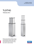
1
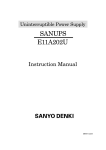
Installation, operation and maintenance manual TMS Telescopic pillar Read this manual before installing, operating or maintaining this actuator. Failure to follow safety precautions and instructions could cause actuator failure and result in serious injury, death or property damage. Technical Instructions TMS Telescopic Actuator Contents 1 General Information . . . . . . . . . . . . . . . . . . . . . . . . . . . . . . . . . . . . . . . .2 1.1 Usage of Technical Instructions . . . . . . . . . . . . . . . . . . . . . . . . . . . . . . . . . . . .2 1.2 Explanation of Symbols . . . . . . . . . . . . . . . . . . . . . . . . . . . . . . . . . . . . . . . . . .2 1.3 Proper Usage . . . . . . . . . . . . . . . . . . . . . . . . . . . . . . . . . . . . . . . . . . . . . . . . . .2 1.4 Ambient conditions . . . . . . . . . . . . . . . . . . . . . . . . . . . . . . . . . . . . . . . . . . . . .2 2 Function . . . . . . . . . . . . . . . . . . . . . . . . . . . . . . . . . . . . . . . . . . . . . . . . .3 2.1 TMS Telescopic Actuator Function Description . . . . . . . . . . . . . . . . . . . . . . . .3 2.2 Design . . . . . . . . . . . . . . . . . . . . . . . . . . . . . . . . . . . . . . . . . . . . . . . . . . . . . . .4 3 Assembly and Commissioning . . . . . . . . . . . . . . . . . . . . . . . . . . . . . . . . . .5 3.1 Included in the Shipment . . . . . . . . . . . . . . . . . . . . . . . . . . . . . . . . . . . . . . . .5 3.2 Assembly . . . . . . . . . . . . . . . . . . . . . . . . . . . . . . . . . . . . . . . . . . . . . . . . . . . . .6 3.3 Electrical Connection . . . . . . . . . . . . . . . . . . . . . . . . . . . . . . . . . . . . . . . . . . . .8 3.4 Commissioning . . . . . . . . . . . . . . . . . . . . . . . . . . . . . . . . . . . . . . . . . . . . . . . .10 4 Operation . . . . . . . . . . . . . . . . . . . . . . . . . . . . . . . . . . . . . . . . . . . . . . .11 4.1 Controlling the TMS10 EASY Type Drive . . . . . . . . . . . . . . . . . . . . . . . . . . . .11 4.2 Controlling the TMS00 MECHANICAL Type Drive . . . . . . . . . . . . . . . . . . . . .12 5 Service and Maintenance . . . . . . . . . . . . . . . . . . . . . . . . . . . . . . . . . . . .13 5.1 Service . . . . . . . . . . . . . . . . . . . . . . . . . . . . . . . . . . . . . . . . . . . . . . . . . . . . . .13 5.2 Maintenance . . . . . . . . . . . . . . . . . . . . . . . . . . . . . . . . . . . . . . . . . . . . . . . . .14 5.3 Guaranty . . . . . . . . . . . . . . . . . . . . . . . . . . . . . . . . . . . . . . . . . . . . . . . . . . . .14 5.4 Disposal . . . . . . . . . . . . . . . . . . . . . . . . . . . . . . . . . . . . . . . . . . . . . . . . . . . . .14 5.5 Liability . . . . . . . . . . . . . . . . . . . . . . . . . . . . . . . . . . . . . . . . . . . . . . . . . . . . .14 6 Technical Information . . . . . . . . . . . . . . . . . . . . . . . . . . . . . . . . . . . . . .15 6.1 Dimensional Drawings TMS10 EASY Type . . . . . . . . . . . . . . . . . . . . . . . . . . .16 6.2 Dimensional Drawings TMS00 MECHANICAL Type . . . . . . . . . . . . . . . . . . . .17 7 Troubleshooting and Fault Remedies . . . . . . . . . . . . . . . . . . . . . . . . . . . .18 Standards applied UL 2601 EN 60601-1 SKF Actuation System (Liestal) AG Oristalstrasse 97 CH-4410 Liestal Phone +41 61 925 41 11 Fax +41 61 921 37 04 E-mail [email protected] Web www.skf.com L5312,4100E.2/05.03 Technical Instructions TMS Telescopic Drive 1 General Information 1.1 Usage of Technical Instructions The Technical Instructions are aimed at design engineers or specialists who use the TMS telescopic actuator (hereafter referred to as “TMS”) in their products as well as fitters who install the drive. The technical information contains all relevant instructions on this Magnetic product. Subject to modifications in the interest of technical progress. Please read the technical instructions carefully and follow the safety instructions. The Technical Instructions must also be used when drafting the user manual for the end product particularly those instructions which involve the safe use of the product. This symbol identifies actions and conditions which can be hazardous to people or property. Follow the instructions exactly! 1.2 Explanation of Symbols Potential hazards and important instructions are identified with the symbols to the left. This symbol identifies helpful or useful instructions for the user. 1.3 The TMS telescopic drive may not be operated in an atmosphere with danger of explosion. For transport purposes, the TMS can temporarily be loaded with max. 1000 N of tension. The maximum load specified on the name plate as well as the permissible eccentric load according to the asymmetrical load diagram may not be exceeded. Non-compliance can result in destruction of the drive. Proper Usage The TMS is especially designed to position examination tables for diagnosis and is in conformity with standards EN60601-1, and UL2601. The TMS may only be subjected to one pressure load. Tensile forces may not affect it. The TMS telescopic actuator is only appropriate for internal applications and may not be exposed to the elements. The open construction requires safety device or a cover which protects people from catching body parts and the machine from contamination. In the end application, the machine should be protected from contact and contamination. Otherwise, the service life can be reduced. 1.4 Ambient conditions Operation: • Temperature +10°C to +40°C • Air moisture max. 85% Storage/Transport: L5312,4100E.2/05.03 • Temperature -20°C to +40°C • Air moisture max. 95% Magnetic – The Linear Drives Company™ Page 2/18 Technical Instructions TMS Telescopic Drive 2 Function 2.1 TMS Telescopic Actuator Function Description 2.1.1 Guidance System The lifting element was especially designed for small-dimension installations and large eccentric loads. The possible stroke with minimum assembly dimensions is achieved through two parallel and telescopic linear guides. These linear guides (guidance system with circulation balls) are reinforced with special aluminum profiles. The double telescopic arrangement of the linear guides achieves an optimal stroke - overall dimension ratio. (Assembly dimension = 1⁄2 stroke + 176 mm) 2.1.2 Drive Unit for TMS10 EASY Type The stroke motion occurs with two parallel spindle systems. One spindle system consists of a ball screw spindle, a motion nut, a DC motor and a wrap spring brake. The motion nuts on the two spindle systems are attached to the middle section. One motor spindle configuration mounted to the upper mounting plate and the bottom plate. Each of the spindle systems takes on one half of the life and the speed of the entire stroke system. The motion nuts (ball nuts) only have one safety catch nut which stops the system in the case of a total failure and prevents a reduction of the load. The two DC motors are operated by a control system (COM6). 2.1.3 Drive Unit for TMS00 MECHANICAL Type The MECHANICAL drive unit works in essentially the same way as the EASY drive unit. The difference is that the MECHANICAL drive system has no electrical drive of its own. The user must install his own drive. The system consists of two spindle systems and a double worm gear. The gear drives the two motion nuts which run on the ball screw spindles The ball screw spindles are attached on the upper mounting plate and the bottom plate. 2.1.4 Operating Principles for the Control of the TMS10 EASY Drive The main process of the COM6 control unit controls and regulates the connected motors. The functions in the control program are activated with the hand control (EHE6), foot control (STH), and locking device (SPP6). The functions, connector pin assignments and options for a control unit are configured ex works according to the system manufacturer requirements and cannot be changed afterwards. Separate customer-specific documentation is enclosed with these Technical Instructions if necessary. An integrated over-current cut-off protects the connected motors from overload. Power Supply (Insulation class II with Function Ground) The power voltage is transformed to a low voltage of 24 V with a thermally protected main transformer. The integrated rectifier transforms it into DC voltage. Economy Circuit (Stand-By) When the drives are in non-operating mode, an auxiliary transformer maintains the control supply voltage. The main transformer is automatically switched off and is thereby thermally relieved. First Fault Safety To ensure first fault safety, the critical safety components are equipped with control and additional functions. For detailed information, please see the Technical Instructions of the COM6 control unit, available upon request. L5312,4100E.2/05.03 Magnetic – The Linear Drives Company™ Page 3/18 Technical Instructions TMS Telescopic Drive 2.2 Design EASY TMS10 Type The EASY model is based on 2 DC motors which directly power a spindle on which the screw nuts run. The end position shut-off is activated by the limit switch. In order to achieve a small assembly dimension with a large stroke, the two drive units are coupled to the middle section via a plate. Protection against thermal or dynamic overload is only guaranteed when a Magnetic control unit is connected. The supply cable is fixed to the telescopic actuator in the EASY model. The DC drives are protected from thermal and electrical loads by the connected Magnetic control unit. MECHANICAL TMS00 Type The MECHANICAL model is based on a double worm gear which drives two extension tubes into which the screw nuts are permanently fixed. The screw nuts run on the fixed mounted spindle units. The MECHANICAL model does not include a drive and a control unit. It is the user's responsibility to define an adequate drive and control system which meets his needs. Here the requirements indicated in chapter 3.2.4 must be taken into consideration. Control System of the TMS10 EASY Type Drive The first fault safety of the complete system must be checked in the end unit to rule out any possible hazards to persons or property The D.C. motor is supplied with power via an external Magnetic control system. These components determine the polarity of the D.C. voltage and the running direction of the drive. The drive is activated via the control unit and the connected control elements. During a first fault it is possible that the unit can come to a stop and can not be set again! The drive has extensive protection against faults. However, first fault safety cannot be guaranteed because unforeseeable defects, e.g. of a control element, can result in slow, uncontrolled movements. Operating Mode When the on time is too long, a temporary function failure can occur in the TMS. When the drive has cooled, the power cable must be unplugged for 1 minute so that the electrical self-lock of the thermal switch can reset. L5312,4100E.2/05.03 • intermittent 10%; 1 min ON / 9 min OFF The drive is designed for intermittent operation. When in use for a longer duty cycle, please contact Magnetic AG, Liestal. The EASY type drive is thermally protected by the COM6 control unit. A thermal switch built into the transformer winding switches of the drive off at an elevated temperature with an electrical lock. Magnetic – The Linear Drives Company™ Page 4/18 Technical Instructions TMS Telescopic Drive 3 Assembly and Commissioning 3.1 Included in the Shipment The TMS drive consists of: Protective low voltage (SELV) is the standard for the TMS. With the optional power cable feed-through, a protective class I or II designation is not given because it is strictly a cable feed and is not connected to the unit. The power cable feed must be protected with 2 x 6,3 A fuses All metal parts have no connection with the protective conductor. • the complete lifting column • 2 transport hooks Optional Features: • Power cable feed-through (max. load 250 V / 50 – 60 Hz; 6 A) The protective earth conductor is only fed through and not connected to the metal parts of the telescope column. • Control connection, fed through • Cable potentiometer • Limit switch for the TMS00 MECHANICAL type drive Accessories • Hand control (EHE), Table control, foot control (Comfodesk) • Compensation plate below item No. 307362 • Compensation plate above item No. 307361 156 130 A 18 B 100 A B B B 40 85 25 B A A 15 30 36 B A = Ø 22 mm B = Ø 15 mm A 25 30 B 53 30 B 15 B A 170 45 30 85 15 25 35 185 200 With the cable feed-through option, care must be taken to guaranty that this cable is not pinched into the end unit during and after installation. Danger of electric shock! A 70 A B B 40 25 Top 60 300 Fig. 1. Dimensions of upper compensation plate (All dimensions in MM) 100 15 A 30 25 15 35 B A 120 53 B A B 40 18 90 B B 26 15 15 A 130 170 B A = Ø 22 mm B = Ø 15 mm 46 Down A B 40 A B A 40 210 80 A B B 40 120 200 60 311 90 15 40 130 670 Fig. 2. Dimensions of lower compensation plate (All dimensions in MM) L5312,4100E.2/05.03 Magnetic – The Linear Drives Company™ Page 5/18 Technical Instructions TMS Telescopic Drive 3.2 Assembly The main load direction of the TMS is the X direction. This should be kept in mind during installation. The load values are shown in chapter 6, Technical Information: Y X X Y Fig. 3. Main load direction X 3.2.1 Attachment of the Bottom Plate The stroke element must be fixed to the ground before commissioning. Here the lifting element is placed onto the lower steel plate (bottom plate). During assembly, the elements above such as the screw heads and the spindle end on the ground must be relieved or the compensation plate (item No. 307362, cf. Fig. 2) is place between the ground and the bottom plate. It is essential that the locked areas in Fig. 4 be supported for power transmission. There are through-holes in bottom plate 8 for attachment with a diameter of 13 mm, which should all be used with M12-8.8. screws. A minimal screw reach of 25 mm and a screw stud torque of min. 70 Nm must be maintained. 317 304 269 45 90 96 B 170 A = Ø 22 mm B = Ø 15 mm C = Ø 30 mm D = Ø 40 mm 18 C 35 B B B B 38 B B A A A A 30 B D 130 A 53 B A 100 58 10 B 15 B 59 200 24 90 15 15 49 A B B 40 B 40 28 Down A B B B 40 290 40 90 670 Fig. 4. Dimensions of bottom plate (Dimensions in MM) (Locked area must be supported, cf. also Fig. 2) L5312,4100E.2/05.03 Magnetic – The Linear Drives Company™ Page 6/18 Technical Instructions TMS Telescopic Drive 3.2.2 Attachment to the Upper Mounting Plate Attachment to the upper mounting place occurs under the same conditions as described in point 3.2.1. During assembly the elements above such as the screw heads and the spindle end on the upper mounting element should be relieved or the compensation plate (item No. 307361, cf. Fig. 1) is placed between the ground and the bottom user-side mounting element. The locked areas in Fig. 5 must be supported for power transmission. 670 156 45 35 B B B 28 A 25 B A A 14 30 B B C 130 170 A B B 119 B 25 B A 30 B 40 105 200 A 100 B 53 B 18 30 58 15 25 35 185 A = Ø 22 mm B = Ø 15 mm C = Ø 30 mm A A B B 40 25 Top 90 300 Fig. 5. Dimensions of upper mounting plate (Dimensions in MM) (Locked area must be supported, cf. also Fig. 1) 3.2.3 Assembly of the Control Unit for the TMS10 EASY Type The COM6 control unit is mounted to the four holes provided (Fig. 6). All positions are possible. Care must be taken when laying the supply cables that no line can get caught in the lifting element. (High catching and shearing danger). 5 9 13 32 7 10 80 3 36 40 0 75 11 1 Fig. 6. Overall dimensions COM6 control unit L5312,4100E.2/05.03 Magnetic – The Linear Drives Company™ Page 7/18 Technical Instructions TMS Telescopic Drive 3.2.4 Assembly of a Drive Motor with the TMS00 MECHANICAL Type The user installs the drive motor with the MECHANICAL model. The The connection between the drive shaft and the motor shaft must be done with a flexible coupling. The connection dimensions are shown in the dimension drawing (cf. chapter 6, Technical Information). The maximum torque of 0.9 Nm at 6000 rpm, which can be fed into the gear, must be maintained. 100 LK Ø M6 Ø12 g6 4 P9 5 107 4 x M6 3 12,6 A 1 6 10 A-A Ø80 +0,1 0 LK Ø100 x10d eep A Fig. 7. Flange dimensions type TMS00 for connection to a motor The connecting cable to the motor has to be laid so that it can run through one half of the lifting height with the drive (e.g. spiral cable). When routing the cable care should be taken that no line could get caught or sheared. 3.3 The power cable must be accessible at all times in order to unplug the system from the power supply in the event of failures. Electrical Connection Connecting the Power Cable The supply voltage must correspond to that indicated in the control unit technical information. Otherwise, the control unit can be destroyed or not function. 2 1 Fig. 8. Power cable connection Plug in the power cable into the left jack of the control unit. If the control unit is connected to the power supply, the power voltage display illuminates with a (2) green light. L5312,4100E.2/05.03 Magnetic – The Linear Drives Company™ Page 8/18 Technical Instructions TMS Telescopic Drive Connecting the Control Element(s) Fig. 9. Connection of a control element Plug the D-SUB connector of the control element into the control unit jack provided (Fig. 8). Which control elements are used depends on the system manufacturer requirements. Please follow the instructions in the separate customer-specific documentation. In Fig. 8, for example, hand control EHE6 is shown. Ensure that the connectors are plugged in correctly in the right position. Otherwise the plug in the unit can be destroyed. Note shape of connector and arrows (must be on one side) Fig. 10. Connector for control element (Note arrows) When plugged in, the cables are strain-relieved and sealed by the integrally cast cams. The cams lock into the locking clamp. Connecting the Drives and Limit Switch Fig. 11. Connections for drives The drives and limit switch are strain-relieved and must be connected in the following way: 1. Plug in the connector (the sealing rings may no longer be visible). 2. Insert special key No. 140375. 3. Interlock the special key by moving it 30° to the right against the end stop (cf. Fig. 12). L5312,4100E.2/05.03 Magnetic – The Linear Drives Company™ Page 9/18 Technical Instructions TMS Telescopic Drive Fig. 12. Connecting drives 3.4 Commissioning The lifting column is ready for operation after correct electrical and mechanical connection is completed. An initialization run must be carried out once before the TMS can be used: Initialization Run If the initialization run is not implemented, there is no guaranty that the full stroke will run. L5312,4100E.2/05.03 Move the drives to the lower end position (reference point) using the direction buttons. Hold down the control button until all drives have reached the end position and come to a stop. Magnetic – The Linear Drives Company™ Page 10/18 Technical Instructions TMS Telescopic Drive 4 When operating the drive, care should be taken that no objects or body parts can get caught. Danger of injury! In the end application, the unit should be protected against contact and contamination. Otherwise the service life of the unit can be reduced. Operation During operation, the drive must be protected with a proper cover to prevent body parts or objects from getting caught in the machine. The drives can be operated with different control elements depending on the requirements (cf. 3.1 Accessories). The following figures, for example, illustrates the operation of hand control EHE6. 4.1 Controlling the TMS10 EASY Type Drive In the event of a fault, there is no guaranty that the profiles will extend and retract equally and simultaneously A P2 M P1 P3 B Fig. 13. Hand control EHE6 The drives can be directly controlled with the buttons in area A (Fig. 12) of the hand control. • Button : The drive extends • Button : The drive retracts The drive retracts Using buttons P1 to P3 of the hand control (Fig. 12, area B), positions can be reached which were pre-programmed in the control unit. Here is how to save the desired positions: 1. Using the buttons and , run all of the drives to the position which you would like to save under button P1 (Hold down the buttons until the desired position has been reached.) 2. Press the M button and hold it down and also press button P1. 3. Release both buttons simultaneously. Information being saved is confirmed by an acoustic signal. 4. Repeat steps 1 to 3 to program the buttons P2 and P3 if necessary. Recalling the memory positions To recall the memory position, press the corresponding button P1, P2 or P3 of the hand control (Fig. 12, area B) Hold the button down until the drives have reached their desired position. L5312,4100E.2/05.03 Magnetic – The Linear Drives Company™ Page 11/18 Technical Instructions TMS Telescopic Drive 4.2 The maximum torque on the shaft entrance may not exceed 0.9 Nm. Only in the case of a fault should the drive run onto the safety bolts. Otherwise the service life will be reduced or the drive can be destroyed. Controlling the TMS00 MECHANICAL Type Drive To control the MECHANICAL drive, an appropriate control system can be used for the selected drive. It should be kept in mind that the control unit should be equipped with a torque monitoring device. The maximum torque of 0.9 Nm may not be exceeded. Otherwise the service life can be reduced or the drive can be destroyed. The control unit must also ensure that the safety bolts should only be reached in the case of a fault and the fault condition is recognized. L5312,4100E.2/05.03 Magnetic – The Linear Drives Company™ Page 12/18 Technical Instructions TMS Telescopic Drive 5 Service and Maintenance 5.1 Service The TMS telescopic actuator is designed for a service life of 10 years or a 16,000 m running distance (with a maximum load according to the name plate/ load diagram). During this time, the drive is service-free. The drive should only be opened and serviced by Magnetic Customer Service! If there are other requirements on the service life, self-tests are to be performed. After achieving a service life of 10 years, the drive must be returned to the manufacturer for revision. Removing the Plug-in Connectors Fig. 14. Removing power and unit connectors To remove a power or unit connection cable from the control unit, the clamps must be spread open with special key No. 140375. This is the way remove the plug (cf. Fig. 13). (There is an opening for the special key in the power, unit, and drive plugs.) To remove the drive connector, proceed according to Fig. 14. 1. Insert special key No. 140375 and turn it approx. 30° to the left and unlock the plug (cf. Fig. 14). 2. Remove the connector from the plug. Fig. 15. Removing drive connector L5312,4100E.2/05.03 Magnetic – The Linear Drives Company™ Page 13/18 Technical Instructions TMS Telescopic Drive 5.2 Maintenance Protection against Water, Cleaning, Disinfection Care should be taken that no liquid gets into the drive! The drive could be destroyed by the penetration of liquid. The unit is not protected against penetration by water. The drive can neither be cleaned nor sterilized. 5.3 Even in the case of contamination, the drive may not be cleaned. Otherwise, the service life is reduced. Guaranty Provided that the operated conditions have been followed and the units show no mechanical damage due to improper usage, the guaranty is in effect for 24 periods after date of invoice for all mechanical and electrical components. 5.4 Disposal The control components and drives can be returned to Magnetic AG for disposal. 5.5 Liability Liability for the function of the unit is transferred in any case to the owner or operate if the unit was incorrectly installed, serviced , or maintained by persons who are not Magnetic service personnel or if an action is performed which is considered inappropriate usage. Magnetic AG is not liable for non-compliance with the above instructions. The guaranty and liability conditions of the General Sale and Delivery Conditions of Magnetic AG are not extended by the instructions above. L5312,4100E.2/05.03 Magnetic – The Linear Drives Company™ Page 14/18 Technical Instructions TMS Telescopic Drive 6 Unit Versions Technical Information TMS10 EASY TMS00 MECHANICAL Stand alone Stand alone Push force (max.) N 4000 4000 Torque Nm 3000 3000 intermittent 10%, 1 min ON / 9 min OFF intermittent 10% 1 min ON / 9 min OFF Operating mode Speed mm/s 16 – 28 20 at 6000 RPM Stroke (in increments of 100) mm 300 – 700 300 – 700 Retracted length mm 326 – 526 326 – 526 Voltage V / Hz 24 DC — Current input A (DC) 2x6 — Torque drive shaft Nm — max. 0.9 Nm SELV — 300 mm stroke: 64 400 mm stroke: 70 500 mm stroke: 75 600 mm stroke: 80 700 mm stroke: 85 300 mm stroke: 61 400 mm stroke: 67 500 mm stroke: 72 600 mm stroke: 77 700 mm stroke: 82 Protective system /protection class Weight kg The manufacturer reserves the right to adjust the technical information without any special announcement to reflect technical progress. Magnetic AG, Liestal is happy to provide information on up-dates, modifications or supplements. L5312,4100E.2/05.03 Magnetic – The Linear Drives Company™ Page 15/18 Technical Instructions TMS Telescopic Drive 5 Dimensional Drawings TMS10 EASY Type 355 6.1 30 30 670 15 90 460 25 30 30 25 15 13 90 300 185 25 10 142 156 40 45 10 130 170 119 130 200 14 170 37 82 40 35 13 40 25 35 15 35 18 40 Fig. 16. TMS dimensional drawing TMS10 Easy type drive (Dimensions in MM; 1 mm= 0.0394 inch) L5312,4100E.2/05.03 Magnetic – The Linear Drives Company™ Page 16/18 Technical Instructions TMS Telescopic Drive 6.2 5 5 8 7 A Dimensional Drawings TMS00 MECHANICAL Type 100 LK Ø A x10d eep 1/2 Hub + 176 M6 A A-A 10 5 107 30 8 Ø80 +0,1 0 30 7 4 P9 3 12,6 Ø12 g6 5 1 6 10 A 4 x M6 Ø18 LK Ø100 670 15 90 460 25 30 30 25 15 13 90 300 185 40 25 45 10 10 142 156 130 170 119 130 170 14 200 37 82 40 35 13 40 25 35 15 35 18 40 Fig. 17. TMS dimensional drawing TMS00 MECHANICAL type drive (Dimensions in MM; 1 mm = 0,02394 inch) L5312,4100E.2/05.03 Magnetic – The Linear Drives Company™ Page 17/18 Technical Instructions TMS Telescopic Drive 7 All work on the units and connectors should only be performed when the power cable is unplugged. Troubleshooting and Fault Remedies Fault Cause Remedy Only for drives with power supply (master / stand-alone) Drive does not function No power supply Check power supply Poor connector contact Plug in power cable correctly or check clamp connection Plug in control element connector correctly Power cable defective Replace power cable Control element defective Replace control element Internal fuse in control unit defective Send drive to Magnetic service Motor defective Send drive to Magnetic service Drive only runs in one direction Switch-off mechanism is jammed Send drive to Magnetic service Individual function does not work Memory loss Move drive to reference point (initialization run) cf. 3.4 Commissioning Greatly reduced speed Motor, drive or nut defective Send drive immediately to Magnetic service Greatly increased operating noises Motor, drive or nut defective Send drive immediately to Magnetic service Clearance in the guidance Wear to the sliding system elements or overload Send drive to Magnetic service Also follow the directions in the customer-specific documentation. If you should be unable to remedy a fault, please contact Magnetic AG, Liestal. Additional information is available from our data sheet: Telescopic Drives TMS10 EASY / TMS00 MECHANICAL L5322,4100E L5312,4100E.2/05.03 Magnetic – The Linear Drives Company™ Page 18/18