1
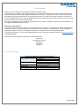
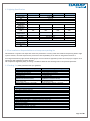
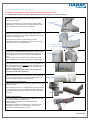
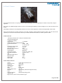
SL700 Series Operating Theatre Light System Including optional SL 7 camera User Manual & Installation Guide QAM.SL700LED.0915.9 Page 1 of 39 Contents 1. Introduction ........................................................................... 3 1.1 Supported Lights ................................................................. 3 1.2 Lighting Specification ........................................................... 4 1.3 Pre-Installation Responsibilities and component packing list ............ 4 1.4 Packing List ....................................................................... 4 1.5 Essential adjustment information ............................................. 6 2. Operation Guide Section ............................................................. 7 2.1 Range of Motion .................................................................. 8 2.2 Pre-Start Checks.................................................................. 9 2.3 Battery Back-up .................................................................. 9 2.4 Powering On & Variable Intensity ............................................. 9 2.5 Adjusting the Lighthead........................................................10 2.6 The SL7 Camera .................................................................11 2.7 How to operate the Monitor and Camera Attachments ..................12 3. Installation Guide Section ..........................................................13 3.1 Considerations ...................................................................14 3.2 Ceiling Mounted Lights .........................................................15 3.2.1 Attachment methods and void suspension ...............................15 3.3 Lighting configuration ..........................................................15 3.3.1 Affixing the Ceiling plate ....................................................15 3.3.2 Wiring and transformer layout .............................................16 3.3.3 Fixing the arms and main installation.....................................18 3.3.4 Mounting the Monitor Bracket ..............................................19 3.3.5 Lighthead Attachment .......................................................21 3.3.6 Lights with Camera’s and monitor displays ..............................23 3.3.7 Attaching the Camera ........................................................24 3.3.8 Attaching the Ceiling Cover .................................................25 3.4 Wall Mounted Bracket Assembly ..............................................26 3.4.1 Considerations.................................................................26 3.4.2 Placement and Installation .................................................27 3.5 Mobile Mount Assembly ........................................................30 4. Maintenance ..........................................................................33 4.1 Maintenance schedule ..........................................................33 4.2 Safety Precautions ..............................................................33 4.3 Cleaning...........................................................................33 4.4 Fuses and their replacement ..................................................33 4.5 Adjustments ......................................................................34 4.5.1 Ceiling and Wall Mounted Adjustments ...................................34 4.5.2 Mobile Adjustments ..........................................................35 4.5.3 Replacing the LED Bulbs .....................................................35 5. Troubleshooting Guide ..............................................................36 6. Camera & Monitor Troubleshooting Guide ......................................37 7. Replacement Parts ..................................................................37 8. Warranty Information ...............................................................38 8.1 Returns Policy....................................................................38 8.2 Warranty Details ................................................................39 Page 2 of 39 1. Introduction Thank you for choosing a Daray SL700 Series Operating Theatre Light. The SL700 Series of lights are specifically designed to meet the demanding needs of today’s medical department whilst providing the finest quality design with superior performance, reliability and value. This manual has been provided to give detailed descriptions covering the performance, operation and safety information of the device. It’s recommended that users read through this manual before using the device so they are aware of how to operate the device and all of its features appropriately. This user & installation guide contains all the information you need for installation, operation and maintenance of the lights and additional camera option. Restrictions and Liabilities Information in this document is subject to change and does not represent a commitment by DARAY. Changes made to the information in this document will be incorporated in new editions of the publication. No responsibility is assumed by DARAY for the use or reliability of software or equipment that is not supplied by DARAY For further information on our product range and find out more about our company please visit www.daray.co.uk or call 0333 321 0971 This product was designed & manufactured in Great Britain by: Daray Ltd. Marquis Drive, Moira Swadlincote Derbyshire DE12 6EJ 1.1 Supported Lights Sl750 SL770 SL750 SL750 SL770 The Following Models are supported in this Manual Ceiling Mounted Wall Mounted Mobile Mounted Ceiling Mounted Wall Mounted / 770 Double Ceiling Mounted / 750 Double Ceiling Mounted / 770 Double Ceiling Mounted Page 3 of 39 1.2 Lighting Specification Luminance Lx SL770/SL770LED SL750/SL770LED SL770LED SL750LED 40,000~160,000 30,000~160,000 40,000~160,000 30,000~120,000 Colour Temp 3,600~5,500 CRI Up to 95 R9 90 R13 Spot diameter (d50) mm Spot diameter (d10) mm Focusing depth mm Irradiancy L400nm W/m2 Number of LEDs 93 120 120 120 120 240 240 240 240 1000 1000 1000 1000 400nm≤0.002 002≤0.002 400nm≤0.002 002≤0.002 120 105 60 45 1 W/pc x 60pcs 1 W/pc x 45pcs Focusing LED power W Manual/Electric 1 W/pc x 60pcs 1 W/pc x 45pcs Power supply 220V 50Hz Input power Average service life 300W 50,000 hours 1.3 Pre-Installation Responsibilities and component packing list This document is a guide to the steps that need to be performed to correctly install the SL700 Series Operating Theatre Light System. However, the work required to be performed is the responsibility of the owner or designated contractor/s. All fixings between Daray lights and the building super-structure must be approved by either the chief project engineer or an appropriate and competent structural assessor. The components supplied by Daray for fitting / installation should be the following items in the specified quantities. 1.4 Packing List (what you should have per lighthead). SL770 Ceiling Mounted Light 1 Primary Lighthead 1 Fixing Plate 1 Ceiling plate with pedestal 1 Primary Rotation Arm 1 Suspension Arm 1 Digital Touch Screen (pre-attached to each lighthead and a third arm section) 2 Ceiling Mount Cover Halves + 1 securing ring for the ceiling cover (Optional Battery back-up, 1 per head) SL750 Ceiling Mounted Light 1 Primary Lighthead 1 Fixing Plate 1 Ceiling plate with pedestal 1 Primary Rotation Arm 1 Suspension Arm 1 Digital Touch Screen (pre-attached to each lighthead on a third arm section) 2 Ceiling Mount Cover Halves + 1 securing ring for the ceiling cover (Optional Battery back-up, 1 per head) SL700 Series Dual Mounted Ceiling Light with camera and monitor 1 Primary Lighthead 1 Secondary Lighthead (satellite) 1 Fixing Plate 1 Ceiling plate with triple arm downtube, pre-wired transformers and a central chock block 1 HD Camera 3 Primary Rotation Arms (pre-assembled with 2 pre-attached suspension arms) 1 loose Suspension arm 2 digital touch screens (pre-attached to each lighthead) 2 Ceiling Mount Cover Halves + 1 securing ring for the ceiling cover 1 monitor mounting arm with bracket 1 Touch Screen Monitor 1 Bag of inter-arm fixings and spare connectors (Optional Battery back-up, 1 per arm) 1 Autoclavable handle (2 for lights without camera’s) Page 4 of 39 SL750 Mobile Mounted Pack List Lighthead Mobile Base with 4 caster lockable wheels Lower vertical tubing Upper vertical tubing Suspension Arm IEC Power Lead SL750 Wall Mounted Pack List 1 Primary Lighthead 1 Wall Mount Bracket with pre-attached transformer and rotation arm 1 Suspension Arm 1 Wall Mount Cover SL770 Wall Mounted Pack List 1 Primary Lighthead 1 Wall Mount Bracket with pre-attached transformer and rotation arm 1 Suspension Arm 1 Wall Mount Cover The ceiling mounted edition of the SL700 series lights has a recommended fixing point of 3 metres from the floor; the minimum height is 2.7m and maximum of 3.3m. Anything over this height or systems using multiple satellites, will require a customised length of downtube. Please contact Daray for further information. Standard installation height: Safety type: Working as: Temperature: Relative humidity: Power supply: Frequency: 3m Kind I, type B Continuous operation 10℃—30℃ 10%—80% 220V AC ±10% 50Hz±1% Page 5 of 39 1.5 Essential adjustment information PLEASE NOTE: THE SUSPENSION ARM IS SENT OUT IN A LOCKED HEIGHT POSITION For a detailed description of all these adjustments, please refer to page 34 of this user manual. Rotation arm Rotation arms are adjusted using tension points located on the central arm boss. There are two brakes, one on each side of the unit; When adjusting this tension ensure you use equal braking on each side as favouring one side could cause damage. Tension grub screws Suspension arm Horizontal drift (sideways) is controlled by a pair of Hex screws on the front side of the spigot joint that connects the rotation and suspension arms. tension points Vertical drift (up/down) is controlled by a tension adjustment located in a keyhole slot under the same spigot joint mentioned for the horizontal drift Vertical Tension Adjustment Suspension Arm height PLEASE NOTE: THE SUSPENSION ARM HEIGHT IS SENT LOCKED The height of the arm is adjusted using a keyhole hex point in the end of the arm where it connects to the lighthead arm. Once the light is fully installed, insert a hex tool into this hole to adjust the arms range of movement / upper height. Lighthead hinge arm The lighthead’s are on a separate arm section, movement of this arm is adjusted via the central grub screw located on the hinge behind the control panel on the arm, this should be adjusted using a hex tool. Note: only adjust the central grub screw, the outer two are tied to the assembly of the arm Lighthead turning lighthead itself has one final tension point, this is located at the base of the head where it attaches to the tertiary arm system, and this can be seen pictured below Wall mounted arm adjustments Wall mounted systems use the same arm design as the ceiling mounted version. The main difference in arm configuration for the wall system is the suspension arm/tertiary arm tensions point. This joint is controlled via a grub screw mechanic located underneath the joint. Mobile arm adjustments Mobile edition has no Horizontal drift adjustment as the arm is in a fixed location of a mobile base. Vertical drift is controlled in the same keyhole slot mentioned above Suspension / Tertiary arm tension point is the same as the wall mounted edition; it is controlled via a grub screw mechanic located underneath the joint. Page 6 of 39 2. Operation Guide Section Page 7 of 39 2.1 Range of Motion Downtube Secondary Rotation Arm Primary Rotation Arm Ceiling Cover over the ceiling plate Control Panel Lighthead Suspension Arm Autoclavable Handle or Camera The full range of motion between the SL700 series varies dependent on mounting. This is an image depicting the range of motion on a double ceiling mount fitting. Page 8 of 39 2.2 Pre-Start Checks Please check (when applicable) that the head and arms are without visible damage, and all LED’s are present in the head. Please note, the SL700 series may take a few seconds to power on fully and illuminate, please be patient when first turning on the light. Users should not look directly into the light as it is bright and will illuminate when powering on. Please check (when using the mobile version) that the power cable is without visible damage, harsh folds, knots or cuts in the rubberised coating. If you are using a mobile version; check that the cable is fully connected to the device and that the plug is fully inserted into the power socket, when switching the power on. 2.3 Battery Back-up The SL700 series has the capability of using a battery back-up system. The battery should be conditioned before being used for the first time. Battery conditioning involves removing all the charge from the battery. Batteries should be conditioned regularly. Condition a battery when the device is stored for long periods, or when the charge becomes noticeably shorter. Follow the steps below to condition a battery: 1. Disconnect the battery from the light. 2. Attach the battery in need of conditioning to a suitable electrical supply. 3. Charge the device uninterrupted for up to 10 hours. 4. Disconnect the electrical supply and re-attach the battery to the light, allow the light (while disconnected from its primary power source) to run on the battery until it shuts off. 5. Charge the battery until fully charged again. 6. The battery is now conditioned. Batteries can deteriorate over time, meaning a reduction in their performance. To check the performance of a battery, follow the steps below: 1. Charge the battery uninterrupted for 10 hours. 2. Disconnect the mains supply to the light and allow it to run on the battery until it shuts off. 3. The operating time of the light reflects the condition of the battery. Replace the battery if the operating time is significantly lower than the specified time. 2.4 Powering On & Variable Intensity The SL700 Series uses a microcomputer digital system to control the lighting options of the lights; this system has 10 continuous steps to adjust light intensity, luminance and colour temperature from on-board memory through a control panel located on the arm of the lighthead. Variable Intensity Variable Colour Temperature Power On/Off Light Patch Control NOTE: An icon ∆ is displayed when an LED needs to be replaced, if / when this occurs, please contact DARAY. Ensure mains power is connected to the light and tap the touch screen display; this should then illuminate and display the controls. Press the green button on the display marked with I and O. The light should then illuminate. Page 9 of 39 Use the controls on the display to increase or decrease light intensity (luminance), colour temperature (colour temperature) and the size of the light patch (light spot). To power off the light after use, press the green button on the display marked with I and O again. The display will remain on for a short period, then enter a sleep mode, tap the screen to exit the sleep mode. Please Note, if the light is turned off at a dimmed level, it will remember that level the next time it is turned on, please check the luminance level shown on the control pad. 2.5 Adjusting the Lighthead The SL700 Series lights are secured using a large white, spring balanced and adjustable arm. The head itself has forward and backward motion through the hinge joint connecting the head to the tertiary arm. Lighthead Side Rail Lighthead (Tertiary) Arm The head can be adjusted through use of the rails, located on the side or by the cone in the centre of the head (which can also be used to control the light patch size / focusing depth except when this has been replaced with a camera). Care should be taken not to violently or forcibly adjust the head as this may damage the light. Page 10 of 39 2.6 The SL7 Camera For the SL700 Series there is an option to have a camera attachment, this would typically be located on the primary surgical lighthead. The camera is a 1080P HD digital camera pre-set for auto-focusing and displays real time footage on a 19” TFT-LCD touch screen display. This display is mounted on an independent satellite arm in the central suspension, connected through a BNC coaxial cable. This screen also has built in memory storage to record and “snapshot” footage displayed from the camera. The user also has the capability to access the local hard disc to edit any recorded video data and transfer it to other systems via USB. Camera Features: 1.8v FPGA processor with a 2 GB p/s Transmission Rate 20x Optical Enlargement 3.3 Mega Pixel Quality Image Sensor: 1/2.8 CMOS Adopts Sony VISCA and PELCO Protocols Horizontal Resolution: 1080p / 1080i F= 1.6-3.5, f3.5-85 Horizontal viewing angle: 3.5 – 55.4 View Angle (H/V): 160/160 Minimum Object Distance: 5mm Dot pitch (H*V): 0.297*0.297 Contrast Ratio: 800:01:00 Video Signal Output: HD-SDI, YUV, HDMI, DVI Minimum Illumination: 0.04 Lux / ICR SNR: 50db Operating Temperature: 0-40℃ Response Time: <8ms Digital Input: SDI Power Input: 12v DC Screen Display Features: Screen: 19 inch TFT-LCD touch screen Resolution ratio: 1024 x 768 Brightness: 350ccd/m2 Contrast ratio: 800:1 True colour: 262K MTBF: 50,000 hours Viewing Angle (H/V): 140/120 Material: High intensity aluminium magnesium alloy. Input: 12V/5A Ingress Protection: IP65 (waterproofing grade) Supports USB High-precision, touch screen (resistance-type) Page 11 of 39 2.7 How to operate the Monitor and Camera Attachments The camera has a 5 button control panel on the side. These buttons are used to control the magnification and focusing of the lens. Focus Zoom The left and right controls are used to zoom while the up/down controls are used to focus. Once the installation is complete and the device powers on, the display should directly load into the camera software. This software has a control panel down the right hand side of the screen which can be removed by pressing the 5 th button labelled FullScreen. To get the panel back you will need to double tap the screen. The control panel lists 7 options: Start Recording Snapshot Open Folder Setting FullScreen About Exit Start Recording will start a video recording immediately that is then saved in an MP4 format. This is then saved into the videos sub-folder located by pressing the open folder button. Snapshotting has the same procedure and images taken can be found in another subfolder shown by pressing the Open Folder button. The Monitor itself is defaulted to HD video recording and snapshotting. The hard drive within the monitor is 500Gb and allows many hours of video recording storage without a problem. To remove or modify footage there are USB connections located at the bottom of the monitor. The display can be used in a similar method to a desktop computer. To use the right click mouse option, you will need to double tap the screen. If you press Exit or accidently drop out of the software you will have a red Daray background. To re-enter the software click on the shortcut to Video Recorder, listed on the side of the display. If this does not resolve the issue, please turn the monitor off and on again. Please Note, if a USB drive is left in the USB ports the device will not power on. Page 12 of 39 3. Installation Guide Section Page 13 of 39 3.1 Considerations The ceiling structure must be capable of handling up to a 500kg load. The procedures below are detailed to a high level however If in doubt please consult a qualified electrician. Minimum Room Requirements The SL700 Series ceiling mounted light (single and double) has a standard fixing height of 3.0m. The design works off a fixed plate system and has a large vertical motion with a minimum fixing point of 2.7m. Maximum Room Requirements Please note, if the ceiling / fixing point of the light is above 3.3m then a customised ceiling mount will be required, (please contact Daray for more information). If a suspended ceiling is in the room, you may be able to construct a platform or suitable rigging to lower the ceiling plate’s fixing point to the required height, please note it is recommended to lower the fixing point to the same height as the suspended ceiling. Live Electric Circuitry All personnel working around live circuitry should be qualified and following proper procedures. Heavy or Difficult fittings Fitting the ceiling plate can be difficult and aspects of the fitting may require more than one person; this work should only be attempted by appropriate and competent personnel. Existing Environmental Factors When fitting, considerations have to be taken for existing services such as; fire alarms, vents, lights, etc. along with interior ceiling construction and any surrounding hazard. Environmental Responsibility Once our products are installed all packaging should be disposed of appropriately and recycled where appropriate and in accordance with local governing regulations. The normal life span of the SL700 series is ten years. We recommend the equipment should be discarded and recycled when reaching the end of its life. These instructions are based on the assumption of a fresh fit into a room with no previous lighting structures. With installations onto sites with equipment already in place, we recommend that the previous lights’ mounting plates be removed and the new ones fitted as if into a fresh fitting. Page 14 of 39 3.2 Ceiling Mounted Lights After assessing the structural stability of the ceiling composition it will be necessary to decide on the best installation technique for attaching the ceiling plate. There are various methods that can be used; some examples can be found below: 3.2.1 Attachment methods and void suspension The ceiling mount is split into 2 parts, the fixing plate and the ceiling plate. Please note, the recommended room height allowed for fixing requires the bottom of the ceiling plate to be no lower than 3m. Bolted Directly into a structural slab and secured with chemical bonding This is our primary choice for mounting our lights to the ceiling structure, appropriate rawl bolts and chemical bonding should be used to secure the fitting. Bolted to a Uni-strut Construct When using a uni-strut construct for mounting the ceiling plate, you should ensure that the uni-strut is cross braced to ensure it is secure and does not move. Welded to structure The fixing plate is the component that would be welded to the structure; any welding must be assessed to be capable of handling a 500Kg load. System anchored to composite deck A customised composite deck could be used either in conjunction with or as a replacement to the fixing plate. Any substitute parts must meet safety standards and be assessed by a competent structural assessor. The composite deck is designed to spread the weight of the light over an enlarged area. System bolted to structure This system requires prior planning during the base construction phase of the ceiling above, bolts should be fed through the metal ceiling prior to the concrete base being poured. These bolts should be based on the fixing plate layout in section 3.3.1 3.3 Lighting configuration Dependant on the choice of attachment method, and whether the light is being attached in a void or directly onto an open surface ceiling; custom mounting aspects may be required. Daray’s standard mounting recommendation is to have the fixing plate directly bolted into the structure of an open surface ceiling when possible. Ultimately the mounting method used is the responsibility of the project engineer or fitter. This includes the specification of attachment hardware, lateral bracing and the suitability of the surface to be fixed to. 3.3.1 Affixing the Ceiling plate The location of the light should be decided by the end user / project manager or through schematical drawings. Once the location has been decided it will be necessary to first mark the location of the fixing plate. Fixing Plate Locking Nut Ceiling Plate Adjusting Bolt Ceiling Plate Downtube Page 15 of 39 Fixing Plate As shown, the fixing plate has the bolts for the ceiling plate fixed in place. This piece should be fitted to the ceiling structure of the building. It is highly advisable that the fixing plate is secured with a minimum of 4 bolting points to ensure a complete and sturdy fit. Once the fixing plate is secured, you will need to attach a locking nut to each bolt before attaching the ceiling plate. Now fit the ceiling plate to the fixing plate by sliding the bolts through the securing points on the ceiling plate and attach a 2nd nut (the adjuster nut) to the fixing plate bolts. Locking Nut Adjuster Nut Once the ceiling plate has been fitted, it will be necessary to ensure that it is balanced on the vertical plane. This can be achieved by adjusting the 2nd level of nuts. Once this adjustment has been done tighten the 1st level of nuts (locking nuts) down to the ceiling plate to lock the plate into position. After any adjustment it will be necessary to check that all fixings are still sound and that all nuts are tight. 3.3.2 Wiring and transformer layout Before working on electrical connections please make sure that the power to the light is switched off at the source and secured so that it will not be turned on during your work. The mains power supply should meet IEC60245-1 requirements and should be fitted with a fixed master switch. (The switch should meet IEC328 requirements and the directional movement parts of the switch should meet IEC447 requirements and the symbols should meet IEC60601-1 requirements.) Ideally the cable used to power the light should be of a 1.5mm twin and earth type. Daray recommends that the power supplied uses an earthed switched fused spur, protected with a 3 amp fuse. The wiring should be as follows: Live terminal brown wire. Neutral terminal blue wire. Earth terminal green/yellow wire. The above wiring is for modern wiring applications (post 2000). On completion of the wiring, the next stage will be attaching the suspension arms to the ceiling mount. Wiring between the single mounted and double mounted versions may differ slightly, if you are having a camera attachment and monitor display be careful not to damage to coaxial cable and follow these wiring instructions carefully Page 16 of 39 Double Ceiling Mounted Lights (with Camera and Monitor attachments) Before any cabling can be done you will need to feed the cables up through the ceiling mount and through a hole near the top of the mount, located behind the central wire block (indicated on the image below) feeding these cables through will need to be done while the arm(s) are being mounted at the same time. Using some form of guidance wire secured to the cables may make this easier to install correctly. Cable Hole. This is where you need to feed the low voltage cables and mains feed through Pre-installed Transformer The cables leading to the transformers (from the central choc block) are already attached. These are the 24V transformers used to power the lighthead’s (one per head). You will not need to conduct any electrical wiring on these. The wiring that is fed through the ceiling mount is the only wiring that will need to be connected to either the central terminal block or directly into the mains via a switched fused spur. Feed Mains supply down through the top of the plate and through the cable hole, then connect to the mains feed to the central terminal Insert the mains supply in these 3 contact points The wiring from the arms is labelled and has been paired together with tape. The thin red and black wires are for the 12V DC connections for the monitor and camera. The thicker DC cables are the power leads for the lighthead’s. The coaxial cable runs directly from one arm to the other and isn’t fed through the ceiling mount. The mains supply lead will need to be wired into the central chock block as shown above. There are two other pairs of wires that will need to be attached to the mains supply via a switch fused spur. These are the 12V camera and 12V monitor transformers. Page 17 of 39 3.3.3 Fixing the arms and main installation The downtube provided cannot be adjusted as the primary rotation arms come pre-attached to the downtube which is then inserted into the ceiling mount. Before attaching the arm(s) and the downtube; the ceiling mount must be absolutely true on the vertical plane. Once the parts are ready to be attached it will require 2 or more people to fit, as the cables from the arms need to be fed through the ceiling mount at the same time as the primary arms are attached. Central wiring block Ceiling plate and downtube ‘Arm Boss’ Rotation Arms To lock the arms in place you will need to secure them using 8 screws through the ceiling mount downtube. *there are 4 points on each side of the tube Securing Points Before progressing onto fixing any other arms, ensure that the rotation arms are attached securely. For Monitor and Camera version systems; two of the balance arms come pre-attached to the rotation arms as they have the coaxial cable already fed through them. The third rotation arm that doesn’t have a balance arm attached will be for the satellite lighthead. Page 18 of 39 To attach a balanced suspension arm to the rotation arm you will need to do the following. Prepare the secondary arm by removing the screws in the top and the sides of the spigot section. Within the spigot hole of the rotation arm is the connecting plug for the secondary arm, pull this down from inside the housing gently. This connection will then need to be inserted into the top of the secondary arm spigot and secured in place with screws. With the plug installed securely, you should insert the secondary arm spigot into the primary arm making sure the two hex adjustment points line up with two non-countersunk holes on the outer edge of the spigot housing. With these aligned you will be able to insert the 4 locking screws into the countersunk holes on the sides of the spigot housing. Adjustments to stop drift can be made using the two hex screw points, through the holes, located on the front of the spigot housing. Page 19 of 39 3.3.4 Mounting the Monitor Bracket Once all the balance arms are connected you will need to attach the monitor mounting arm to the rotation arm section closest to the ceiling plate (this is the arm with 1 coaxial cable and 2 smaller wires). To connect this arm section to the suspension arms first remove the screw shown below, this will allow the sliding cover to move, lift this cover up and it will reveal a locking clip round the back, remove this to allow you to attach the arm. Slide Up Sliding Cover securing screw Locking plate under the arm section (at the back) Feed the cables from the suspension arm through the monitor bracket arm. You may also need to feed the cables from the monitor bracket arm down through the bottom of the spigot as well. Re-insert the locking plate to secure the arm and then proceed with connecting the wires ensuring you match the colours / polarities. Sliding Cover securing screw Secure the arm by replacing the locking plate in the back of the arm, slide the cover down and re-fix Bracket mounting spigot Connect the wires as shown (Please note, the coaxial cable connections may differ slightly) Warning, Please observe the Cable Polarities and ensure that they match, incorrectly wiring the device will cause damage to the system Page 20 of 39 Once the cables are connected, feed the cables into the arm joint and place a white cap onto the bottom of the joint. On the back of the monitor are 8 holes, attach the monitor to the bracket using the screws provided. With the monitor Connected, the remaining two suspension arms are for the primary and secondary lighthead’s. These lighthead’s have a third arm already attached and the joints of these are connected to the suspension arms in the same way as the monitor bracket. 3.3.5 Lighthead Attachment The primary lighthead will have the camera attachment and should be mounted on the arm that has the remaining (unconnected) side of the coaxial cable and 4 other wires. The secondary lighthead’s arm will be the one without a coaxial cable and only 2 protruding wires. To connect these arm sections to the suspension arm’s; first, remove the screw shown below. This will allow the sliding cover to move, lift this cover up and it will reveal a locking clip round the back, remove this to allow you to attach the arm. Slide Up Sliding Cover securing screw Locking plate under the arm section (at the back) Page 21 of 39 Feed the cables from the suspension arm down through the tertiary arm spigot. You may also need to feed the cables coming up the tertiary arm, down through the bottom of the spigot as well. Re-insert the locking plate to secure the arm, then proceed with connecting the wires ensuring you match the colours / polarities. Tertiary arm mounting spigot Secure the arm by replacing the locking clip in the back of the arm, slide the cover down and re-fix Sliding Cover securing screw Connect the wires as shown (Please note, the coaxial cable connections may differ slightly) Warning, Please observe the Cable Polarities and ensure that they match, incorrectly wiring the device will cause damage to the system Once the cables are connected, feed the cables into the arm joint and place a white cap onto the bottom of the joint. Repeat for each arm. For the Primary lighthead the camera will need to be attached. Page 22 of 39 3.3.6 Lights with Camera’s and monitor displays For systems using camera’s and monitors the wiring consists of a direct coaxial cable between the camera and the monitor, run through the arm system. Both the camera and the monitor are on a 12V DC system that runs directly into separate transformers by the ceiling mount. Both devices should be attached to DC Jacks which should then be plugged into the cable coming out of the camera circuit board and the DC socket on the bottom of the monitor. Attach the cables from the arms to the DC jack included Warning, Please observe the Cable Polarities and ensure that they match, incorrectly wiring the device will cause damage to the system Insert the DC Jack into the socket labelled on the back of the monitor Connect the two DC jacks The Coaxial Cable Please Note, the internal coaxial connectors may differ from the ones shown in these pictures. Coaxial Cable Page 23 of 39 Once these cables have been connected and secured as directed in section 3.3.3 you will need to attach the coaxial connections to the ports on the camera circuit board, and the bottom of the monitor as shown below. Insert Coaxial Cable into the monitor and camera circuit board, then fix the camera to the lighthead 3.3.7 Attaching the Camera To attach the camera to the lighthead you will need to connect the DC jack mentioned earlier to the DC cables that protrude from the centre of the lighthead, attach the coaxial cable to the circuit board inside the camera head and then plug in the DC jack. Warning, Please observe the Cable Polarities and ensure that they match, incorrectly wiring the device will cause damage to the system Once you have the cables connected align the control panel on the side of the camera to be in line with the bottom of the lighthead to give visibility to the controls for end users to see when they are using the lighting system. Page 24 of 39 3.3.8 Attaching the Ceiling Cover The last aspect of fitting is to attach the ceiling mount cover, this should be done after all the wiring has been checked and the device turns on. The primary cover is split into 2 halves. You will need to place the two halves over the ceiling mount and secure them together using the screws provided. Once the two halves of the primary cover are connected, work the cover over the cabling and then attach the secondary securing ring around the downtube to lock the ceiling mount cover in place. If the head is drifting, or if the movement of the arm is stiff, use a hex tool as indicated in section 4.5 of this manual to tighten the arms. The light can now be tested by applying power and pressing the power button on the back of the head. Check the arm and head for smooth and correct movement. Your new Daray light is now ready for use. To gain full support of our warranty please fill in our warranty web form or contact Daray by phone or email. Daray also provide service plans to help you maintain your light. Contact Daray on 0800 878 9864 for more details. Page 25 of 39 3.4 Wall Mounted Bracket Assembly It is vital that the wall mount bracket is true on the vertical plane as if not, this will cause the light to drift. 3.4.1 Considerations The structure and fixings must be capable of handling excessive torsional loads up to 500kg. Wall Construction Before fixing it is important to consider the strength of the wall and the depth of the fixings used. Use of a building engineer or structural drawings may be required to decide on suitability. Product weight Note, the wall bracket and the rest of the light are heavy. Fixing the Wall bracket may be difficult and require 2 persons to install correctly. We advise that only professional or competent people fit these lights. Product Wiring The mains power supply should meet IEC60245-1 requirements and should be fitted with a fixed master switch. Page 26 of 39 3.4.2 Placement and Installation The wall mount bracket and the primary rotation arm will come pre-attached; to fit this system you will require a minimum of 2 professional fitters. To fix the bracket into position we recommend initially placing it against the wall, aligning it vertically and then drawing drill points onto the wall where the relevant fixing points are located. Drill the holes and then fix the mount while checking the vertical alignment as necessary. Fixing Points Connect the mains supply to the transformer (the cable used to power the light should be of a 1.5mm twin and earth type). Daray recommends that the power supplied uses an earthed switched fused spur, protected with at minimum a 3 amp fuse. The wiring should be as follows: Live terminal brown wire. Neutral terminal blue wire. Earth terminal green/yellow wire. The above wiring is for modern wiring applications (post 2000). The mains power supply should meet IEC60245-1 requirements and should be fitted with a fixed master switch. All components should meet relevant IEC328, IEC447 or IEC60601-1 requirements.) Please note, under no circumstances should you circumvent the transformer and connect this light directly to the Mains electrical supply. Before working on electrical connections please make sure that the power to the light is switched off at the source and secured so that it will not be turned on during your work. To attach the suspension arm to the rotation arm you will first need to remove the circlip locking ring from the balance arm Warning: If the circlip securing ring is overstretched or improperly mounted there is a risk of the entire system or components of the lighting system falling from the device. Suspension arm spigot Circlip Page 27 of 39 There is a black cap inside the rotation arm socket, this should be removed, and then remove the cap off the top of the rotation arm joint and remove the internal plug. Before you insert the balance arm bracket, make sure that the locking grub screws on the side of the balance arm are loose. Internal Plug Locking grub screw used to adjust arm tension (one on each side) Then push the balance arm bracket into the rotation arm and insert the locking ring (from the top) using the circlip pliers included to fit the ring on. Insert circlip to lock the arm in place Once the locking ring is in place, insert the internal plug and secure it back in place. The lighthead is connected to a third arm system; to connect this arm section to the suspension arms first remove the screw shown below, this will allow the sliding cover to move, lift this cover up and it will reveal a locking clip round the back, remove this to allow you to attach the arm. Slide Up Sliding Cover securing screw Locking plate under the arm section (at the back) Page 28 of 39 Feed the cables from the suspension arm down through the tertiary arm spigot. You may also need to feed the cables coming up the tertiary arm, down through the bottom of the spigot as well. Re-insert the locking plate to secure the arm, then proceed with connecting the wires ensuring their colours (polarities) match. Tertiary arm mounting spigot Secure the arm by replacing the locking clip in the back of the arm, slide the cover down and re-fix Sliding Cover securing screw Connect the wires as shown (Please note, the coaxial cable connections may differ slightly) Warning, Please observe the Cable Polarities and ensure that they match, incorrectly wiring the device will cause damage to the system Once the cables are connected, feed the cables into the arm joint and place a white cap onto the bottom of the joint. The light can now be tested by applying power and pressing the switch on the control panel. Check arm and head for smooth and correct movement. If the head is drifting, or if the movement of the arm is stiff, use a hex tool to tighten the suspension arm. Your new Daray light is now ready for use. To gain full support of our warranty please fill in our warranty web form or contact Daray by phone or email. Daray also provide service plans to help you maintain your light. Contact Daray on 0800 878 9864 for more details. Page 29 of 39 3.5 Mobile Mount Assembly For the mobile assembly, the base should already have all casters in place, however if for some reason they are not, they can simply be pushed into the base and at the correct point they should click and lock in. Making sure all the wheels are in place, set the base down facing up and lock the brakes of the casters: This will avoid movement during assembly. Remove the rear panel on the back of the mobile base, located underneath the hole for the lower vertical tubing. This provides access to the securing bolt for the vertical tubing base. Now remove the 3 screws from the top of the base that are holding the plastic ring in place. This will allow access to the power cable. Now remove the white base cover. Retrieve the primary vertical tubing from the packaging, check the cable connections are free from the tube; feed these through the socket while inserting the tube into the base, now connect the bullet connections to the power connectors in the base. Reinsert the securing bolt so that the vertical tubing is secure. Once the primary tubing is secured and the connections have been made, replace the white base cover by sliding it down over the tubing and onto the base. Place the plastic ring on over the tubing and re-insert the 3 screws removed earlier. Page 30 of 39 Remove the 4 screws from the top half of the tubing and place to one side, now find the connectors to the cable section from the secondary section of tubing and attach these connectors to the first section of tubing. Warning, Please observe the Cable Polarities and ensure that they match, incorrectly wiring the device will cause damage to the system Tuck the wires inside and insert the upper vertical tubing into lower tubing. Now re-insert the 4 screws that where removed from the upper half of the tubing. Remove the 6 screws that are in the suspension arm. Remembering the rounded head screws go into the top and the flat goes into the bottom. Rounded Flat Insert suspension arm into top half of vertical tubing making sure its connected inside the arm. Re-insert the 6 screws ensuring the rounded screws go back into the top holes. Rounded Flat Page 31 of 39 Remove the cap off the end of the suspension arm. Remove the grub screw and a sleeve will come off. Remove the two screws that are now revealed. Remove grub screw Slide off Cap and remove both screws underneath Place the sleeve back on the arm, insert the lighthead spigot. Spin the sleeve to line up the holes and re-insert the two screws. Then insert the grub screw to stop the sleeve spinning. Insert the power cable into the base and check that all the lights are illuminated. The main power button is located on the mobile base. Check arm and head for smooth and correct movement. If the head is drifting, or if the movement of the arm is stiff, use a hex tool to adjust the suspension arm. Your new Daray light is now ready for use. To gain full support of our warranty please fill in the warranty card at the back of this brochure. Daray also provide service plans to help you maintain your light. Contact Daray on 0800 878 9864 for more details. NOTE: The mains power supply should meet IEC60245-1 requirements Page 32 of 39 4. Maintenance The proposed maintenance is only a suggestion. Depending on the use of the product and the operating environment, this may need to be revised more often. Daray would strongly recommend against “quick fixes” with tape, etc. If you cannot resolve a problem then please contact our helpline on 0800 878 9864 or email [email protected] 4.1 Maintenance schedule Weekly checks should include:- Monthly checks to include:Six month / yearly checks to include:- Range of movement testing, the lighthead should be easy to move throughout its entire movement range Check for any visible signs of excessive wear and report as necessary. Check the downtube and arm systems for any ‘grinding’ or stiffness in the movement. Check for damage and report as necessary Remove lighthead and clean the interior of the housing and outer section of spigot, re-grease as necessary Remove suspension arm, clean spigot and re-grease as necessary. Check all electrical connections are sound and that there is no visible cable wear or heat damage. All fixings to be checked and be of sound construction. 4.2 Safety Precautions For all cleaning work, power off the equipment and where possible completely power off any mains connection, only minimal cleaning fluids should be used. Please do not look directly into the light source when illuminated. If the equipment is dented or scratched this should not impact the usability of our lights however we advise that you do not attempt to cover over any damage as this will impact upon the effectiveness of any cleaning you do. Simply use an alcohol based cleaning spray when cleaning and pay special attention to any damaged areas. (When applicable) If there is damage to the power cable or if exposed wire is visible DO NOT USE The SL700 is to be disassembled and maintained only by a qualified technician. 4.3 Cleaning Do not use strong chemical cleaning agents or any abrasive materials to clean the light. The light is not waterproof so the use of excessive amounts of cleaning fluids could cause serious harm or injury. The SL700 Series lights are fully enclosed heads with an Ingress Protection (IP) rating of 54. We advise that the light should only be dusted with a soft flannel cloth, and the front cover gently cleaned with an alcohol-based liquid (aerosol) spray, and wiped dry. 4.4 Fuses and their replacement The SL700 series uses a collection of transformers to control the power to the devices. The system itself should be fitted into the mains via an earthed, switched fused spur. We recommend a minimum supply fuse of 3 amp’s however this will be affected and dependent on individual circumstances such as power systems used per country. There are no user replaceable fuses on the SL700 series lighting system. For any internal transformer burnout’s please contact Daray. Page 33 of 39 4.5 Adjustments 4.5.1 Ceiling and Wall Mounted Adjustments Rotation arm If the Rotation arm starts to drift then the ceiling mount system may have become uneven; check the vertical alignment of the arm, if unbalanced you will need to adjust the relevant nuts on the ceiling mount to correct this. These are indicated in section 3.3.1 of the installation section in this user manual. If the rotation arms are balanced but still drifting then you will need to adjust their inertia brakes (rotation Tension). Adjusting the tension is done by using a hex tool on both grub screws found on the central downtube side of each arm. When adjusting this tension ensure you use equal braking on each side as favouring one side could cause damage. Tension grub screws All adjustments should be of equal amounts on both sides of the inertia brakes (tension screws) Suspension arm The suspension arms have 3 methods of adjustment. The horizontal movement and general tautness of the motion are controlled by grub screws and a hex tool socket located at the connection point between the rotation arm and the suspension arm. Tension brakes Spigot lock (only present on arms using wires instead of plugs) The 2nd adjustment is the spring tension for the vertical motion of the arm (used to account for arm drooping or uncontrolled raising). The tension within the arm is controlled through a hex tool keyhole underneath the arm joint where the spigot is inserted into the rotation arm. This is shown below. Vertical Tension The 3rd adjustment is a control for the locking height for the vertical motion of the arm (controls the maximum height the arms can be placed). This is controlled by a small keyhole socket with a spring closed door on the front (indicated below) located at the end of the suspension arm. Insert a hex tool into this hole to adjust the arms maximum height. Vertical locking Height Once you feel you have the right tension the arm should be able to be placed and its highest and lowest points with little to no motion. Page 34 of 39 Lighthead hinge arm The lighthead’s are on a separate arm section, movement of this arm is adjusted via the central grub screw located on the hinge behind the control panel on the arm, this should be adjusted using a hex tool. Note: only adjust the central grub screw, the outer two are tied to the assembly of the arm Monitor joint arm The monitor’s joint movement is controlled using the same grub screw system, as the lighthead arm. These are in a row on the lower half of the arm, behind the main monitor bracket. It can be adjusted using a hex tool, the central screw is the primary adjuster, loosening this will cause the monitor to drop rapidly if not controlled. When adjusting the monitor screws please secure or control the movement of the monitor. Failure to do so could cause damage to persons and the monitor. Warning! These arms are under spring tension, as such do not try and adjust the internal mechanics of the arms. This can only be done at a Daray authorised service centre. 4.5.2 Mobile Adjustments Both the Mobile and LCH designs use the same lighthead and suspension arm system. Located underneath the joint between the suspension arm and the lighthead tertiary arm there is a grub screw. This is a dual use grub screw which is removed during installation of the lighthead. This locks the plastic sleeve joint cover in place and also controls the tension in the whole joint. Tightening or loosening this grub screw will affect the resistive tension within the side to side movement of the lighthead. Please be aware that this tension control is very fine and slight adjustments will provide substantial results. Please ensure you control the lighthead when performing adjustments as over loosening this screw may cause the lighthead arm to swing uncontrolled. 4.5.3 Replacing the LED Bulbs The LED bulbs in the SL700 series are high quality and should not need to be replaced, however if any bulbs need to be replaced during the life time of the light, please consult a qualified electrician or contact a daray authorised service centre. Page 35 of 39 5. Troubleshooting Guide Problem Possible Cause Power Supply Corrective Actions Please check to see if the front control panel illuminates when pressed, if not check that the power switch is switched to supply power to the device, if this does not work, please consult your on-site maintenance or a qualified electrician On/Off/Intensity Press the button on the back of the light to check if the light will power on (if dimmed refer to poor light output actions). No light output Fuses Visually check fuses then check continuity with meter if fuse errors persist Faulty circuit board or a damaged transformer In either situation we advise you contact us to discuss identifying specific internal errors and repairs. Damaged LED’s Variable Intensity Poor Light output Voltage in Voltage out No display on the control panel Touchscreen display illuminates but doesn’t respond to controls Light patch not focused No power to the unit or a damaged display we advise you contact us or your supplier to discuss repair options Please check the variable intensity is not set to its minimum. To do this locate the control panel and press the + sign on the top set of controls. This is the control used to adjust the intensity. Verify that the correct mains voltage and correct transformer is being used Verify correct secondary voltage (approx. 24V for the lighthead’s and 12V for the monitor and camera nominal under load) Please check the mains supply is powered on (the display should illuminate when pressed, if this panel is damaged please contact Daray Touchscreen is damaged The display is a resistance touchscreen that allows you to use the screen while wearing surgical gloves, if the screen shows the display but doesn’t respond to touch, please contact Daray to discuss options. Loose focusing device Please remove and replace the autoclavable handle located in the centre of the light as this may have been placed on incorrectly. Now attempt to adjust the light patch by using the control panel and/or the central head handle. In the unlikely event that this does not resolve the issue, please contact Daray as the focusing control may be damaged. Lighthead or Arm drift Lighthead drooping or raising Mounting bracket or downtube Fatigue, or over tension, in the suspension arm Please check the vertical alignment of the downtube of the light, if this is not aligned. Please contact the original fitter or a qualified specialist who can adjust the braking bolts in the ceiling mount to straighten the light, of the arms continue to drift please refer to the adjustment section 4.5 of this user manual The suspension arms that the light heads are attached to are spring tension balanced, there are adjustment controls for these shown in section 4.5. If the light is drooping then the spring needs tightening, However, if the lighthead is raising then the spring is too tight, After initial adjustments please check the lights full range of vertical motion for drooping or over tension (move the head to its highest and lowest points and check for arbitrary movement) Boot sequence – if a USB device is left inserted into the device then the system won’t power on. If you remove the USB drive and restart the monitor then the system should start up. Page 36 of 39 6. Camera & Monitor Troubleshooting Guide Problem Camera out of focus Possible Cause Not focused Lens smudged Camera doesn’t display on the screen Not Cabled correctly Dropped out of the software Memory Camera is truncated or wide angled Trying to use Incorrect software Monitor wont playback video Full hard-drive Monitor won’t save video Not turned on, not plugged in Monitor is blank On/off switch Corrective Actions The camera attachments have Auto-focus and this should not happen unless the head is being moved or knocked constantly. Please zoom out the camera to its minimum level and avoid any form or movement on the camera, If the camera will not focus please contact daray. The internal aspects of the light have been carefully configured, if there is a smudge on the lens please first try to wipe the outer lens with alcohol spray and a clean cloth or tissue. If this doesn’t resolve the problem please contact daray. If you are receiving either a black or blue “no signal” sign please check the coaxial connection on the bottom of the device. Remove and re-insert the cable carefully, if this does not resolve the issue you may require an electrician to resolve the problem. If your screen is on, and has a red Daray display showing, this means that you accidently dropped out of the camera function. Double tap the software called ‘shortcut to Video Recorder’ found on the left side of the desktop, this should resolve the issue. The computers built into the monitors have a limited hard-drive space of around 500Gb; use a USB drive to remove any files from the monitor you wish to keep. The videos are saved in MP4 format. To access the videos from the main video display, click on the open folder button. Then double tap the video folder. This is where all video files are saved, double tap the desired video and the footage should load onto the screen. If you are having difficulty saving video or snapshots, please check the capacity of the monitors hard-drives if they are full we recommend either deleting older files or moving them onto an external USB device; freeing up more space of the monitor to record new material The monitor system is run off a 12V DC system, please ensure that It has the DC jack plugged in at the bottom of the monitor. There is also a power switch located on the bottom of the monitor located next to the Coaxial connection point Please make sure that both the lighthead and the monitor are turned on, the power to the monitor is controlled by a rocker switch located on the bottom of the monitor and the lighthead should be powered via a switched mains supply. 7. Replacement Parts Picture Description Lighthead Outer Handle Bracket Order Code CS6151 LED Module CS6150 Autoclavable Handle CS6149 Non Autoclavable Handle CS6129 Page 37 of 39 8. Warranty Information 8.1 Returns Policy IMPORTANT! Please fill out your warranty registration online at www.daray.co.uk/warranty or contact Daray by phone (0800 878 9864) or email [email protected] DARAY's standard warranty is 12 months. However, depending on the product purchased this period may be extended to 3 or 5 years* free of charge by completing and submitting the warranty registration. For the specific warranty period for this product, please refer to the warranty symbol in the upper right of this page. Year 1: Warranty includes parts and labour (Return to Base) Year 2-3: Parts only *UK only We want you to be completely satisfied with your purchase. If you need to return goods purchased from DARAY Ltd, please read the following information carefully. The DARAY Ltd returns policy provides guidance on when you can return goods we have supplied, and what you can expect from us once you do. To see our detailed returns policy and procedure visit www.daray.co.uk/returns TYPE OF RETURN REMEDY DAMAGED GOODS Goods which are physically damaged on delivery We must be notified within 24 hours of receipt. Dead On Arrival (DOA) Goods which do not work Goods which do not work on arrival or develop a fault within 28 days, we will advance replace the item. GOODS DEVELOPING A FAULT If the fault develops after 28 days, but within the warranty period, we Goods which have developed a fault within the warranty will initiate the returns procedure. period. NON WARRANTY Goods which have developed a fault outside the warranty period. If a fault develops outside the warranty period, we will initiate the returns procedure charges may be applicable. OTHER Any situation which is not covered by any of the above. We will always try to help, but we cannot normally offer a refund. For additional clarification, please refer to our terms and conditions at www.daray.co.uk/terms. In a small number of cases, we may determine that a replacement would not work any better than the original product we supplied. In such cases we will only offer a refund rather than a replacement for qualifying returns. Replacement bulbs and spare parts ordered on our website or from supplied part codes are not eligible for credit. We will accept returns and exchange for the correct item. If you purchase an item incorrectly you can return it within 14 days and it can be exchanged for another product of equal or higher value, excluding transportation charges incurred. Goods and packaging must be returned in their original condition. Under no circumstances will goods be accepted for return if they are damaged, have been subjected to improper handling or abuse or have been used. If you send us goods that do not qualify for return, you will invalidate your claim to any refund, and you will be obliged to compensate DARAY Ltd for the cost of return postage and any other reasonable costs incurred processing the goods. Your statutory rights are not affected. Page 38 of 39 8.2 Warranty Details TERMS AND CONDITIONS OF WARRANTY 1. To qualify for this warranty you must register on www.daray.co.uk or return to Daray Ltd (Daray) the duly completed warranty-registration form accompanying the product. 2. Daray warrants this product (excluding lamp) against faulty material and workmanship during the period of the warranty. The period of warranty is the period stated on your warranty card and commences on the date of purchase of the product. In the event that the product is not in good working order Daray will provide, during the warranty period, a free repair service within the United Kingdom. The warranty is subject to proof of purchase being provided; therefore, you should retain your original receipt. 2.1 The repair service consists of the provision of spare parts and/or replacement products (at Daray’s discretion) which will be provided on an exchange basis and will either be new, equivalent to new or reconditioned. All replaced spare parts and products shall become the property of Daray. 2.2 Daray’s only obligation under this warranty is the provision of the service as set out above. 2.3 All products are returned to Daray at the customer’s cost and risk. Products to be returned should be adequately packed. For the address to send returns to please visit www.daray.co.uk 3. Daray’s arrangements for providing service provided under this warranty may include the use of sub-contractors. 4. This warranty does not cover damage or defects in the Product caused by or resulting from: Wilful neglect or negligence by anyone other than Daray; Improper use, storage or handling of the product; Use of non-Daray approved parts (such as replacement lamps) not compatible with the Product; Fire, accident or disaster; Use of non-Daray modifications other than in accordance with Daray’s instructions; Attachment of fittings and accessories not approved by Daray; Repairs, modifications carried out by service personnel not approved by Daray; Damage caused by chemical corrosion from cleaning agents not approved by Daray. Failure to use or install the product in accordance with the manufacturer’s instructions. 5. Nothing in this warranty shall have the effect of restricting or excluding the liability of Daray in respect of: a) Death and personal injury caused by the negligence of Daray, or for fraud; b) Under the Consumer Protection Act 1987 to a person who has suffered damage caused by a defective product or to a dependant or relative of such a person; c) Direct damage to your property caused by the proven negligence of Daray. 6. This agreement does not give any rights other than those expressly set out above and in particular, Daray will not be responsible for any loss of income, profits or contracts or any direct or indirect consequential loss, damage caused to or suffered by the purchaser as a direct result of this agreement. 7. This warranty is offered (subject to these terms and conditions) in addition to, and does not affect your statutory rights. 8. Daray may disclose your details and other personal information to companies within the Daray group including any subsidiary company or sub-contractor of Daray for the purposes of performing our obligations hereunder. 9. You must not resell outside the UK any products supplied by Daray and covered by the Export of Goods (Control) Order 1992 (or any law that replaces it) without obtaining all necessary licences. You also agree not to sell the product in the UK if you know or think that the person buying the product intends to export it without getting the necessary licences. You agree to impose similar conditions to these on anyone you sell the product to. 10. These conditions shall in all respect be governed and construed in accordance with English law and the exclusive jurisdiction of the English courts. Product: Serial No: Page 39 of 39 Page 40 of 39