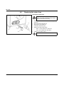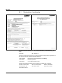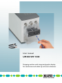
1
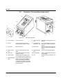
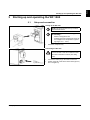
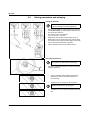
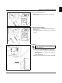
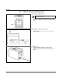
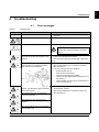
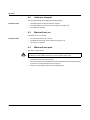
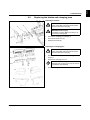
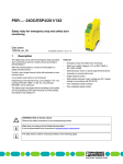
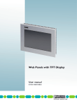
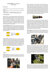
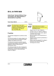
User manual
UM EN WF 1000
Stripping machine with integrated graphic display,
for conductors and cables up to 6 mm in diameter
User manual
Stripping machine with integrated graphic display, for conductors and
cables up to 6 mm in diameter
2012-04-30
Designation:
UM EN WF 1000
Revision:
02
Order No.:
—
This user manual is valid for:
Designation
Order No.
WF 1000
1212149
WF 1000 120V
1212258
PHOENIX CONTACT
103896_en_02
Please observe the following notes
User group of this manual
The use of products described in this manual is oriented exclusively to qualified electricians
or persons instructed by them, who are familiar with applicable standards and other regulations regarding electrical engineering and, in particular, the relevant safety concepts.
Explanation of symbols used and signal words
This is the safety alert symbol. It is used to alert you to potential personal injury
hazards. Obey all safety measures that follow this symbol to avoid possible injury or death.
There are three different categories of personal injury that are indicated with a
signal word.
DANGER
This indicates a hazardous situation which, if not avoided, will result in death or serious injury.
WARNING
This indicates a hazardous situation which, if not avoided, could
result in death or serious injury.
CAUTION
This indicates a hazardous situation which, if not avoided, could
result in minor or moderate injury.
This symbol together with the signal word NOTE and the accompanying text
alert the reader to a situation which may cause damage or malfunction to the
device, hardware/software, or surrounding property.
This symbol and the accompanying text provide the reader with additional information or refer to detailed sources of information.
How to contact us
Internet
Up-to-date information on Phoenix Contact products and our Terms and Conditions can be
found on the Internet at:
www.phoenixcontact.com
Make sure you always use the latest documentation.
It can be downloaded at:
www.phoenixcontact.net/catalog
Subsidiaries
If there are any problems that cannot be solved using the documentation, please contact
your Phoenix Contact subsidiary.
Subsidiary contact information is available at www.phoenixcontact.com.
Published by
PHOENIX CONTACT GmbH & Co. KG
Flachsmarktstraße 8
32825 Blomberg
GERMANY
Should you have any suggestions or recommendations for improvement of the contents and
layout of our manuals, please send your comments to:
[email protected]
PHOENIX CONTACT
Please observe the following notes
General terms and conditions of use for technical documentation
Phoenix Contact reserves the right to alter, correct, and/or improve the technical documentation and the products described in the technical documentation at its own discretion and
without giving prior notice, insofar as this is reasonable for the user. The same applies to any
technical changes that serve the purpose of technical progress.
The receipt of technical documentation (in particular user documentation) does not constitute any further duty on the part of Phoenix Contact to furnish information on modifications
to products and/or technical documentation. You are responsible to verify the suitability and
intended use of the products in your specific application, in particular with regard to observing the applicable standards and regulations. All information made available in the technical
data is supplied without any accompanying guarantee, whether expressly mentioned, implied or tacitly assumed.
In general, the provisions of the current standard Terms and Conditions of Phoenix Contact
apply exclusively, in particular as concerns any warranty liability.
This manual, including all illustrations contained herein, is copyright protected. Any
changes to the contents or the publication of extracts of this document is prohibited.
Phoenix Contact reserves the right to register its own intellectual property rights for the
product identifications of Phoenix Contact products that are used here. Registration of such
intellectual property rights by third parties is prohibited.
Other product identifications may be afforded legal protection, even where they may not be
indicated as such.
PHOENIX CONTACT
English
Table of contents
1
2
3
4
A
Basic information ....................................................................................................................1-1
1.1
Intended use....................................................................................................... 1-1
1.2
Workplaces ........................................................................................................ 1-2
1.3
For your safety.................................................................................................... 1-2
Description of the WF 1000 .....................................................................................................2-1
2.1
Supplied as standard.......................................................................................... 2-1
2.2
Overview of the operating components .............................................................. 2-2
Starting up and operating the WF 1000 ...................................................................................3-1
3.1
Setup and connection......................................................................................... 3-1
3.2
Setting parameters and stripping........................................................................ 3-2
3.3
Maintenance and shutting down......................................................................... 3-4
Troubleshooting ......................................................................................................................4-1
4.2
Cable not clamped ............................................................................................. 4-2
4.3
Blade will not cut.................................................................................................4-2
4.4
Blade will not open ............................................................................................. 4-2
4.5
Replacing the blades and clamping jaws............................................................4-3
4.6
Replacing the mains fuse ...................................................................................4-4
Technical appendix................................................................................................................. A-1
103896_en_02
A1
Ordering data .................................................................................................... A-1
A2
Technical data ................................................................................................... A-1
A3
Declaration of conformity................................................................................... A-2
PHOENIX CONTACT
i
WF 1000...
ii
PHOENIX CONTACT
103896_en_02
1
Basic information
For safe handling and trouble-free operation of the WF 1000, you must be familiar with and
observe the safety notes.
1.1
Intended use
WARNING: The WF 1000 is designed exclusively for stripping
The WF 1000 is designed exclusively for stripping single and multi-strand circular conductors in the cross-section range 0.08 - 6 mm² (28 - 10 AWG).
Very hard insulation will damage the stripping blades and must not be used.
Under no circumstances should solid metal parts or similar objects be inserted, as these
can damage the stripping blades and clamping jaws.
Unauthorized conversions that exceed the scope of modification, and changes to the
WF 1000 are not permitted for safety reasons.
NOTE: Correct usage includes observing all notes and complying with the predefined operating conditions.
WARNING: The WF 1000 may only be used
– as intended and
– when in safe and fault-free condition.
WARNING: All persons responsible for startup, operation, and maintenance of the
WF 1000 must be appropriately qualified and adhere strictly to this user manual.
Permitted operators
Only authorized and instructed operators may work with the WF 1000.
The operator is responsible for all other persons within the workspace.
The owner must make the user manual available to the operator and ensure that the operator has read and understood it.
WARNING: Only use original replacement parts from Phoenix Contact.
103896_en_02
PHOENIX CONTACT
1-1
English
Basic information
WF 1000...
1.2
Workplaces
NOTE: During operation and storage, avoid the following:
– humid or dusty places and
– locations exposed to high levels of heat, direct sunlight or low temperatures (operating range: 10°C to 40°C).
NOTE: Do not spill liquids on the WF 1000.
Do not expose the WF 1000 to strong vibrations or shocks.
1.3
For your safety
WARNING: The protective cover is fitted for the safety of the operator. Under no circumstances must it be modified, removed or bypassed by means of alterations.
WARNING: The WF 1000 must only be operated with the receptacle tray fitted and intact,
as this also acts as a protective cover.
Switch off the WF 1000 during breaks and when the device is not being used.
For reasons of safety, the WF 1000 automatically switches off when the protective cover is
removed.
WARNING: Disconnect the mains plug before opening the housing.
1-2
PHOENIX CONTACT
103896_en_02
2
Description of the WF 1000
2.1
Supplied as standard
1
4
2
3
Figure 2-1
1
2
3
4
Supplied as standard
Basic device WF 1000
Cable centering aid
Power cable
Receptacle tray (protective cover)
User manual
103896_en_02
PHOENIX CONTACT
2-1
English
Description of the WF 1000
WF 1000...
2.2
Overview of the operating components
1
13
2
12
11
9
3
10
7
4
5
6
8
Figure 2-2
Operating components
1
Carrier handle
Used for transport.
8
Cable centering
aid
2
Button
Used to reset the counter and
acknowledge messages or entries.
9
Receptacle tray
Acts as a protective cover and is
(protective cover) also used to catch the stripped insulation.
3
Motor axis
Manual operation
10 Start button
When the cable is inserted the start
button is pressed and stripping is
started.
4
Mains connection
Device connection for the power
cable.
11 Stripping length
knob
Used to set the stripping length.
5
Mains fuse
Fine fuses integrated in the mains
connection (2 pcs).
12 Diameter knob
Used to set the conductor diameter
(cutting depth).
6
Mains switch
Switches the power supply on/off.
13 LCD
The LCD lights up when switched on.
7
Removal length
knob
Used to set the removal length. If the
value is greater than the stripping
length, the remaining insulation is
completely removed from the cable.
If the value is smaller, the insulation is
partially removed.
2-2
PHOENIX CONTACT
Simplifies the stripping of thin conductors.
Displays settings, messages, and
errors.
103896_en_02
3
Starting up and operating the WF 1000
3.1
Setup and connection
Setting up the WF 1000
NOTE: The device must be set up on a level
and horizontal surface.
NOTE: During operation and storage, avoid
the following:
– humid or dusty places and
– locations exposed to high levels of heat, direct sunlight or low temperatures (operating range: 10°C ... 40°C).
•
Attach the receptacle tray.
Connecting the WF 1000
WARNING: The WF 1000 is available in two
versions for 230 V and 120 V. Make sure that
the mains connection is correct (see rating
plate).
•
•
103896_en_02
Connect the mains plug to the mains connection.
Switch on the WF 1000 via the mains switch (press I).
The LCD lights up.
PHOENIX CONTACT
3-1
English
Starting up and operating the WF 1000
WF 1000...
3.2
Setting parameters and stripping
Setting the diameter
NOTE: First, set the diameter of the conductor
to prevent damage to the stripping blades.
•
•
•
Determine the diameter of the conductor (in mm) and
add 0.4 mm leeway, to ensure that the WF 1000 does
not cut into the conductor.
For example: measured diameter
0.8 mm + 0.4 mm = 1.20 mm
Alternatively, the conductor cross section (mm²) or
AWG values can be converted into the corresponding
mm diameter value using the printed table. The leeway
value is already included in the calculation.
Set the calculated value via the middle knob (1).
1
Correcting the diameter
NOTE: The cut must stop 0.1 to 0.3 mm from
the conductor so that it does not damage it.
•
Check the cutting depth with a test cut and correct the
setting if necessary.
0.1 mm ... 0.3 mm
–
There is sufficient safety distance between the
blades and conductor and the insulation is removed cleanly.
–
The blades cut too deeply into the conductor.
NOTE: The blades may be damaged.
–
3-2
PHOENIX CONTACT
The blades do not cut deep enough into the insulation.
103896_en_02
Setting the stripping length (a)
a
•
2
Set the desired stripping length (mm) using the lefthand knob (2).
a
Setting the removal length (b)
•
3
Set the desired removal length (mm) using the righthand knob (3).
The remaining insulation can be partially or completely
removed.
b
b
Stripping
NOTE: Conductors inserted at an angle can result in malfunctions.
•
•
103896_en_02
Insert the conductor horizontally into the WF 1000.
– Conductor cross section up to ø 2.4 mm with cable centering aid
– Conductor cross section over ø 2.4 mm without
cable centering aid
Push the start button as close to the center as possible.
PHOENIX CONTACT
3-3
English
Starting up and operating the WF 1000
WF 1000...
3.3
Maintenance and shutting down
Emptying the receptacle tray
NOTE: Make sure that the receptacle tray does
not become too full.
•
Empty the receptacle tray regularly to prevent malfunctions.
Resetting the counter to zero (reset)
•
Press the button on the rear of the device to set the
counter to zero.
Shutting down
•
Switch off the WF 1000 via the mains switch (1)
(press 0) and disconnect the mains plug from the device (2).
2
1
3-4
PHOENIX CONTACT
103896_en_02
4
Troubleshooting
4.1
Error messages
Table 4-1
Troubleshooting
Display
Reason
Remedy
No display
No mains connection.
•
Check the mains fuse and replace if necessary (see
page 4-4).
Receptacle tray missing.
•
Attach the receptacle tray.
The button must be pressed.
•
Press the reset button.
WARNING: Risk of injury
The WF 1000 starts by moving from its initial
position.
The sensor for the start button does not re- •
spond properly when the machine is swit- •
ched on.
•
Disconnect the WF 1000 from the mains.
Remove the start button and clean it.
Blow down the metal pipe carefully with compressed
air.
The sensor for the front limit position is not
activated when the machine is started.
The contact is not established.
Switch the WF 1000 off.
Wait until the display goes out and then switch the
WF 1000 back on.
If the error message does not disappear:
– Switch the WF 1000 off.
– Remove the receptacle tray.
– Remove the clamping jaw cartridge.
– Check for foreign objects between the blade cover
and clamp (1).
– Check whether any of the screws on the blade cover have come loose (2).
•
•
•
2
1
The sensor for the rear turning point is ac- •
tivated, even though the device should be •
in the start position.
•
The maximum time for the stripping process was exceeded.
Check the settings on the display.
Switch the WF 1000 off.
Wait until the display goes out and then switch the
WF 1000 back on.
The maximum motor current was exceeded.
The receptacle tray was removed during
the operating cycle.
103896_en_02
PHOENIX CONTACT
4-1
English
Troubleshooting
WF 1000...
4.2
Cable not clamped
The cable slips through the clamping jaws during stripping.
Possible causes
–
–
–
The clamping jaws are dirty and must be cleaned.
The clamping jaws are worn and must be replaced (see page 4-3).
The cable is not suitable.
4.3
Blade will not cut
The blades do not cut correctly.
Possible causes
–
–
–
The correct parameters were not set.
The blades are blunt and must be replaced (see page 4-3).
The cable is not suitable.
4.4
Blade will not open
The blade no longer opens.
WARNING: Risk of injury
The blades are sharp. Make sure that you do not touch the cutting edge.
•
•
•
4-2
PHOENIX CONTACT
Carefully slide the blades back with a flat object.
The blades should snap back smoothly.
If the blades cannot be pushed back smoothly, dismantle the blades using the same
procedure as for blade replacement (see page 4-3).
Remove any remaining insulation from the stripping area.
103896_en_02
4.5
Replacing the blades and clamping jaws
Replacing the blades
WARNING: Risk of injury
3
Switch off the WF 1000 via the mains switch
and disconnect the mains plug.
2
1
WARNING: Risk of injury
The blades are sharp. Make sure that you do
not touch the cutting edge.
•
•
•
Remove the clamping jaw cartridge (1).
Remove the blade cover (2).
Replace the blades (3).
Replacing the clamping jaws
WARNING: Risk of injury
Switch off the WF 1000 via the mains switch
and disconnect the mains plug.
1
•
1a
•
Remove the covers (1b) from the clamping jaw cartridge (1).
Replace the clamping jaws (1a).
NOTE: When assembling, make sure that the
clamping jaws (1a) and covers (1b) are correctly positioned when installed.
1b
•
Fit the covers again.
!
1a
!
1b
103896_en_02
PHOENIX CONTACT
4-3
English
Troubleshooting
WF 1000...
4.6
Replacing the mains fuse
Replacing the mains fuse
WARNING: Risk of injury
Switch off the WF 1000 via the mains switch
and disconnect the mains plug.
•
2
•
•
•
•
4
1
3
•
Switch off the WF 1000 via the mains switch (1)
(press 0).
Disconnect the mains plug (2).
Remove the fuse holder (3).
Check the mains fuses (4).
Replace the faulty mains fuses:
– 230 V - 1.25 A mains fuse, slow-blow
– 115 V - 2.5 A mains fuse, slow-blow
Push the fuse holder back in
NOTE: The fuse holder must snap into place.
4-4
PHOENIX CONTACT
103896_en_02
English
A Technical appendix
A1
Ordering data
Stripping machine
Description
Type
Order No.
Pcs. / Pkt.
Stripping machine, 230 V version, for conductors and cables, solid and
stranded 0.08 - 6 mm² (maximum Ø 6 mm), with integrated graphic display
WF 1000
1212149
1
Stripping machine, 120 V version, for conductors and cables, solid and
stranded 0.08 - 6 mm² (maximum Ø 6 mm), with integrated graphic display
WF 1000 120V
1212258
1
Description
Type
Order No.
Pcs. / Pkt.
Stripping blade
WF 1000/SB
1212279
1 set
Clamping jaws
WF 1000/CJ
1212415
1 set
Start button
WF 1000/TR
1212416
1 set
Receptacle tray
WF 1000/COV
1212417
1 piece
Replacement parts
Cable centering aid
On request
230 V – 1.25 A mains fuse, slow-blow
–
–
2 pieces
115 V – 2.5 A mains fuse, slow-blow
–
–
2 pieces
A2
Technical data
Technical data
Mains connection
WF 1000
230 V/50 Hz
WF 1000 120V
120 V/60 Hz
Power consumption
160 VA
Processing cross section
0.08 mm² ... 6 mm²
Outside diameter, maximum
6 mm
Stripping length
2 mm ... 20 mm
Partial removal length
2 mm ... 20 mm
Insertion length + stripping length
15 mm + x
Stripping blade
V-shaped
Stripping time/cycle
0.2 s ... 0.3 s
Counter
6-digit LCD, can be reset
Dimensions (W x H x D)
141 x 221 x 363 mm
Weight of basic device
9.5 kg
103896_en_02
PHOENIX CONTACT
A-1
WF 1000...
A3
Declaration of conformity
PHOENIX CONTACT GmbH & Co. KG, Flachsmarktstraße 8, D-32825 Blomberg, Germany
WF 1000
WF 1000-120 V
The above-mentioned products are in conformity with the most important requirements of
the following directives and their amending directives.
2004/108/EC
EMC Directive (Electromagnetic Compatibility)
2006/42/EC
Machinery Directive
2006/95/EC
Low-Voltage Directive (LVD)
The following pertinent standards were consulted for evaluating the conformity:
EN ISO 12100-1:2003
EN ISO 12100-2:2003
EN ISO 13857:2008
EN 349:1993 + A1
EN 60204-1:2006
EN 61000-6-2:2005
EN 61000-6-3:2007
A-2
PHOENIX CONTACT
103896_en_02