1
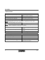
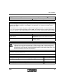
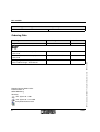
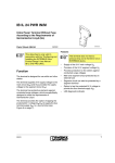
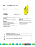
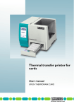
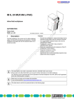
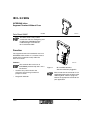
IB IL 24 SEG
INTERBUS Inline
Segment Terminal Without Fuse
Data Sheet 5566C
01/2001
5 5 6 6 3 0 0 1
This data sheet is only valid in
associaton with the “Configuring and
Installing the INTERBUS Inline
Product Range” User Manual
IB IL SYS PRO UM E.
Function
The segment terminal is intended for use in an
INTERBUS Inline station. It is used to create a
partial circuit (segment circuit) within the
main 24 V circuit.
Features
5 5 6 6 A 0 0 5
This terminal does not have an
INTERBUS protocol chip and is not a
bus device.
–
–
Creation of a partial circuit in the
main 24 V circuit using an external
jumper or switch
Diagnostic indicator
5566C
Figure 1
IB IL 24 SEG terminal
with the connector plugged in
Please note that the connector is not
supplied with the terminal. Refer to the
“Ordering Data” Table at page 6 to
choose the appropriate connector for
your application.
1
IB IL 24 SEG
Local Diagnostic Indicator
Des. Color Meaning
U S
US
S E G
Green 24 V voltage
(in segment circuit US)
Terminal Assignment
1
1 .1
The terminal points 1.1, 2.1, 1.2, and
2.2 are meant for the following
purposes only: measuring purposes,
and the connection of a switch or a
jumper on the segmentation level!
They must never be used to provide a
supply voltage.
2
1
2 .1
2 .2
Terminal Assignment
point
2 .3
1.1, 2.1
Segment voltage US
Connection of a switch or a jumper
in the segmentation level
1.2, 2.2
Main voltage UM
Connection of a switch or a jumper
in the segmentation level
1.3, 2.3
GND of the supply voltages
1.4, 2.4
FE connection
1
1 .2
2
2
1 .3
3
3
1 .4
4
4
2 .4
5 5 6 6 4 0 0 2
Figure 2
IB IL 24 SEG with the appropriate
connector
Function Identification
Black
2
5566C
IB IL 24 SEG
Internal Circuit Diagram
Connection Example
IN T E R B U S
IN T E R B U S
U L
U L
U S
S E G
1
+ 2
+ ( 2U
(U
+ 2
+ ( 2U
(U
+ 2
+ ( 2U
(U
4 V
4 V)
M
M )
2
1
1
2
2
3
3
4
4
4 V
4 V)
S
S )
4 V
4 V)
M
M )
5 5 6 6 A 0 0 4
Figure 4
Connection example of a switch
The switch can be used to set up a
switched segment circuit.
5 5 6 6 B 0 0 3
Figure 3
Internal wiring of the terminal
points
Key:
If this is not needed for your application, you
must jumper connections 1.1 and 1.2 or 2.1 and
2.2 to ensure that the segment circuit is supplied
from the main circuit.
LED
Capacitive connection to earth
ground (FE)
Other symbols are explained in the
IB IL SYS PRO UM E User
Manual.
5566C
3
IB IL 24 SEG
Technical Data
General Data
Housing dimensions (width x height x depth)
12.2 mm x 120 mm x 71.5 mm
(0.480 in. x 4.724 in. x 2.795 in.)
Weight
42 g (without connector)
Permissible temperature (operation)
-25°C to +55°C (-13°F to +131°F)
Permissible temperature (storage/transport)
-25°C to +85°C (-13°F to +185°F)
Permissible humidity (operation)
75%, on average, 85%, occasionally
Ranging from -25°C to +55°C (-13°F to +131°F). Appropriate measures against
increased humidity (> 85%) must be taken.
Permissible humidity (storage/transport)
75%, on average, 85%, occasionally
For a short period, slight condensation may appear on the housing if, for example, the
terminal is brought into a closed room from a vehicle.
Permissible air pressure (operation)
80 kPa to 106 kPa (up to 2000 m [6562 ft.] above
sea level)
Permissible air pressure (storage/transport)
70 kPa to 106 kPa (up to 3000 m [9843 ft.] above
sea level)
Degree of protection
IP 20 according to IEC 60529
Class of protection
Class 3 according to VDE 0106, IEC 60536
Power Consumption
Communications power UL
–
Current consumption UL
–
Power consumption UL
–
Main power UM
24 V DC (nominal value)
Nominal current consumption at UM
8.0 A (maximum permissible total current in the
voltage jumpers UM and US)
4
5566C
IB IL 24 SEG
Supply of the I/O through the bus terminal module and the power terminal (UM)
Connection method
Through potential routing
24 V I/O Supply (UM, US)
The main voltage UM is supplied through a bus terminal or a power terminal. At this segment
terminal, the segment voltage US is provided by the connection of a switch or a jumper on the
segmentation level.
No connections for a supply voltage are required on the segment terminal. The terminal points 1.1,
2.1, 1.2, 2.2 are meant for the following purposes only: measuring purposes, and the connection of
a switch or a jumper on the segmentation level!. They must never be used to provide supply voltage.
Safety Devices
Overload/short circuit in segment circuit
No
Surge voltage
Components in the power terminal or the bus
terminal module
Polarity reversal
Components in the power terminal or the bus
terminal module
Electrical Isolation
To provide electrical isolation between the logic level and the I/O area, it is necessary to
supply these areas of the bus terminal, or the bus terminal and a power terminal from
separate power supplies. Interconnection of power supply units in the 24 V range is not
allowed! Please pay attention to the GND-PE connections on the power supply units. (For
detailed information refer to the User Manual.)
Common potentials
24 V main power, 24 V segment voltage, and GND have the same potential. FE (functional earth
ground) is a separate potential area.
Separate system potentials consisting of bus terminal/power terminal and I/O terminal
- Test distance
- Test voltage
5 V supply incoming remote bus / 7.5 V supply (bus logic)
500 V AC, 50 Hz, 1 min.
5 V supply outgoing remote bus / 7.5 V supply (bus logic)
500 V AC, 50 Hz, 1 min.
7.5 V supply (bus logic) / 24 V supply (I/O)
500 V AC, 50 Hz, 1 min.
24 V supply (I/O) / functional earth ground
500 V AC, 50 Hz, 1 min.
5566C
5
IB IL 24 SEG
Error Messages to the Higher-Level Control or Computer System
None
Ordering Data
Meaning
Order Designation
Order No.
Segment terminal without fuse
IB IL 24 SEG
27 26 32 4
Connector (black, w/o color print)
pack of 10
IB IL SCN-PWR-IN
27 27 46 2
Connector (black, with color print)
pack of 10
IB IL SCN-PWR-IN-CP
27 27 63 7
“Configuring and Installing the INTERBUS
Inline Product Range“ User Manual
IB IL SYS PRO UM E
27 43 04 8
© Phoenix Contact 01/2001 Technical modifications reserved TNR 94 23 39 0
You need 1 connector for the 24 SEG terminal.
Phoenix Contact GmbH & Co.
Flachsmarktstr. 8
32825 Blomberg
Germany
+ 49 - (0) 52 35 - 3-00
+ 49 - (0) 52 35 - 3-4 12 00
www.phoenixcontact.com
6
5566C