1
Embedded Data Systems
HA7Net Ethernet to 1-Wire Bus Master
User’s Manual and Programmer’s Guide
Revised 08/09/2006
Embedded Data Systems, LLC.; 1446 Gilberts Creek Rd; Lawrenceburg, KY 40342; Phone/Fax 502-859-5490
1-37
Introduction................................................................................................................................................4
Intended Audience.................................................................................................................................4
HA7Net Hardware Overview......................................................................................................................5
Form Factor............................................................................................................................................5
Power Supply Requirements..................................................................................................................5
Internal Clock.........................................................................................................................................5
Internal Battery.......................................................................................................................................5
Ethernet Interface...................................................................................................................................5
1-Wire Interface......................................................................................................................................6
Configuration / Setup.................................................................................................................................7
Administrator Password.........................................................................................................................7
User Password.......................................................................................................................................7
TCP/IP Settings......................................................................................................................................7
SNTP......................................................................................................................................................9
Miscellaneous.........................................................................................................................................9
Update....................................................................................................................................................9
Reboot..................................................................................................................................................10
Factory Reset.......................................................................................................................................11
1-Wire Technology Overview...................................................................................................................12
Device Selection...................................................................................................................................12
Device Interaction.................................................................................................................................12
Typical 1-Wire Communication Process..............................................................................................13
Family Codes.......................................................................................................................................14
HA7Net Ethernet Communication Interfaces...........................................................................................15
Telnet Interface....................................................................................................................................15
Multicast Listener.................................................................................................................................15
Packet Format..................................................................................................................................15
HTTP Interface.....................................................................................................................................16
Data Table........................................................................................................................................17
Exception Table................................................................................................................................17
Statistics Table.................................................................................................................................18
Concurrency Management...................................................................................................................18
HTTP Interface API Reference................................................................................................................20
High Level Commands.........................................................................................................................20
High Level Command List....................................................................................................................21
Read Analog Probe..........................................................................................................................21
Read Temperature...........................................................................................................................21
Read DS18B20.................................................................................................................................22
Set Display........................................................................................................................................22
Low Level Commands..........................................................................................................................23
Low Level Command List.....................................................................................................................23
Search ROM Command...................................................................................................................24
Address Device Command...............................................................................................................25
Match ROM Command.....................................................................................................................26
Reset Command...............................................................................................................................27
Power Down Bus Command............................................................................................................28
Write Block Command......................................................................................................................29
Read Bit Command..........................................................................................................................31
Read File Records Command..........................................................................................................34
Write File Record Command............................................................................................................35
Get Lock Command..........................................................................................................................36
Embedded Data Systems, LLC.; 1446 Gilberts Creek Rd; Lawrenceburg, KY 40342; Phone/Fax 502-859-5490
2-37
Release Lock Command..................................................................................................................37
Embedded Data Systems, LLC.; 1446 Gilberts Creek Rd; Lawrenceburg, KY 40342; Phone/Fax 502-859-5490
3-37
Introduction
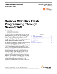
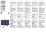
Welcome to the HA7Net. A product that is designed to simplify the integration of distributed 1-Wire /
iButton networks into your application or system. By acting as an Ethernet to 1-Wire bridge, the
HA7Net serves as an efficient tool that can be used to overcome a variety of challenges related to the
successful implementation of 1-Wire MicroLans.
1-Wire Bus
Client PC
HA7Net
Internet
10/100 Base Ethernet
LAN
Any Client PC shown here can talk to any 1-Wire
device shown here using standard Ethernet /
Internet technologies as the communications
backbone .
HA7Net
1-Wire Bus
Client PC
HA7Net
1-Wire Bus
Figure 1
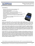
The HA7Net allows you to effectively use industry standard Ethernet networking products to build out
the backbone of your 1-Wire sensor system, providing several important benefits: First, the individual
1-Wire MicroLans can be kept to a smaller physical size, thereby improving reliability and decreasing
installation costs. Second, since the HA7Net communicates via TCP/IP over standard Ethernet, you
can take advantage of existing corporate LANs, the Internet, and in-house MIS expertise for building
out your sensor network, as shown in figure 1. Another advantage is the number of readily available
libraries and developer tools that can be used to communicate with the HA7Net. These are widely
available for common development platforms.
Intended Audience
This document is intended for the developer / integrator charged with the task of designing the 1-Wire
sensor MicroLans and writing the software that will interface with the HA7Net
Embedded Data Systems, LLC.; 1446 Gilberts Creek Rd; Lawrenceburg, KY 40342; Phone/Fax 502-859-5490
4-37
HA7Net Hardware Overview
Form Factor
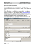
The HA7Net is available in both panel mount and DIN rail form factors. The
panel mount version suitable for desktop or wall mounting while the DIN rail
version is compatible with industry standard DIN-35 mounting rails typically
found in industrial environments.
Power Supply Requirements
The HA7Net is fitted with a 2.5mm power jack suitable for connection to any 6-12 Volt DC power
supply having a F2 (2.5mmID x 5.5mmOD) female type plug wired for positive polarity on the center
conductor. The power supply should capable of delivering 500mA.
Internal Clock
The HA7Net is equipped with an internal battery backed DS2417 real-time clock, which itself is a 1Wire device connected to the primary 1-Wire bus. The clock is used for such things as managing
security certificate lifetimes as related to the SSL portion of the internal http server, and is also used as
a reference for time stamping each result page returned from the HA7Net. Since the clock is
connected to the primary 1-Wire bus, it can be used in simple diagnostics to determine the correct
operation of the HA7Net. This also means that it can be completely accessed by the integrator. The
DS2417 clock has a specified accuracy of +/- 2 minutes per month. For increased long-term accuracy,
the HA7Net can be configured to periodically synchronize it with a SNTP time server.
Internal Battery
The HA7Net is equipped with a user replaceable Lithium CR2032 coin cell battery. This battery serves
to power the internal real-time clock such that the HA7Net’s clock settings are not lost during power
failures, etc. Note that all other configuration settings (network settings, user names, etc.) are stored in
non-volatile memory that is not dependant on the battery. In other words, removing the battery will
only affect the clock…it will not erase other configuration settings.
Ethernet Interface
The HA7Net is equipped with a standard 8-Wire RJ-45 Ethernet jack that meets the ISO 8877
requirements for 10/100BASE-T. Both half and full duplex modes of operation are supported on the
Ethernet interface. If you are connecting to a hub or switch, a straight through cable should be used. If
connecting directly to a PC, then a crossover cable should be used.
Embedded Data Systems, LLC.; 1446 Gilberts Creek Rd; Lawrenceburg, KY 40342; Phone/Fax 502-859-5490
5-37
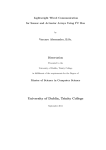
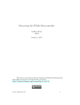
1-Wire Interface
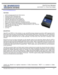
For ease of use, the HA7Net is equipped with three 1-Wire ports which are wired in parallel. Each port
is a standard 6-Wire RJ11 (RJ12) jack, pinned for use with 1-Wire devices as follows:
RJ11 Jack
Pin 6
Pin 5
Pin 4
Pin 3
Pin 2
Pin 1
Pin 1: No Connection
Pin 2: No Connection
Pin 3: 1-Wire Signal / Data
Pin 4: Ground
Pin 5: No Connection
Pin 6: User Selectable Vdd
Regarding pin 6 (Vdd)…inside the HA7Net are three jumpers located next to the
RJ11 jacks. By manipulating these jumpers, pin 6 can be configured for any of
three states:
•
•
•
+5 Volt DC power supplied, up to 200mA. This might be useful if you want to
provide external power to sensors such as the DS18x20.
GND- Pin will be held to the common 1-Wire GND level
Floating- The pin will be physically disconnected inside the HA7Net. This might be useful if you
have other devices on the bus that need to control this line.
The default configuration when shipped from us is Floating / No Connection. Depending on the exact
type of sensors you are connecting to the HA7Net, you may want to supply power (i.e to operate a
DS18x20 in powered mode), or an extra ground (i.e. to operate a DS18x20 in parasitic power mode, in
which case the Vdd pin must be connected to ground). For most iButtons, the Floating / No
Connection configuration is just fine.
The HA7Net supports up to 2000 feet of cabling and 100 1-Wire devices on a CAT-5 twisted pair net,
and automatically provides smart strong-pull-up for sensors. ESD protection to more than 27kV
(IEC801-2 Reference Model) is provided on the 1-Wire bus.
Embedded Data Systems, LLC.; 1446 Gilberts Creek Rd; Lawrenceburg, KY 40342; Phone/Fax 502-859-5490
6-37
Configuration / Setup
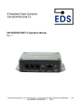
The HA7Net is generally usable right out of the box, but in most cases you will want to configure
certain options, as discussed here. Configuration is performed by using a web browser to connect to
the HA7Net, whereby the following page should be presented:
The left hand side of this page contains a menu of the various configuration options available. To enter
into any of the configuration screens, you must be able to supply the current administration password.
Administrator Password
The default administrator username / password combination is as follows (please note that these are
case sensitive):
User: admin (can not be changed)
Password: eds
We highly recommend changing the default
password.
The administrative password is required in
order to access any of the HA7Net
configuration screens, as well as the telnet
interface. Additionally, the administrative
password can be used in lieu of the ‘User’
password to gain access to the 1-Wire bus.
User Password
If set, this password will be required in order to access any of the 1-Wire Forms or API. By default, this
password is not set. This password can be used to provide access control to your 1-Wire bus. The
username associated with this password is ‘user’.
TCP/IP Settings
The HA7Net ships with the following default TCP/IP configuration: First, the device will attempt to
obtain an IP addresses from a local DHCP server. If that fails, then the HA7Net will default to a static
IP address of 192.168.0.250, with a netmask of 255.255.255.0. Using the TCP/IP configuration
screen, the following parameters can be specified:
Embedded Data Systems, LLC.; 1446 Gilberts Creek Rd; Lawrenceburg, KY 40342; Phone/Fax 502-859-5490
7-37
•
•
•
•
•
•
•
•
Obtain IP Configuration via DHCP
This instructs the HA7Net to load all TCP/IP settings from a local DHCP server.
Use Static on DHCP Failure:
By enabling this option, the HA7Net will ‘fall back’ to its statically configured parameters if it is
unable to negotiate a DHCP lease. If this is not enabled, then the HA7Net will continuously
attempt to locate a DHCP server.
Static IP Address
Network Mask
Default Route (Gateway)
Primary DNS server (optional)
Secondary DNS server (optional)
HTTP Port
Defines which port number the HA7Net’s internal web server will listen on.
Note that if the device successfully configures itself via DHCP, then you will either have to consult your
DHCP server logs, or take advantage of the HA7Net’s multicast listener in order to discover the
HA7Net’s IP address.
Embedded Data Systems, LLC.; 1446 Gilberts Creek Rd; Lawrenceburg, KY 40342; Phone/Fax 502-859-5490
8-37
Date/Time
This form can be used to configure the time and date stored in the HA7Net’s real-time clock. We
recommend setting this to GMT, but this is
not a requirement and you may want to
use another time zone depending on your
application. Pressing the “Guess” button
will populate the fields by converting your
PC’s time to GMT. Note that the HA7Net
can automatically keep its clock
synchronized to a network time server, by
configuring the SNTP settings.
SNTP
SNTP is a simple network time protocol,
which is supported by many commonly available
servers. By enabling the ‘Sync Time using SNTP’
option and configuring at least one SNTP server,
the HA7Net will periodically synchronize its internal
clock to that of the SNTP server. Note that using
this option will force the HA7Net’s clock to GMT.
For more information on SNTP, please consult your
favorite Internet search engine.
Miscellaneous
The miscellaneous tab is used to configure the following parameters:
•
Device Name:
This allows you to assign a friendly name to your HA7Net. This name will be reported during
the multicast discovery process.
•
Lock idle timeout (seconds):
This timeout discusses the amount of
time that a 1-Wire bus lock can remain
idle before the HA7Net forcibly releases
it. For a complete discussion of 1-Wire
bus locking, see the section entitled
“Concurrency Management”, later in this
document.
Update
The update form is used to flash the HA7Net with new versions of its firmware, which we make
available from time to time on our technical support website at the following URL:
http://talk1wire.com/?q=node/60
After unzipping the firmware file downloaded from our website, you should be left with a .bin file named
something similar to “HA7_1.0.0.14.bin”. It is this .bin file that you will need to upload to the HA7Net
using the Update form found on the configuration menu.
Embedded Data Systems, LLC.; 1446 Gilberts Creek Rd; Lawrenceburg, KY 40342; Phone/Fax 502-859-5490
9-37
After the upload process, the HA7Net will perform several validity tests on the new firmware file. If any
of the tests fail, then the HA7Net will not allow you to commit the firmware to flash memory. If all of the
tests pass, then the HA7Net will prompt for final confirmation that you want to write the new firmware to
flash memory, as shown below:
To commit the new firmware to flash memory, click on the ‘Flash Device’ button. Note that this process
will take 2-3 minutes, and the HA7Net will automatically restart after the process is complete. Unless
otherwise noted in the firmware release notes, your existing configuration will be preserved during the
update. Disconnecting power during this process will result in corrupted firmware. If this happens,
please contact technical support for a recovery process.
Reboot
Some configuration settings require restarting the HA7Net before they will take effect. This form allows
you to reboot the HA7Net from remote.
Embedded Data Systems, LLC.; 1446 Gilberts Creek Rd; Lawrenceburg, KY 40342; Phone/Fax 502-859-5490
10-37
Factory Reset
Resetting the HA7Net to factory defaults will set the following configuration values:
•
IP Address: First tries DHCP, if no DHCP server found, then defaults to 192.168.0.250
•
Admin User: admin
•
Admin Password: eds
•
Http Port: 80
•
Https Port: 443
The reset procedure is performed as follows:
Start by unplugging the HA7Net, and then remove the top cover. Inside, you will see two metallic pads
near the center of the PCB labeled 'Factory Reset'.
Use an appropriate tool (tweezers, paper clip, etc.) to short these two pads together. While shorting
these two contacts, power-up the HA7Net.
** Keep the two contacts shorted together until you see the green and red LEDs on the front of the HA7Net begin to
flash alternately. **
At this point you have triggered the HA7Net to perform a reset, and you can remove the short.
Overall, the reset will take one to two minutes to complete, as the HA7Net will generate a new SSL
certificate during the process...a very computationally intensive task. After the reset is complete, the
LEDs will return to normal operation, and the HA7Net should operate using the default configuration
values given above.
Embedded Data Systems, LLC.; 1446 Gilberts Creek Rd; Lawrenceburg, KY 40342; Phone/Fax 502-859-5490
11-37
1-Wire Technology Overview
1-Wire is a technology created by Dallas Semiconductor which is centered around a data bus that
implements a simple signaling scheme used to perform two-way communications between a single
master and multiple peripheral devices over a single connection. A powerful feature common to all 1Wire bus devices is that each and every device, whether in a chip or an iButton form, has a factorylasered serial number that will never be repeated in any other device. That is to say, every device is
unique. This allows any single device to be individually selected from among many that can be
connected to the same bus wire. Because one, two, or even dozens of 1-Wire devices can share a
single wire for communications, a binary searching algorithm is used to find each device in turn. Once
each device serial number is known, any device can be uniquely selected for communication using that
serial number to address it.
Device Selection
The first part of any 1-Wire communication generally involves the bus master issuing a “reset” which
synchronizes the entire bus. A slave device is then selected for subsequent communications. This can
be done by selecting all slaves, or by selecting a specific slave (using the serial number of the device).
These commands are referred to collectively as
“network” or ROM (Read-Only-Memory) commands, and are implemented on the HA7Net in the form
of the ‘Search’, ‘Address’, and ‘Match’ commands. Once a specific device has been selected, all other
devices drop out and ignore subsequent communications until the next reset is issued.
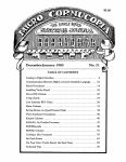
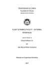
Because each 1-Wire device type performs different functions and serves a different purpose, each
has a unique protocol once it has been selected. Even though each device type may have different
protocols and features, they all have the same selection process and follow the command flow as seen
in the following figure:
Reset 1-Wire Bus
Select 1-Wire
Device(s)
Perform Device
Specific Operation
Device Interaction
Once a device is isolated for bus communication (selected) the master can issue device-specific
commands to it, send data to it, or read data from it. This is generally accomplished using
combinations of the following HA7Net commands: ‘Write Block’, ‘Write Bit’, ‘Read Bit’, ‘Read Pages’,
‘Read Records’, and ‘Write Record’. Since each 1-Wire device type performs different functions, they
each implement their own protocol for interacting with it after the selection process. The HA7Net
commands above will allow you to effectively interact with any 1-Wire device manufactured, present or
future, regardless of its protocol.
Embedded Data Systems, LLC.; 1446 Gilberts Creek Rd; Lawrenceburg, KY 40342; Phone/Fax 502-859-5490
12-37
Typical 1-Wire Communication Process
Putting this altogether, communications with devices on a 1-Wire bus typically follow a flow similar to
the following:
Yes
Acquire Exclusive use of 1Wire Bus
Discover / Select 1-Wire
Device
Perform Device Specific
Interactions
Perform
Another
Action?
No
Release Exclusive
use of 1-Wire Bus
Embedded Data Systems, LLC.; 1446 Gilberts Creek Rd; Lawrenceburg, KY 40342; Phone/Fax 502-859-5490
13-37
Family Codes
An integral part of the unique serial number in each 1-Wire device is an 8-bit family code. This code is
specific to the device’s model type. Because each device model performs different functions, this code
can be used to select the protocol that will be used to control or interrogate it. The following table
provides a partial mapping of family codes to Dallas Semiconductor part numbers:
Family
Code
Part Number
()iButton Package
Description
(Memory size in bits unless specified)
01 (hex)
(DS1990A)*, DS2401
1-Wire net address (serial number) only
04
(DS1994), DS2404
4k NV RAM memory and clock, timer, alarms
05
DS2405
Single addressable switch
06
(DS1993)
4k NV RAM memory
08
(DS1992)
1k NV RAM memory
09
(DS1982), DS2502
1k EPROM memory
0A
(DS1995)
16k NV RAM memory
0B
(DS1985), DS2505
16k EPROM memory
0C
(DS1996), (DS1996x2),
(DS1996x4)
64k to 256k NV RAM memory
0F
(DS1986), DS2506
64k EPROM memory
10
(DS1920), DS1820,
DS18S20
Temperature with alarm trips
12
DS2406, DS2407
1k EPROM memory, two channel addressable switch
14
(DS1971), DS2430A
256-bit EEPROM memory and 64-bit OTP register
18
(DS1963S)
4k NV RAM memory and SHA-1 engine
1A
(DS1963L)
4k NV RAM memory with write cycle counters
1D
DS2423
4k NV RAM memory with external counters
1F
DS2409
2 channel addressable coupler for sub-netting
20
DS2450
4 channel A/D
21
(DS1921), (DS1921H),
(DS1921Z)
Thermochron™ temperature logger
22
DS1822
Econotemperature
23
(DS1973), DS2433
4k EEPROM memory
24
(DS1904), DS2415
Real-time clock (RTC)
26
DS2438
Temperature, A/D
27
DS2417
RTC with interrupt
28
DS18B20
Adjustable resolution temperature
33
(DS1961S), DS2432
1k EEPROM memory with SHA-1 engine
Embedded Data Systems, LLC.; 1446 Gilberts Creek Rd; Lawrenceburg, KY 40342; Phone/Fax 502-859-5490
14-37
HA7Net Ethernet Communication Interfaces
The HA7Net provides 3 network services accessible via TCP/IP:
1. HTTP Server -The primary means of interfacing with the HA7Net is via the HTTP protocol,
available by default on port 80 (non-SSL) and port 443 (SSL).
2. Telnet Server -A debugging facility is also provided via a Telnet interface located on the
standard telnet port (23).
3. Multicast Listener –A multicast listener is integrated into the HA7Net for ease of device
discovery in dynamically configured networks. When the HA7Net hears the appropriate
multicast packet, it will respond with a directed UDP packet containing information about how to
contact the HA7Net.
Telnet Interface
As an aid in both troubleshooting and the initial integration process, the HA7Net offers a telnet server
that can be used to monitor what is happening internal to the device. This interface is available on the
standard telnet port (23), and is secured by the HA7Net’s administrative level password.
The telnet interface provides access to messages and logging from each of the individual subsystems
in the HA7Net, currently:
•
Http Server
•
Debug / Logging Facility
•
1-Wire Network Activity
•
Telnet Server
•
Clock Maintenance
The messages are formatted in the standard Unix syslog format, and each subsystem can be
individually configured for the desired logging level ranging from practically none (Emergency) to nearly
everything (Debug).
Multicast Listener
In order to provide a mechanism for discovering HA7Nets on a dynamically addressed (i.e. DHCP)
networks, the HA7Net has an integrated multicast listener that will respond to properly formatted
multicast packets with a directed UDP packet. This allows the client to discover all of the HA7Nets
within reach of a single multicast packet.
Packet Format
The multicast packet transmitted from the client to the HA7Net should be constructed as follows:
Char
signature[2]; -> ”HA”
WORD16
command;
-> 0x0001
For Example:
0x48410001-> “HA\000\001”
This packet should be transmitted to group (IP): 224.1.2.3, port 4567.
Embedded Data Systems, LLC.; 1446 Gilberts Creek Rd; Lawrenceburg, KY 40342; Phone/Fax 502-859-5490
15-37
When this packet is detected, the HA7Net will respond with a UDP packet directed back to the same IP
address and originating port of the client that transmitted the multicast. The format of the response
packet is as follows:
char
WORD16
WORD16
WORD16
char
char
signature[2];
command;
port;
sslport;
serial_num[12]
dev_name[64]
->
->
->
->
->
->
“HA”
0x8001
Non-SSL http port (80)
SSL http port (443)
HA7Net serial (MAC)
HA7Net device name
Note that the serial_num and dev_name fields will not be null terminated if the data occupies the entire
allocation, otherwise they will be null terminated. The client should be able to locate each of the
HA7Nets by querying the client’s underlying TCP/IP stack for the remote IP information of the received
UDP packet. As shown above, the response packet will include the port numbers of both the non-SSL
and SSL http servers. These servers default to being located on ports 80 and 443 respectively, but
can be re-configured by the integrator. If either of the http servers are disabled, then the port number
will be returned as 0.
The following is an excerpt from a Visual Basic code sample for transmitting the multicast packet and
receiving the response:
Private Sub Form_Load()
Dim sckHndl As Long
Winsock1.Protocol = sckUDPProtocol
sckHndl = Winsock1.SocketHandle
setsockopt sckHndl, SOL_SOCKET, SO_BROADCAST, 1, 1
With Winsock1
.RemotePort = 4567
.RemoteHost = "224.1.2.3"
.SendData "HA" & Chr$(0) & Chr$(1)
End With
End Sub
Private Sub Winsock1_DataArrival(ByVal bytesTotal As Long)
Dim responseData As String
Winsock1.GetData responseData, vbString, bytesTotal
Debug.Print responseData & Winsock1.RemoteHostIP & Winsock1.RemotePort
End Sub
HTTP Interface
Primary communication with the HA7Net is via the http protocol. The actual data is exchanged in the
form of html documents which have been designed to accommodate both human readability and 100%
reliable machine parsing. This is accomplished through the use of unique, predictably named form
fields that can be automatically parsed by Document Object Model (DOM) parsers, or easily digested
via regular expressions on lighter weight platforms. Data is passed to the HA7Net in the form of
parameters placed in the URL.
Since the result pages are human readable, both proof of concept and integration time is reduced as
you can effectively interact with the HA7Net using a standard web browser.
For example, to discover all of the devices that are connected to the 1-Wire bus, the client would
request the following URL from the HA7Net: http://HA7.net/1Wire/Search.html. The HA7Net will then
respond with an html document that renders similar to the following in a standard web browser:
Embedded Data Systems, LLC.; 1446 Gilberts Creek Rd; Lawrenceburg, KY 40342; Phone/Fax 502-859-5490
16-37
You can see that the serial number of each 1-Wire device appears in a form field. Taking a look at the
source of this html document, you can see how the data is also easily machine parseable via regular
expressions, or higher level DOM or SAX parsers.
Each html response document is typically divided into three primary sections that are organized into
html tables. The three sections are used to discuss:
•
The data portion of the response.
•
Exceptions that may occur during the request.
•
Statistical information about the request.
Data Table
The following is the section of the html document shown above that discusses the serial numbers of
the 1-Wire devices:
<table name="Addresses" id="Addresses">
<tr>
<td>
<input CLASS="HA7Value" NAME="Address_0" ID="ADDRESS_0" TYPE="text"
VALUE="A100000000E22820">
</td>
</tr>
<tr>
<td>
<input CLASS="HA7Value" NAME="Address_1" ID="ADDRESS_1" TYPE="text"
VALUE="280000003042C210">
</td>
</tr>
<tr>
<td>
<input CLASS="HA7Value" NAME="Address_2" ID="ADDRESS_2" TYPE="text"
From this, you can see that all of the 1-Wire addresses are contained in a table named “Addresses”,
and each of the individual addresses are contained in a text field named “Address_x”, where x is a 0
based sequential number. This can data can be parsed automatically by DOM parsers, or by simply by
using a regular expression similar to the following:
's/.*<INPUT.*NAME="Address_\(.*\)".*VALUE="\(.*\)".*./\2/p'
In fact, the following is a sample Linux command line that can be used to communicate to an HA7Net
which will print the address of all of the 1-Wire devices connected to the HA7Net to stdout:
curl -q "http://ha7.net/1Wire/Search.html" 2>/dev/null | sed --silent -e 's/.*<INPUT.*NAME="Address_\(.*\)".*VALUE="\(.*\)".*./\2/p'
Exception Table
The following is the section of the html document shown above that discusses any exceptions that may
have occurred during the request:
Embedded Data Systems, LLC.; 1446 Gilberts Creek Rd; Lawrenceburg, KY 40342; Phone/Fax 502-859-5490
17-37
<table name="Exceptions" ID="Exceptions">
<tr>
<td>
<input CLASS="HA7Value" NAME="Exception_Code_0" ID="Exception_Code_0" TYPE="hidden" VALUE="0">
</td>
<td>
<input CLASS="HA7Value" NAME="Exception_String_0" ID="Exception_String_0" TYPE="hidden" VALUE="None">
</td>
</tr>
</table>
In this example, there where no exceptions encountered as indicated by the form field named
“Exception_Code_0” having its value equal to “0”. When this is the case, the exception fields are type
hidden to prevent rendering in the web browser. If there had been an actual exception the fields would
be type text. It is recommended that client applications always check for exceptions and handle them
as appropriate. A complete listing of exceptions and possible causes are discussed later in this
document.
Statistics Table
The following is the section of the html document show above that discusses statistics regarding the
specific request:
<table name="Statistics" ID="Statistics">
<tr>
<td>
<input TYPE="HIDDEN" NAME="Completed_0" VALUE="101446">
</td>
</tr>
</table>
Shown here is the only statistical data currently implemented, which is the timestamp when the html
document was created on the HA7Net. The value represents the number of seconds since January 1,
1970, and is stored in the field named “Completed_0”. This timestamp can be used to determine the
when the request was completed regardless of any latency between the client and the HA7Net. This
can be useful when calculating the rate at which a piece of data is changing across multiple requests.
Concurrency Management
The physical layer of the 1-Wire MicroLan is designed such that only one data request or operation can
be made on the 1-Wire bus at a time. It is also common for a single logical transaction to span multiple
physical 1-Wire requests. Given this modal nature of the 1-Wire bus, and the multi-user nature of the
http interface, it is necessary for the HA7Net to provide a means of concurrency and bus contention
management. Concurrency management is provided on the HA7Net via a traditional locking
mechanism wherein a client will request a lock on the 1-Wire bus and no other clients will be allowed
access to the bus until the lock is either explicitly released by the client, or expires due to inactivity.
The default maximum idle lifetime of the locks can be configured per HA7Net, and has a default value
of 60 seconds.
The general process for interacting with the HA7Net in a multi-user environment looks like this:
•
Client requests lock of the 1-Wire bus
o http : / / HA 7 . Net / 1 - Wire /GetLock . h tml
•
HA7Net responds with a new LockId when the bus is available
•
Client performs transactions while referencing the LockID
o http : / / HA 7 . Net / 1 - Wire / Temperature . h tml ? Lock ID = xxxxxxx&Address =1 2 3 4 5 6 7 8 1 2 3 4 5 6 7 8
o http : / / HA 7 . Net / 1 - Wire / Sea rch . h tml ? Lock ID = xxxxxx&FamilyCode=10 &Condi t i ona l = T rue
•
Client releases previously acquired lock
o http : / / HA 7 . Net / 1 - Wire / Re leaseLock . h tml ? Lock ID = xxxxxxx
For the duration of the lock, only clients that reference the currently valid lock-id will be allowed to
access the 1-Wire bus. All other requests will block until the bus is available.
In summary, all 1-Wire activities are handled atomically within the HA7Net so all requests made that do
not reference a LockID are guaranteed to have uninterrupted access to the 1-Wire bus for the duration
Embedded Data Systems, LLC.; 1446 Gilberts Creek Rd; Lawrenceburg, KY 40342; Phone/Fax 502-859-5490
18-37
of that particular request. By requesting and referencing an explicit lock, a client can guarantee itself
uninterrupted access to the 1-Wire bus across multiple requests.
Embedded Data Systems, LLC.; 1446 Gilberts Creek Rd; Lawrenceburg, KY 40342; Phone/Fax 502-859-5490
19-37
HTTP Interface API Reference
In terms of interacting with the 1-Wire bus, we divide the HA7Net command set into two categories.
The first is a high-level command set in which the HA7Net provides high level functionality for working
with various 1-Wire devices. This saves the developer from having the learn and implement the low
level details of communicating to each different type of 1-Wire device. For example you can simply ask
the HA7Net to read the current temperature from a DS18S20. The second category is a low level
command set. By using the low level commands, you can take complete manual control of the 1-Wire
bus down to the level of reading and writing individual data bits.
High Level Commands
The high level commands are designed to simplify the process of interacting with specific 1-Wire
devices. Many 1-Wire devices require a number of communications between the bus master and the
slave in order to accomplish a single task. For example, to read the current temperature from a
DS18B20 temperature sensor, the following low-level steps are typically required:
•
Address the DS18B20
•
Configure the Operating Resolution of the sensor
•
Reset the 1-Wire bus and re-address the sensor.
•
Tell the sensor to perform a temperature conversion
•
Wait for the conversion to complete
•
Reset the 1-Wire bus and re-address the sensor.
•
Read the scratchpad memory of the DS18B20
•
Decipher the temperature reading from the data in the scratchpad.
Instead of executing these low-level steps, you can simply ask for the current temperature of an entire
list of DS18B20s using the HA7Net’s high-level ReadDS18B20 command. The HA7Net will execute
the steps above for each sensor on your list, and then return you a single html page containing the
temperature of every sensor expressed in degrees Celsius.
In addition to reducing the required learning curve and implementation time, this functionality also
dramatically decreases the time required to complete certain operations, and allows your application to
scale much better than non-intelligent network bus masters. Traditionally, 1-Wire bus masters have
been connected directly to serial ports on PCs or PLCs where the latency between the application and
the bus master is negligible. Now that your bus master may be located anywhere in the world away
from your application, the latency introduced by the underlying communication infrastructure becomes
significant. Even with typical Internet ping times of 100-200 mS, you can see that the DS18B20
example above would have between 1 to 2 seconds of additional overhead added to the reading of
each sensor. Multiply this by 100 or more temperature sensors, or consider using higher latency
Internet connections such as satellite, and it quickly becomes obvious how lower-level solutions will fail
to scale up.
Embedded Data Systems, LLC.; 1446 Gilberts Creek Rd; Lawrenceburg, KY 40342; Phone/Fax 502-859-5490
20-37
High Level Command List
The following is an overview of each high-level http request that can be made to the HA7Net. Detailed
reference on each command can be found on the pages that follow.
Read Analog Probe
URL: /1Wire/ReadAnalogProbe.html?Address_Array=Address1,Address2,Address3,…
Example: http://ha7.net/1Wire/ReadAnalogProbe.html?Address_Array=DE0000001B137312
The ReadAnalogProbe function allows you to easily read the current value from a mixed list of
Embedded Data Systems’ complex 1-Wire sensors. Currently supported devices include:
•
•
BAR2001S Barometric Pressure / Temperature Sensor
HMP2001S Humidity / Temperature Sensor
When calling the URL, you provide a list of the sensors you want to be read. The HA7Net will
sequentially read each sensor, and then return a single html page containing a list of the sensors, the
sensor type, the engineering value of the sensor reading, the units, the address of any associated
temperature sensor, and the temperature of each sensor expressed in degrees Celsius, as shown
below. Any errors encountered while reading the sensor will be listed in the status field.
Read Temperature
URL: /1Wire/ReadTemperature.html?Address_Array=Address1,Address2,Address3,…
Example: http://ha7.net/1Wire/ReadTemperature.html?Address_Array=9D00080027AF4A10,73000000B0E22E28
The ReadTemperature function allows you to read the current temperature from a list of mixed 1-Wire
device types. Currently supported devices include:
•
DS18B20
•
DS18S20
•
DS1920
•
DS2438
When calling the URL, you provide a list of the sensors you want to be read. Any sensors that can be
operated at multiple resolutions (e.g. DS18B20) will be read using their current configurations. The
HA7Net will sequentially read each sensor, and then return a single html page containing a list of the
sensors, the temperature of each sensor expressed in degrees Celsius, and the current operating
resolution of the sensor, as shown below. If you want to control the resolution of the DS18B20, see the
ReadDS18B20 function, below.
Embedded Data Systems, LLC.; 1446 Gilberts Creek Rd; Lawrenceburg, KY 40342; Phone/Fax 502-859-5490
21-37
Read DS18B20
URL: /1Wire/ReadDS18B20.html?DS18B20Request={Address1,Resolution1},{Address2,Resolution2},…
Example: http://ha7.net/1Wire/ReadDS18B20.html?DS18B20Request={73000000B0E22E28,9},{73000000B0E22E28,12}
The ReadDS18B20 function allows you to read the current temperature from a list of DS18B20
temperature sensors. You provide a list of the sensors to read, and for each sensor, the resolution (912) at which you want the temperature conversion to be performed. The HA7Net will sequentially read
each sensor, then return a single html page containing a list of the sensors, and the temperature of
each expressed in degrees Celsius, as shown below.
Set Display
URL: /1Wire/SetDisplay.html?Address_Message_Array={Address1,Message1},{Address2,Message2},…
Example: http://ha7.net/1Wire/SetDisplay.html?Address_Message_Array={73000000B0E22E12,”1234”},{84000000B0E22E12,”12.34^”}
The SetDisplay function allows you to easily control the message displayed on Embedded Data
System’s DSP7x4 1-Wire LED displays. You provide a list of the displays to set, and for each display,
the message you want to be displayed. The HA7Net will sequentially set each display, then return a
single html page containing a list of the displays, and status field indicating whether the message was
transmitted successfully or not, as shown below.
Special characters can be embedded into the message to control the format of the message, as shown
below:
•
“ ” The space character can be used as a placeholder for characters that should not be
illuminated.
•
“ . ” The period character can be used to illuminate the decimal point.
•
“ : ” The colon character can be used to illuminate the colon.
•
“ ^ ” The caret character can be used to illuminate the degrees symbol.
Note that the placement of the period “.”, colon “:”, and caret “^” characters is not significant. They
may appear anywhere in the message string.
Valid message characters include the digits 0-9, the letters a-d, “-“ (dash), “_” (underscore), and the
special formatting characters given above.
Others – Additional high level device support may be added to the HA7Net from time to time. When
available, firmware updates will be posted on our technical support website, http://Talk1Wire.com.
Embedded Data Systems, LLC.; 1446 Gilberts Creek Rd; Lawrenceburg, KY 40342; Phone/Fax 502-859-5490
22-37
Low Level Commands
The HA7Net’s low level command set allows you to take complete control of the 1-Wire bus down to
the level of reading and writing individual data bits. This level of control is useful for working with
devices that are not yet implemented in the HA7Net’s high level command set, or for interacting with
existing devices in non-standard ways. Using the low level command set requires a fundamental
understanding of both the 1-Wire protocol, and the 1-Wire device with which you are communicating.
Examples of low level communications with certain 1-Wire devices can be found on our technical
support website at http://Talk1Wire.com.
Low Level Command List
The following is an overview of each http request that can be made to the HA7Net. Detailed reference
on each command can be found on the pages that follow.
Search – The search command allows you to discover the unique serial number (address) of each 1Wire device connected to the HA7Net. Specifically, the search command implements the 1-Wire
search algorithm including the regular search, family search, and conditional search. This function is
used to discover the 64-bit ROM codes (addresses) of all the devices connected to the 1-Wire bus.
The search function can optionally restrict the returned list of addresses to those devices belonging to
a particular family, and/or those that are in a device defined conditional state.
Address Device –Used to select the particular 1-Wire device on the 1-Wire bus that you want to talk
to.
Match ROM –Provides a shortcut method to reset the 1-Wire bus and reselect the 1-Wire device that
was selected with the last ‘Address Device’ command.
Reset – Used to reset the 1-Wire bus.
Power Down Bus –Used to completely power down the 1-Wire bus.
Read Bit –Used to read a single bit from the 1-Wire bus.
Write Bit –Used to write a single bit to the 1-Wire bus.
Write Block –Used to write and simultaneously read up to 32 bytes of data to the 1-Wire bus.
Read Pages –Used to read one or more consecutive pages of memory from 1-Wire memory devices.
Read File Records –Used to read one or more consecutive TMEX formatted file records from 1-Wire
memory devices.
Write File Record – Used to write a single TMEX formatted file record to a 1-Wire memory device.
Get Lock– Used to obtain exclusive access to the 1-Wire bus for a period of time.
Release Lock – Used to release exclusive access to the 1-Wire bus.
Embedded Data Systems, LLC.; 1446 Gilberts Creek Rd; Lawrenceburg, KY 40342; Phone/Fax 502-859-5490
23-37
Search ROM Command
URL: /1Wire/Search.html
Examples: http://ha7.net/1Wire/Search.html
‘Locates all 1-Wire devices
http://ha7.net/1Wire/Search.html?FamilyCode=10
‘Locates all DS18S20s
http://ha7.net/1Wire/Search.html?FamilyCode=10&Conditional=1 ‘Locates all DS18S20s in conditional alarm state.
Description:
The search ROM command implements the 1-Wire search algorithm including each of the regular
search, family search, and conditional search functionalities. This function is used to discover the 64bit ROM codes (addresses) of devices connected to the 1-Wire bus. The search function can
optionally restrict the returned list of addresses to include only devices belonging to a particular family,
and/or those that are in a device defined conditional state.
Parameters:
Optional
Optional
LockID
FamilyCode
Optional
Conditional
Ten byte decimal number previously returned by GetLock.
Two byte hex number used to restrict the results to devices of a given
family.
A ‘0’ or ‘1’, with ‘1’ indicating that only devices in a conditional state are
to be returned.
Returns:
‘Addresses’ –Table that contains a list of 8 byte 1-Wire ROM address codes, with each ROM code
residing a text field named ‘Address_x’ where x is a 0 based sequential integer.
Sample Response:
Sample address table from HTML page:
<table name="Addresses" id="Addresses">
<tr>
<td>
<input CLASS="HA7Value" NAME="Address_0"
</td>
</tr>
<tr>
<td>
<input CLASS="HA7Value" NAME="Address_1"
</td>
</tr>
<tr>
<td>
<input CLASS="HA7Value" NAME="Address_2"
</td>
</tr>
<tr>
<td>
<input CLASS="HA7Value" NAME="Address_3"
</td>
</tr>
<tr>
<td>
<input CLASS="HA7Value" NAME="Address_4"
</td>
</tr>
</table>
ID="ADDRESS_0" TYPE="text" VALUE="9D00080027AF4A10">
ID="ADDRESS_1" TYPE="text" VALUE="73000000B0E22E28">
ID="ADDRESS_2" TYPE="text" VALUE="DE0000001B137312">
ID="ADDRESS_3" TYPE="text" VALUE="830000005A4E2426">
ID="ADDRESS_4" TYPE="text" VALUE="D60000000C3E6C27">
Embedded Data Systems, LLC.; 1446 Gilberts Creek Rd; Lawrenceburg, KY 40342; Phone/Fax 502-859-5490
24-37
Address Device Command
URL: /1Wire/AddressDevice.html
Example: http://ha7.net/1Wire/AddressDevice.html?Address=9D00080027AF4A10
‘Address DS18S20 having
ROMId=9D00080027AF4A10
Description
This command will reset the 1-Wire bus, and then select the particular 1-Wire device on the 1-Wire bus
that you want to talk to. Generally, communications on the 1-Wire bus occur between the bus master
(HA7Net), and a single 1-Wire device. Before you can have communications with that particular
device, you must select the device which accomplishes two things:
1. It tells the device you are addressing that you intend to communicate with it.
2. All other devices drop off of the bus until the next bus reset.
Parameters:
Required
Optional
Address
LockID
8 byte 1-Wire ROM Address expressed as 16 HEX characters
Ten byte decimal number previously returned by GetLock.
Returns
‘Addresses’ –Table that contains the single 8 byte 1-Wire ROM address code. This value is stored in a
text field named ‘Address_0’, and is the same value that was passed in the ‘Address’ parameter.
Sample Response:
Sample address table from HTML page:
<table name="Addresses" id="Addresses">
<tr>
<td>
<input TYPE="TEXT" NAME="Address_0" SIZE="16" MAXLENGTH="16" VALUE="9D00080027AF4A10">
</td>
</tr>
</table>
Embedded Data Systems, LLC.; 1446 Gilberts Creek Rd; Lawrenceburg, KY 40342; Phone/Fax 502-859-5490
25-37
Match ROM Command
URL: /1Wire/MatchRom.html
Example: http://ha7.net/1Wire/MatchRom.html
‘Matches the previously addressed device.
Description
This command is used to simultaneously reset the 1-Wire bus and then reselect the 1-Wire device that
was most recently selected with the ‘Address Device’ command.
Parameters:
Optional
LockID
Ten byte decimal number previously returned by GetLock.
Returns:
‘Addresses’ –Table that contains the single 8 byte 1-Wire ROM address code. This value is stored in a
text field named ‘Address_0’, and is the ROM Id of the matched device.
See Also:
The ‘Address Device’ command provides a method to directly select a device given its ROM id.
Sample Response:
Sample address table from HTML page:
<table name="Addresses" id="Addresses">
<tr>
<td>
<input TYPE="TEXT" NAME="Address_0" SIZE="16" MAXLENGTH="16" VALUE="D60000000C3E6C27">
</td>
</tr>
</table>
Embedded Data Systems, LLC.; 1446 Gilberts Creek Rd; Lawrenceburg, KY 40342; Phone/Fax 502-859-5490
26-37
Reset Command
URL: /1Wire/Reset.html
Example: http://ha7.net/1Wire/Reset.html
‘Resets the 1-Wire bus
Description:
This command is used to reset the 1-Wire bus. Resetting the bus returns all devices on the bus to the
addressing mode, where they wait for you to select the next device(s) that you want to talk to.
Parameters:
Optional
LockID
Ten byte decimal number previously returned by GetLock.
Returns:
This command does not return anything other than the page statistics and an exception, if applicable.
Embedded Data Systems, LLC.; 1446 Gilberts Creek Rd; Lawrenceburg, KY 40342; Phone/Fax 502-859-5490
27-37
Power Down Bus Command
URL: /1Wire/PowerDownBus.html
Example: http://ha7.net/1Wire/PowerDownBus.html
‘Powers off the 1-Wire Bus
Description
This command is used to completely power down the 1-Wire bus. During normal operation, the
HA7Net holds the voltage level on the 1-Wire bus high (+5 Volts). For power sensitive applications,
the Power Down Bus command can be called to reduce the 1-Wire bus voltage to 0. Any 1-Wire
activity from the HA7Net will cancel the Power Down mode, although the suggested method for coming
out of power down is via the Reset command.
Parameters:
Optional
LockID
Ten byte decimal number previously returned by GetLock.
Returns:
This command does not return anything other than the page statistics and an exception, if applicable.
Embedded Data Systems, LLC.; 1446 Gilberts Creek Rd; Lawrenceburg, KY 40342; Phone/Fax 502-859-5490
28-37
Write Block Command
URL: /1Wire/WriteBlock.html
Examples:
http://ha7.net/1Wire/WriteBlock.html?Data=00FF01FE02FD03FC ‘Writes 8 bytes of data to the 1-Wire bus.
http://ha7.net/1Wire/WriteBlock.html?Address=9D00080027AF4A10&Data=44 ‘Resets the bus, addresses the device having
id 9D00080027AF4A10, then writes a single byte (0x44). This particular example tells the DS18S20 to perform a
temperature conversion.
Description
Perhaps the most important low level HA7Net command, the Write Block command allows you to write
and read any raw data to the 1-Wire bus under any context. This will allow you to implement any
device specific protocols.
If the optional ‘Address’ parameter is specified, the HA7Net will first reset the 1-Wire bus, then select
the device having that address prior to writing the block of data to the bus. If the ‘Address’ parameter
is not present, then the HA7Net will simply write the data and reads data back from the bus without
regard for the current state of the bus.
While a complete understanding of the 1-Wire electrical interface is not necessary, there is an
important concept for you to understand in order to effectively use this command. Every 1-Wire device
can only talk back to the bus master during a read cycle on the bus. The only time that read cycles are
created on the bus is immediately after each bit that the host master writes to the bus. Therefore, if the
response you expect to read back from the 1-Wire bus is longer than the data you intend to write to the
bus, you must pad the data you are writing with 1 bits in order to generate the necessary time slots for
the devices to write their entire response back to you. In short, you can only read as many bits from
the 1-Wire bus as you write. For a complete explanation of 1-Wire bus timing and communication,
please see chapter one of the Book of DS19xx iButton Standards from Dallas Semiconductor.
Parameters
Optional
Optional
Required
LockID
Address
Data
Ten byte decimal number previously returned by GetLock.
8 byte hex 1-Wire ROM Address
1-32 bytes of data formatted as HEX
Returns
‘ResultData’ –Table that contains the data read back from the 1-Wire bus. This value is stored in a text
field named ‘ResultData_0’.
Examples
To tell the 1-Wire temperature sensor having ROM code ‘280000003042C210’ to perform a
temperature conversion:
http://HA7Net.com/1Wire/WriteBlock.html?Address=280000003042C210&Data=44
To read the 9 byte scratchpad from the temperature sensor above, in order to obtain the temperature
information:
http://HA7Net.com/1Wire/WriteBlock.html?Address=280000003042C210&Data=BEFFFFFFFFFFFFFFFFFF
Notice the 9 ‘FF’ bytes. This will create the necessary time slots on the 1 wire bus in order for the
sensor to write back the response, as discussed in the description above.
To select the DS2406 with ROM code 2400000007377212, issue the Channel Access command and
read the Channel Info Byte which contains the input latches, output latches, and sensed levels of the
two IO lines PIOA and PIOB:
http://HA7Net.com/1Wire/WriteBlock.html?Address=2400000007377212&Data=F5CFFFFF
Embedded Data Systems, LLC.; 1446 Gilberts Creek Rd; Lawrenceburg, KY 40342; Phone/Fax 502-859-5490
29-37
Note that 4 bytes were written, and 4 bytes were read.
Embedded Data Systems, LLC.; 1446 Gilberts Creek Rd; Lawrenceburg, KY 40342; Phone/Fax 502-859-5490
30-37
Read Bit Command
URL: /1Wire/ReadBit.html
Example: http://ha7.net/1Wire/ReadBit.html
’Reads a single bit of data from the 1-Wire bus.
Description:
This command is used to read a single bit from the 1-Wire bus regardless of context.
Parameters:
Optional
LockID
Ten byte decimal number previously returned by GetLock.
Returns:
‘Bits’ –Table that contains the bit read from the 1-Wire bus. This value is stored in a text field named
‘Bit_0’.
Embedded Data Systems, LLC.; 1446 Gilberts Creek Rd; Lawrenceburg, KY 40342; Phone/Fax 502-859-5490
31-37
Write Bit Command
URL: /1Wire/WriteBit.html
Example: http://ha7.net/1Wire/WriteBit.html?Bit=0
’Writes a single bit of data (0) to the 1-Wire bus.
Description
This command is used to write a single bit from the 1-Wire bus regardless of context. Any response
from a 1-Wire device on the bus is read and returned.
Parameters:
Optional
Required
LockID
Bit
Ten byte decimal number previously returned by GetLock.
Bit to write to the 1-Wire bus (Should be either 0 or 1)
Returns:
‘Bits’ –Table that contains the bit read from the 1-Wire bus. This value is stored in a text field named
‘Bit_0’.
Embedded Data Systems, LLC.; 1446 Gilberts Creek Rd; Lawrenceburg, KY 40342; Phone/Fax 502-859-5490
32-37
Read Pages Command
URL: /1Wire/ReadPages.html
Example: http://ha7.net/1Wire/ReadPages.html?Address=2400000007377212&StartPage=1&PagesToRead=4
’Reads 4 memory pages from device having ROMId 2400000007377212, starting at page 1.
Description
This command is used to read one or more consecutive memory pages from 1-Wire devices that have
memory pages. If the Optional ‘Address’ parameter is given, then the 1-Wire bus will be reset and the
devices specified by ‘Address’ will be selected prior to reading the memory pages. If ‘NumPages’ is
not specified, then only one page will be read. ‘StartPage’ must be specified.
Parameters
Optional
Required
LockID
StartPage
Optional
Optional
PagesToRead
Address
Ten byte decimal number previously returned by GetLock.
Page number to begin reading on. Should be an integral value
between 0 and 255.
Number of pages to read. Defaults to 1 if not specified.
8 byte hex 1-Wire ROM Address
Returns
‘Pages’ –Table that contains the pages read from the 1-Wire device. This value is stored as hex in a
text field named ‘Page_x’, where x is a 0 based sequentially numbered integer.
Embedded Data Systems, LLC.; 1446 Gilberts Creek Rd; Lawrenceburg, KY 40342; Phone/Fax 502-859-5490
33-37
Read File Records Command
URL: /1Wire/ReadFileRecords.html
Example: http://HA7Net.com/1Wire/ReadFileRecords.html?Address=2400000007377212&StartRecord=1&RecordsToRead=4
’Reads 4 consecutive file records beginning with the record located at page 1 from the from the 1-Wire
‘device having ROM code ‘2400000007377212’
Description
The Read File Record command is used to read one or more consecutive TMEX formatted file records
from 1-Wire devices that have memory pages. The CRC16 is automatically checked on the records,
and if any record is not a valid Touch Memory File Record, an exception will be returned and all good
records up to the point of error will be returned.
The byte count, continuation code, and CRC16 bytes of the TMEX record are stripped from the file
record before it is returned. See Chapter 7 of the Book of DS19xx iButton Standards from Dallas
Semiconductor for a complete discussion of the Touch Memory File Structure.
If the Optional ‘Address’ parameter is given, then the 1-Wire bus will be reset and the device specified
by ‘Address’ will be selected prior to reading the file records. If ‘RecordsToRead’ is not specified, then
only one record will be read. ‘StartRecord’ must be specified.
Parameters
Optional
Required
LockID
StartRecord
Optional
Optional
RecordsToRead
Address
Ten byte decimal number previously returned by GetLock.
Page number to reading the record from. Should be an integral value
between 0 and 255.
Number of records to read. Defaults to 1 if not specified.
8 byte hex 1-Wire ROM Address
Returns
‘Records’ –Table that contains the records read from the 1-Wire device. This value is stored as hex in
a text field named ‘Record_x’, where x is a 0 based sequentially numbered integer.
Embedded Data Systems, LLC.; 1446 Gilberts Creek Rd; Lawrenceburg, KY 40342; Phone/Fax 502-859-5490
34-37
Write File Record Command
URL: /1Wire/WriteFileRecord.html
Example:
http://HA7Net.com/1Wire/WriteFileRecord.html?Address=EF00000003B7890C&RecordNumber=21&Data=484137206973204561737920544F20555345
‘Write the record “HA7 is Easy to USE” into the file that contains page 21h of the DS1996 with ROM code
‘EF00000003B7890C.
Description
The Write File Record command is used to write a TMEX formatted file record to the memory page
specified by ‘RecordNumber’. During the write process, the HA7Net will automatically set the
continuation pointer in the file record to the next memory page, which limits its use to files having
contiguous records. The HA7Net will always write 28 bytes of data to the file record, even if less than
28 bytes are supplied. The record is validated as it is written to the device, and an exception will be
returned if the record fails to write correctly.
Please see Chapter 7 of the Book of DS19xx iButton Standards from Dallas Semiconductor for a
complete discussion of the Touch Memory File Structure.
If the Optional ‘Address’ parameter is given, then the 1-Wire bus will be reset and the device specified
by ‘Address’ will be selected prior to reading the file records. ‘StartRecord’ must be specified.
Parameters
Optional
Required
LockID
RecordNumber
Required
Optional
Data
Address
Ten byte decimal number previously returned by GetLock.
Page number to write the record to. Should be an integral value
between 0 and 255.
Up to 28 bytes in hex (56 hex characters)
8 byte hex 1-Wire ROM Address
Returns
This command does not return anything other than the page statistics and an exception, if applicable.
Embedded Data Systems, LLC.; 1446 Gilberts Creek Rd; Lawrenceburg, KY 40342; Phone/Fax 502-859-5490
35-37
Get Lock Command
URL: /1Wire/GetLock.html
Example: http://HA7Net.com/1Wire/GetLock.html
‘Gets exclusive access to the 1-Wire bus
Description
The Get Lock command is used to obtain exclusive access to the 1-Wire bus. This is useful to prevent
other clients from interrupting a sequence of commands about to be performed on the bus. The lock
will exist until one of two conditions occurs:
1. It can be explicitly released via the Release Lock command.
2. It can timeout due to inactivity. The default timeout value can be configured per HA7Net, using
the configuration web pages. By default, this value is 60 seconds. Each time a command is
used that references the given lock-id, the activity counter will be reset.
If another client already has the bus locked, then this command will block until it is able to acquire the
lock.
For a complete discussion of bus locking, please see the “Concurrency Management” section
presented earlier in this manual.
No Parameters
Returns
‘LockIDs’ –Table that contains a single record containing the acquired lock. This value is stored in a
text field named ‘LockID_0’.
Embedded Data Systems, LLC.; 1446 Gilberts Creek Rd; Lawrenceburg, KY 40342; Phone/Fax 502-859-5490
36-37
Release Lock Command
URL: /1Wire/ReleaseLock.html
Example:
http://HA7Net.com/1Wire/ReleaseLock.html?LockId=4148637993
‘Releases lock-id 4148637993, previously acquired via GetLock
Description
The Release Lock command is used to release exclusive access to the 1-Wire bus so that other clients
may access it.
For a complete discussion of bus locking, please see the “Concurrency Management” section
presented earlier in this manual.
Parameters
Required
LockID
Ten byte decimal number previously returned by GetLock.
Returns
This command does not return anything other than the page statistics and an exception, if applicable.
Embedded Data Systems, LLC.; 1446 Gilberts Creek Rd; Lawrenceburg, KY 40342; Phone/Fax 502-859-5490
37-37