1
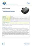
Desktop Reader Manual V2.31
08/10/2010
Desktop Reader and Wall Reader Adaptor
USER MANUAL
Version: 2.31
Distribution: SALTO customers
DOCUMENT REVISIONS
Version
Date
Modifications
1.2
5/03/2004
1.3
11/03/2004
Note on Wall Reader Adaptor about minimum wall
reader versions.
1.4
12/03/2004
Fixes mistake on Desktop Reader Connector.
1.5
25/03/2004
Minimum WR2000 firmware version to read ROM
code from iButtonROM.
1.6
11/08/2005
NEW: ROM code configuration.
BCD Data Format (ANSI/ISO): It is used in Track 2
and Track 3.
New Card Technologies (Mifare, Desfire…)
2.1
26/02/2007
New Firmware Version 02.01.
New RS232 Plain Text Format.
New Wiegand formats.
2.2
13/03/2008
New Firmware Version 02.03.
New Wiegand format.
2.3
06/06/2008
New Firmware version 02.04.
New OMRON format.
1/12
Desktop Reader Manual V2.31
08/10/2010
CONTENTS
1
Object of this document ......................................................................................................... 3
2
Desktop Reader: ECxxDR ....................................................................................................... 3
3
2.1
Desktop Reader Setup ................................................................................................. 3
2.2
Desktop Reader Connector ........................................................................................... 3
Wall Reader Adaptor: WRADAP ............................................................................................... 3
3.1
Wall Reader Connection ............................................................................................... 4
3.2
External Device Connection .......................................................................................... 4
3.3
Power Supply ............................................................................................................. 4
4
CLR Button ........................................................................................................................... 4
5
SAM programming process ..................................................................................................... 5
6
MODE dip switches table ........................................................................................................ 5
7
Data .................................................................................................................................... 6
8
9
7.1
ROM code .................................................................................................................. 6
7.2
Tracks ....................................................................................................................... 7
7.3
Wiegand code ............................................................................................................. 7
Interfaces ............................................................................................................................. 7
8.1
RS232 interface .......................................................................................................... 8
8.2
OMRON interface ........................................................................................................ 8
8.3
WIEGAND interface ..................................................................................................... 8
Formats ............................................................................................................................... 8
9.1
RS232 format with STX, ETX and Checksum ................................................................... 8
9.2
RS232 Plain Format ..................................................................................................... 9
9.3
OMRON Formats: BCD and ALPHA ................................................................................. 9
9.4
WIEGAND formats ....................................................................................................... 9
10 Card Technologies ................................................................................................................. 9
11 BCD and ALPHA ISO Standards ............................................................................................... 9
11.1
BCD Data Format (ANSI/ISO) ....................................................................................... 9
11.2
ALPHA Data Format (ANSI/ISO) .................................................................................. 10
11.3
BCD and ALPHA table ................................................................................................ 10
11.4
Non ISO cards .......................................................................................................... 11
11.5
LRC ......................................................................................................................... 11
11.6
Salto Software PMS Track Commands .......................................................................... 11
2/12
Desktop Reader Manual V2.31
08/10/2010
1
Object of this document
This document is the User Manual of two devices:
•
Desktop Reader EcxxDR.
•
Wall Reader Adaptor WRADAPT.
It covers the functions of the firmware version 02.01.
It is intended to help the PMS and T&A developers to connect their systems to the SALTO access control
system.
2
Desktop Reader: ECxxDR
The purpose of the Desktop Reader is to read some data from the cards and give them in a simple
manner to an external device, usually a Point Of Sale (POS) terminal.
The Desktop Reader has the same aspect of the RS232 Encoder. It has a 9 pins D-type connector
(female) to be connected to the RS232 port of the POS terminal. There are as many Desktop Readers as
technologies (Dallas, Smart Card, Legic Proximity) with references EC20DR, EC50DR and EC80DR.
The interface can be also OMRON and WIEGAND, depending on the dipswitch settings.
2.1
Desktop Reader Setup
The Desktop Reader comes from factory prepared to read Track1 and to give the data through RS232
interface at 19200 bauds, 8 bits and no parity. If other configuration is desired, the case has to be
opened, removing the bottom 4 screws, to have access to the Configuration Dipswitches.
Also, the reader part of the Desktop Reader has been connected and tested in the factory so it is no
necessary to use the CLR button except in Proximity readers when you need to enter a new SAM card.
The CLR button is only accessible opening the case of the Desktop Reader.
2.2
Desktop Reader Connector
The functions of the 9 pins D-type connector are different depending on the selected type of interface:
Interface
D-Type connector pins
2
3
5
RS232
TX
RX
GND
OMRON
DATA
CLOCK
GND
D1
D0
GND
WIEGAND
The Desktop Reader is powered from a plug-in 12V power supply though the jack connector. Central pin
is the positive.
The Desktop Reader is continuously looking for a card and when one is presented it sends the data to
the external device giving simultaneously a valid signal (green led and beep).
3
Wall Reader Adaptor: WRADAP
The purpose of the Wall Reader Adaptor is to read some data from the cards and give them in a simple
manner to an external device, usually a Time and Attendance (T&A) terminal.
The Wall Reader Adaptor is connected by one side to any Salto Wall Reader, WR2000 (WR1000 is not
accepted), WR5000, WR8000, WR7000, WR9000 and by the other side to the external device. There is
only one model of Wall Reader Adaptor (WRADAP) because it is compatible with Wall Readers of
different technologies.
Note: The minimum version of wall readers WR2000 (iButton) and WR5000 (Smart) is V2.20
manufactured from 22/10/2003. Previous versions do not work with Track and Wiegand data. Minimum
version to read ROM code from iButtonROM of the WR2000 is V2.41 manufactured from 25/03/2004.
Proximity readers WR7000, WR8000, WR90000 are compatible from the beginning.
3/12
Desktop Reader Manual V2.31
08/10/2010
3.1
Wall Reader Connection
The Wall Reader is connected to the Adaptor through a 5 pins block connector identical to the CU5000.
The functions of the 5 pins are:
3.2
1
5 volts power supply (from Adaptor to Wall Reader)
2
PPD connection (not used)
3
Ground
4
Data input-output
5
Card Present
External Device Connection
The interface with the external device can be RS232, OMRON and WIEGAND. The connection is made
through a 4 pins block terminal.
The functions of the 4 pins connector are different depending on the selected type of interface:
Interface Connector
Rx/D0
Tx/D1
GND
+V
RS232
RX
TX
GND
+V
OMRON
CLOCK
DATA
GND
+V
D0
D1
GND
+V
WIEGAND
The Wall Reader Adaptor is powered from the external device through pins +V and GND. Optionally can
be powered through the jack connector.
The Wall Reader Adaptor is continuously looking for a card and when one is presented it sends the data
to the external device giving simultaneously a valid signal (green led and beep).
3.3
Power Supply
Desktop Reader and Wall Reader Adaptor needs a DC power supply with a voltage between 7 and 15
volt.
The typical current consumption is 15 mA (maximum 30 mA) plus the current consumption of the reader
that depends on the technology:
Reader Consumption (mA)
Reader
Total Consumption (mA)
Technology
Typical
Maximum
Typical
Maximum
WR2000
iButton
15
30
30
60
WR5000
Smart Card
20
80
35
110
WR8000
Legic
30
50
45
80
WR9000
Mifare
40
120
55
150
WR7000
Picopass
20
60
35
90
4
CLR Button
The CLR Button permits to make a quick diagnosis of the reader. When pressing the CLR button the Led
beside the button lights and the Reader gives an orange light as long as the CLR button remains
pressed.
4/12
Desktop Reader Manual V2.31
08/10/2010
The CLR Led lights for a moment each time a card is read with the proper data according to the MODE
dipswitches setting.
5
SAM programming process
Some installations working with Mifare, Desfire, Picopass or Legic cards need to program all the readers
with the SAM card that carries the Custom-Code. To do that follow the corresponding process:
•
DeskTop Reader: the CLR button has to be kept pressed until the Encoder accepts the SAM
card. If the CLR button is released before finishing the launching process it will be stopped.
•
Wall Reader Adaptor: press and release the CLR button of the WRADAP and the reader will
start a 60 seconds period to enter the SAM card.
SAM cards are accepted in one or two seconds except Legic SAM that lasts around 15 seconds.
6
MODE dip switches table
MODE
Notes
Data
Interface
Format
00000001
Track1
RS232 (19200-8-N)
(STX, ETX, LRC)
00000010
Track2
RS232 (19200-8-N)
(STX, ETX, LRC)
00000011
Track3
RS232 (19200-8-N)
(STX, ETX, LRC)
00000100
% + ROM14 + ?
RS232 (19200-8-N)
(STX, ETX, LRC)
00000101
Track1
RS232 (9600-8-N)
(STX, ETX, LRC)
00000110
Track2
RS232 (9600-8-N)
(STX, ETX, LRC)
00000111
Track3
RS232 (9600-8-N)
(STX, ETX, LRC)
00001000
% + ROM14 + ?
RS232 (9600-8-N)
(STX, ETX, LRC)
00001001
1
Track1
RS232 (19200-8-N)
(PLAIN)
00001010
1
Track2
RS232 (19200-8-N)
(PLAIN)
00001011
1
Track3
RS232 (19200-8-N)
(PLAIN)
00001100
1
ROM14
RS232 (19200-8-N)
(PLAIN)
11000000
5
Track1
OMRON
BCD or ALPHA
11000001
5
Track2
OMRON
BCD or ALPHA
11000010
5
Track3
OMRON
BCD or ALPHA
11000011
5
% + ROM14 + ?
OMRON
ALPHA
11000100
Track1
WIEGAND
BCD or ALPHA
11000101
Track2
WIEGAND
BCD or ALPHA
11000110
Track3
WIEGAND
BCD or ALPHA
11000111
% + ROM14 + ?
WIEGAND
ALPHA
11001000
ROM
WIEGAND
56-bit
5/12
Desktop Reader Manual V2.31
08/10/2010
MODE
Notes
11001001
Data
Interface
Format
ROM
WIEGAND
56-bit + 2 paritybits
WIEGAND-CODE
WIEGAND
Format defined in
ProAccess software
11001010
1
11001011
1, 4
Facility Code zero (8
bits) plus the two lower
bytes of the Serial
Number (16 bits) plus
two parity bits.
WIEGAND
Standard 26-bit
11001100
1, 4
Three lower bytes of
the Serial Number (24
bits) plus two parity
bits.
WIEGAND
Standard 26-bit
11001101
2, 4
Four lower bytes of the
Serial Number (32 bits)
plus two parity bits.
WIEGAND
32-bit + 2 paritybits
11001110
3, 5, 6
Track2
OMRON
BCD or ALPHA
(1) Only available from firmware version 02.01.
(2) Only available from firmware version 02.03.
(3) Only available from firmware version 02.04.
(4) Only valid for Mifare, Desfire and Vicinity cards.
(5) Used not very often. Kept only for backward compatibility purpouses.
(6) The leading and trailing zeros are not appended.
7
Data
There are three types of data to be read by the Desktop Reader (or Wall Reader Adaptor):
ROM code or Serial Number
This is a factory programmed code particular for each card
TRACKS
Emulates the Tracks 1, 2 and 3 of the magnetic stripe cards.
WIEGAND CODE
Emulates de Wiegand code of access control cards
7.1
ROM code
The Salto ROM code is a 7 byte code different for each card. Normally each byte is expressed as a
double hexadecimal character so the total ROM code will be 14 ASCII characters (called ROM14). If the
bytes are represented by their 8 bits the total 56 bits representation is called ROM56.
Example:
Format
ROM6
ROM5
ROM4
ROM3
ROM2
ROM1
ROM0
Bytes
0x11
0x22
0x33
0x44
0x55
0x66
0x77
ROM14
“11223344556677”
ROM56
00010001001000100011001101000100010101010110011001110111
6/12
Desktop Reader Manual V2.31
08/10/2010
7.1.1
ROM code and Serial Number
The relation between the ROM code and the card Serial Number depends on the technology of the card.
This table shows the
ROM6
ROM5
ROM4
ROM3
ROM2
ROM1
ROM0
iButton
FamilyCode
SN5
SN4
SN3
SN2
SN1
SN0
Smart Card
SLE4442
ICCF2
ICCF3
ICCF4
ICCSN0
ICCSN1
ICCSN2
ICCSN3
IDN0
IDN1
IDN2
IDN3
IDN4
IDN5
IDN6
Legic
0x01
MCD
MSN
MSN
MSN
MCC
0x00
Mifare
UID0
UID1
UID2
UID3
0x00
0x00
0x00
UID0
UID1
UID2
UID3
UID4
UID5
UID6
SLE5542
Smart Card
AT88SC153
AT88SC1608
Desfire
Vicinity
IButton: Salto ROM code is the laser-programmed Dallas ROM code including at the beginning the
FamilyCode, followed by the Serial Number MSB and excluding the 8th byte that is a checksum. These 7
bytes are engraved on the iButton case, FamilyCode on the right and below it the other 6 bytes.
Smart Card SLE4442/SLE5542: The first three bytes are part of the IC Card Manufacturer Code. Next
four bytes are the IC Card Serial Number.
Smart Card AT88SC153 and AT88SC1608: The seven bytes of the Identification Number starting by
the LSB.
Legic: First byte is 0x01 (inexistent iButton FamilyCode), 5 bytes of the Serial Number starting by the
MDC (Manufacture Code) and finishing by the MCC (Manufacture Check Character) and a final null byte
0x00.
Mifare: The first four bytes are the Unique Identifier (UID) also called Serial Number (SN) of the Mifare
card starting by the LSB. Followed by three null bytes (0x00).
Desfire: The seven bytes of the card UID (or Serial Number SN) starting by the LSB.
ISO15693 Vicinity Cards: The seven lower bytes of the UID (or Serial Number SN) starting by the LSB
and removing the UID7 that is always 0xE0 in ISO15693 cards. PicoPass cards are included in this type.
7.2
Tracks
They emulate the tracks of the magnetic stripe cards. There are three Tracks available, TRACK1,
TRACK2 and TRACK3. The information in the emulated tracks are ASCII characters. However, in the
magnetic stripe cards, TRACK1 carries alphanumeric data and TRACK2 and TRACK3 only carry numeric
data.
7.3
Wiegand code
It is a special track in the cards (called WiegandCode) that carries information of the Wiegand code.
8
Interfaces
There are three types of electrical interface to the terminal:
•
RS232 (with different baud rates)
•
OMRON (Clock and Data)
•
Wiegand (D0 and D1)
7/12
Desktop Reader Manual V2.31
08/10/2010
8.1
RS232 interface
The RS232 voltage levels do not follow the standard because they do not give negative voltage but work
properly with the modern RS232 interface chips. They use only Rx and Tx without hardware and
software handshake.
Logical Data
Rx (volts)
Tx (volts)
Zero (0)
> 1.2
5
One (1)
<1
0.4
The baud rate, the number of bits (7 or 8) and the parity (N, E, O) are selected in the MODE dipswitch.
8.2
OMRON interface
The OMRON interface emulates the magnetic card readers. The OMRON interface has two outputs: Clock
and Data. The Clock and Data outputs in standby are 5 volts. The Data line is negated: 5 volts for a
logical Zero and 0 volts for a logical One.
The bit time is 150 us. The Clock remains in the low state 50 us. The Data line has the valid level 50 us
before the falling edge of the Clock and is kept valid 50 us after the rising edge of the Clock. So, the
terminals can read the Data with the falling or with the rising edge of the Clock, as they prefer. The
speed is comparable with magnetic card readers reading tracks of 75 and 210 bpi.
8.3
WIEGAND interface
The Wiegand interface has two outputs: Data0 and Data1. In standby they have 5 volts through 1
Kohms resistor. They represent the corresponding logical level giving a 0 volts pulse (0.4 volts through
47 ohms resistor). The width of the pulse is 90 us and the interval between pulses is 1 ms.
9
Formats
The data can be sent using different encoding tables and adding in some cases control characters and
checksums. Some formats are specific for only one interface, others are common to various interfaces.
9.1
RS232 format with STX, ETX and Checksum
The transmitted characters are all printable ASCII characters except 2 control characters that helps to
determine where the message starts and finishes:
STX
0x02
Start of message
ETX
0x03
End of message
The frame of the message is:
STX
DATA
ETX
Checksum
0x02
N characters
0x03
1 byte
The Checksum is calculated as the OR Exclusive of all the previous bytes including the STX and ETX. If
the manufacturer of the external device wants to simplify the software can skip the Checksum testing.
Depending on the source of data the N characters of the DATA are:
•
Track1, Track2, Track3: exactly the same string of ASCII characters given by the PMS to the
HAMS through the Track command.
•
ROM14: ROM code of the key expressed as 14 hexadecimal ASCII characters. Each byte of the
ROM Code is expressed with two ASCII hex characters. A Start Sentinel (“%”) and End Sentinel
(“?”) are added.
8/12
Desktop Reader Manual V2.31
08/10/2010
9.2
RS232 Plain Format
It transmits the ASCII characters of Data without STX, ETX and Checksum.
9.3
OMRON Formats: BCD and ALPHA
The ASCII characters of Data have to be translated to BCD or ALPHA codes (see BCD and ALPHA ISO )
before be sent through the OMRON interface. This format is also available for Wiegand.
9.3.1
BCD or ALPHA format
The standard specifies BCD encoding for Track2 and Track3 and ALPHA encoding for Track1 but it is
usual that applications do not follow this rule. To permit these exceptions, the encoding is not selected
depending on the Track but on the data carried by the Track. The rule to determine which encoding to
be used (BCD or ALPHA) with the Tracks is:
•
If all the ASCII characters of the Track are included in the BCD symbol set
(0123456789:;<=>?) it uses the BCD encoding (4 bits + parity).
•
Otherwise it uses the ALPHA encoding (6 bits + parity). And if the data finishes with the End
Sentinel (?) the Reader calculates and adds the LRC.
Warning:
If the system expects ALPHA encoding care has to be taken to avoid the possibility that the information
of the Track would have only digits because in this particular case the Adaptor would encode it in BCD.
For instance, a Track carries the room number, some rooms have letters (SUITE1, 301A) but other
rooms have only digits (101, 102). To avoid encode the later in BCD the information in the Track should
always include some fixed character not included in the BCD symbol set, for instance the letter R (for
ROOM) or just a space before or after every room number.
ROM14 code is always ALPHA encoded adding the Start Sentinel (%), End Sentinel (?) and final LRC.
9.3.2
Syncronization zeros
Before and after the data, the adaptor appends 25 leading and 25 trailing zeros emulating a standard
magnetic card reader. This feature was disabled in one of the two availables OMRON modes for track2.
9.4
WIEGAND formats
Byte and bit order: Wiegand interface sends the data always Most Significant Byte First and Most
Significant Bit First.
Parity bits: The two parity bits are one Even parity bit of the first half bits at the beginning and one
Odd parity bit of the last half bits at the end.
Data for Wiegand is usually ROM code and Serial Number, notice that they are not exactly the same,
please find in ROM code and Serial Number the relation between them.
In some configurations Wiegand uses the same formats BCD and ALPHA of the OMRON interface. It
sends the bits in the same order they would be sent through the OMRON (Clock and Data) interface, but
without adding leading and trailing zeros.
10 Card Technologies
The Desktop Reader and Wall Reader Adaptor are available for all RW technologies: iButton, Smart
Cards and Proximity. There are some few exceptions:
•
ArenaCards (NAGRA) are not included because they cannot carry Tracks or Wiegand Code,
neither do have ROM code.
•
I2C smart cards have no ROM Code but can have Track 1, 2 and 3 and Wiegand Code.
•
In Legic cards the systems can only read the ROM code of cards with a Salto segment.
11 BCD and ALPHA ISO Standards
The data of tracks 1, 2 and 3 of magnetic stripe cards can be encoded in two ways: BCD and ALPHA
formats.
11.1
BCD Data Format (ANSI/ISO)
It is used in Track 2 and Track 3.
9/12
Desktop Reader Manual V2.31
08/10/2010
Set of characters: 16 characters of 5 bits (4 bits + odd parity). LSB first (Least Significant Bit first) and
Parity Bit last. BCD Value = ASCII value – 0x30.
11.2
ALPHA Data Format (ANSI/ISO)
It is used by Track 1.
Set of characters: 64 characters of 7 bits (6 bits + odd parity). ). LSB first (Least Significant Bit first)
and Parity Bit last. ALPHA value = ASCII value – 0x20.
11.3
BCD and ALPHA table
This table shows the symbols of the BCD and ALPHA formats and the equivalences with their
representation as printable characters and ASCII values.
Printable
ASCII value
BCD codes
ALPHA codes
characters
(1 byte)
(4 bits + parity)
(6 bits + parity)
Space
0x20
00
!
0x21
01
“
0x22
02
#
0x23
03
$
0x24
04
%
0x25
05 (SS)
&
0x26
06
´
0x27
07
(
0x28
08
)
0x29
09
+
0x2A
0A
*
0x2B
0B
,
0x2C
0C
-
0x2D
0D
.
0x2E
0E
/
0x2F
0F
0
0x30
00
10
1
0x31
01
11
2
0x32
02
12
3
0x33
03
13
4
0x34
04
14
5
0x35
05
15
10/12
Desktop Reader Manual V2.31
08/10/2010
Printable
ASCII value
BCD codes
ALPHA codes
characters
(1 byte)
(4 bits + parity)
(6 bits + parity)
6
0x36
06
16
7
0x37
07
17
8
0x38
08
18
9
0x39
09
19
:
0x3A
0A
1A
;
0x3B
0B (SS)
1B
<
0x3C
0C
1C
=
0x3D
0D (FS)
1D
>
0x3E
0E
1E
?
0x3F
0F (ES)
1F (ES)
@
0x40
20
A
0x41
21
…letters..
…
…
Z
0x5A
3A
[
0x5B
3B
\
0x5C
3C
]
0x5D
3D
^
0x5E
3E (FS)
_
0x5F
3F
(SS) = Start Sentinel
(FS) = Field Separator
(ES) = End Sentinel
11.4
Non ISO cards
Not all the cards follow exactly the ISO standards in the tracks.
Some cards do not limit the use of BCD codes to Track2 and 3 or ALPHA codes to Track1, some others
do not use the standard Sentinels or Field Separators.
11.5
LRC
The LRC (Longitudinal Redundancy Code) is the exclusive OR (XOR) including the Start and End
Sentinels (SS and ES) in both formats BCD and ALPHA. Its parity is also odd.
11.6
Salto Software PMS Track Commands
The PMS commands for Tracks sends the data in ASCII format. They never add the LRC because the
XOR of the characters can give a non-ASCII character and be equal to a control character of the link
PMS-HAMS producing a malfunction. The Desktop Reader and the Wall Reader Adaptor will calculate and
11/12
Desktop Reader Manual V2.31
08/10/2010
add the LRC in OMRON and WIEGAND interfaces if the data of the Track string finishes with the End
Sentinel (“?”).
12/12