1
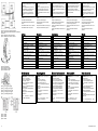
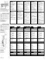
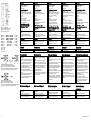
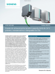
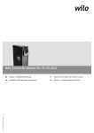
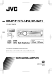
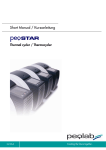
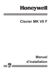
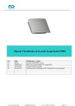
DEUTSCH
SITOP UPS1600 10A
6EP4134-3AB00-0AY0
6EP4134-3AB00-1AY0
6EP4134-3AB00-2AY0
SITOP UPS1600 20A
6EP4136-3AB00-0AY0
6EP4136-3AB00-1AY0
6EP4136-3AB00-2AY0
SITOP UPS1600 40A
6EP4137-3AB00-0AY0
6EP4137-3AB00-1AY0
6EP4137-3AB00-2AY0
Betriebsanleitung (kompakt)
Operating Instructions (compact)
Notice de service (compacte)
Istruzioni operative (descrizione sintetica)
Instrucciones de servicio (resumidas)
ITALIANO
ESPAÑOL
Description
Description
Descrizione
Descripción
siehe Bild 1 Ansicht Geräte (Seite 1)
siehe Bild 2 Verdrahtung PSU, UPS1600 und
UPS1100 (Seite 2)
See Figure 1 View of the devices (Page 1)
See Figure 2 Wiring of the PSU, UPS1600 and
UPS1100 (Page 2)
voir Figure 1 Vue des appareils (Page 1)
voir Figure 2 Câblage de l'unité d'alimentation
(PSU), de l'UPS1600 et de l'UPS1100 (Page 2)
vedere Figura 1 Vista degli apparecchi
(Pagina 1)
Ver Figura 1 Vista de aparatos (Página 1)
Ver Figura 2 Cableado de PSU, UPS1600 y
UPS1100 (Página 2)
Sicherheitshinweise
Safety notes
Consignes de sécurité
Avvertenze di sicurezza
Die SITOP UPS1600 sind Einbaugeräte,
Schutzart IP20. In Kombination mit SITOP
Batteriemodulen SITOP UPS1100 (max. 6)
dient es zur Pufferung von Lastströmen DC
24 V bis 10 A, 20 A, 40 A.
SITOP UPS1600 are built-in devices, IP20
degree of protection. In combination with
SITOP battery modules, SITOP UPS1100
(max. 6) devices are used to buffer load
currents up to 10 A, 20 A, 40 A at 24 V DC.
Les SITOP UPS1600 sont des appareils
encastrables avec degré de protection IP20.
En association avec les blocs-batterie SITOP,
les SITOP UPS1100 (max. 6) servent au
maintien des courants de charge 24 V CC
jusqu'à 10 A, 20 A, 40 A.
I SITOP UPS1600 sono apparecchi da
incasso con grado di protezione IP20.
Associato ai moduli batteria SITOP, il SITOP
UPS1100 (max. 6) assicura il tamponamento
delle correnti di carico DC 24 V fino a 10 A,
20 A, 40 A.
vedere Figura 2 Cablaggio PSU, UPS1600 e
UPS1100 (Pagina 2)
Las SITOP UPS1600 son modelos
empotrables con grado de protección IP20.
En combinación con los módulos de batería
SITOP, SITOP UPS1100 (máx. 6)
proporciona respaldo para intensidades de
carga DC de 24 V hasta 10 A, 20 A, 40 A.
Consignas de seguridad
ACHTUNG
NOTICE
IMPORTANT
ATTENZIONE
ATENCIÓN
Der einwandfreie und sichere Betrieb dieses
Gerätes/Systems setzt sachgemäßen
Transport, sachgemäße Lagerung,
Aufstellung und Montage sowie sorgfältige
Bedienung und Instandhaltung voraus.
Appropriate transport, proper storage,
mounting, and installation, as well as careful
operation and service, are essential for the
error-free, safe and reliable operation of the
device/system.
Il funzionamento ineccepibile e sicuro di
questo apparecchio/sistema presuppone un
trasporto corretto, un immagazzinaggio
idoneo, una installazione, un montaggio, un
utilizzo e una manutenzione accurati.
Dieses Gerät/System darf nur unter
Beachtung der Instruktionen und
Warnhinweise der zugehörigen Technischen
Dokumentation eingerichtet und betrieben
werden.
Nur qualifiziertes Personal darf das
Gerät/System installieren und in Betrieb
setzen.
Setup and operation of this device/system are
permitted only if the instructions and warnings
of the corresponding documentation are
observed.
L'exploitation de cet appareil / ce système
dans les meilleures conditions de
fonctionnement et de sécurité suppose un
transport, un stockage, une installation et un
montage adéquats, ainsi qu'une manipulation
soigneuse et un entretien rigoureux.
Cet appareil / ce système ne peut être
configuré et exploité qu'à condition de
respecter les instructions et les
avertissements figurant dans la
documentation technique correspondante.
El funcionamiento correcto y seguro de este
aparato/sistema presupone un transporte, un
almacenamiento, una instalación y un
montaje conformes a las prácticas de la
buena ingeniería, así como un manejo y un
mantenimiento rigurosos.
Este aparato/sistema debe ajustarse y
utilizarse únicamente teniendo en cuenta las
instrucciones y advertencias de la
documentación técnica correspondiente.
La instalación y puesta en marcha del
aparato/sistema debe encomendarse
exclusivamente a personal cualificado.
SCHALTERBETÄTIGUNG NUR IN NICHTEXPLOSIVER UMGEBUNG DURCHFÜHREN!
Montage
Montage auf Normprofilschiene
DIN EN 60715-TH35-15/7,5.
Das Gerät ist so zu montieren, dass die
Eingangs- und Ausgangsklemmen unten
sind.
Unterhalb und oberhalb des Gerätes muss
mindestens ein Freiraum von je 50 mm
eingehalten werden.
Bei Installation des Gerätes in
explosionsgefährdeter Umgebung
(II 3G Ex nA nC IIC T4 Gc) ist dieses in einen
Verteilerkasten mit Schutzart IP54 oder höher
einzubauen. Dieser Verteilerkasten muss den
Anforderungen der EN 60079-15
entsprechen.
Only qualified personnel are allowed to install
the device/system and set it into operation.
WARNING
OPERATE SWITCHES IN NONHAZARDOUS AREAS ONLY!
Assembling
Mounted on a standard mounting rail
DIN EN 60715-TH35-15/7,5.
The device must be mounted in such a way
that the input and output terminals are at the
bottom.
A clearance of at least 50 mm must be
maintained above and below the device.
If the device is to be used in a hazardous
zone (II 3G Ex nA nC IIC T4 Gc) it must be
installed in a distribution box with degree of
protection IP54 or higher. This distribution
box must comply with the requirements of
EN 60079-15.
L'installation et la mise en service de l'appareil /
du système doit impérativement être effectué
par des personnes qualifiées.
ATTENTION
UTILISER COMMUTATEURS UNIQUEMENT
EN ZONES NON EXPLOSIBLES!
Fixation
Montage sur rail DIN
symétriqueDIN EN 60715-TH35-15/7,5
L'appareil doit être fixé de sorte que les
bornes d'entrée et les bornes de sortie se
trouvent en bas.
Un espace libre de 50 mm doit être prévu en
dessous et au-dessus de l'appareil.
Les appareils installés en atmosphères
explosibles (II 3G Ex nA nC IIC T4 Gc)
doivent être montés dans un coffret de
distribution avec indice de protection IP54 ou
supérieur. Ce coffret doit répondre aux
spécifications de la norme EN 60079-15.
Questo apparecchio/sistema deve essere
installato e impiegato nel pieno rispetto delle
istruzioni e delle avvertenze riportate nella
documentazione tecnica pertinente.
L'apparecchio/il sistema può essere installato
e messo in servizio solo da personale
qualificato.
AVVERTENZA
IMPOSTARE UTILIZZARE L’INTERRUTTORE
SOLO IN AMBIENTE NON ESPLOSIVO!
Montaggio
Montaggio su guida profilata normalizzata
DIN EN 60715-TH35-15/7,5.
L'apparecchio va montato con i morsetti
d'ingresso e quelli di uscita in basso.
Sopra e sotto l'apparecchio deve restare uno
spazio libero di almeno 50 mm.
Nel caso di installazione in aree a rischio
d'esplosione (II 3G Ex nA nC IIC T4 Gc),
l'apparecchiatura va incorporata in una
cassetta di distribuzione con grado di
protezione IP54 o superiore. Questa cassetta
di distribuzione deve essere conforme alle
specifiche della normativa EN 60079-15.
ADVERTENCIA
AJUSTAR ACCIONAR INTERRUPTORES
SÓLO EN ENTORNOS NO EXPLOSIVOS
Montaje
Montaje en perfil normalizado DIN EN 60715TH35-15/7,5.
El aparato debe montarse de modo que los
bornes de entrada y salida queden abajo.
Por encima y por debajo del aparato debe
dejarse un espacio libre de al menos 50 mm.
Si se va a instalar el aparato en una
atmósfera potencialmente explosiva
(II 3G Ex nA nC IIC T4 Gc), deberá montarse
en una caja de distribución con grado de
protección IP54 o superior. Esta caja debe
cumplir los requisitos de EN 60079-15.
siehe Bild 3 Montage / Demontage (Seite 2)
See Figure 3 Mounting/removal (Page 2)
voir Figure 3 Montage/démontage (Page 2)
vedere Figura 3 Montaggio / smontaggio (Pagina 2)
Ver Figura 3 Montaje/desmontaje (Página 2)
Anschließen
Connecting
Raccordement
Collegamento
Conexión
WARNUNG
© Siemens AG 2014. All rights reserved
A5E35375408, 11.2014
FRANÇAIS
Beschreibung
WARNUNG
Bild 1: Ansicht Geräte
Figure 1: View of the devices
Figure 1: Vue des appareils
Figura 1: Vista degli apparecchi
Figura 1: Vista de aparatos
ENGLISH
Vor Beginn der Installations- oder
Instandhaltungsarbeiten ist der Hauptschalter
der Anlage auszuschalten und gegen
Wiedereinschalten zu sichern. Bei
Nichtbeachtung kann das Berühren
spannungsführender Teile Tod oder schwere
Körperverletzung zur Folge haben.
Die Betätigung der Drehkodierschalter ist nur
mittels isoliertem Schraubendreher zulässig.
WARNING
Before installation or maintenance work can
begin, the system's main switch must be
switched off and measures taken to prevent it
being switched on again. If this instruction is
not observed, touching live parts can result in
death or serious injury.
It is only permissible to actuate the rotary
coding switch using an insulated screwdriver.
ATTENTION
Avant de commencer les travaux d'installation
ou de maintenance, couper l'interrupteur
général de l'installation et le condamner pour
empêcher la remise sous tension. Le nonrespect de cette consigne peut entraîner la
mort ou des blessures graves en cas de
contact avec des pièces sous tension.
Actionner la roue codeuse uniquement à
l'aide d'un tournevis isolé.
AVVERTENZA
Prima dell'inizio dei lavori di installazione o
manutenzione è necessario disinserire
l'interruttore principale dell'impianto e
assicurarlo contro la reinserzione. In caso di
mancata osservanza, il contatto con parti
sotto tensione può provocare la morte o gravi
lesioni personali.
Il selettore rotante di codifica si deve azionare
solo mediante un cacciavite isolato.
ADVERTENCIA
Antes de comenzar los trabajos de instalación
o mantenimiento, se deberá abrir el
interruptor principal del cuadro/tablero y
protegerlo para evitar su cierre. Si no se
observa esta medida, el contacto con piezas
bajo tensión puede provocar la muerte o
lesiones graves.
El conmutador rotativo solo deberá girarse
usando un destornillador aislado.
1
Für die Installation der Geräte sind die
einschlägigen länderspezifischen Vorschriften
zu beachten.
Die Versorgungsspannung 24 V DC muss
den Anforderungen an SELV-Kreise nach
EN 60950-1 und EN 50178 genügen.
Es sind Leitungen zu verwenden, die für
mindestens 90 °C geeignet sind (nur bei
UL508).
Bild 2: Verdrahtung PSU, UPS1600 und UPS1100
Figure 2: Wiring of the PSU, UPS1600 and UPS1100
Figure 2: Câblage de l'unité d'alimentation (PSU), de l'UPS1600 et
de l'UPS1100
Figura 2: Cablaggio PSU, UPS1600 e UPS1100
Figura 2: Cableado de PSU, UPS1600 y UPS1100
Bild 4: ① Input / ② Output / ③ Bat
Figure 4: ① Input / ② Output / ③ Bat
Figure 4: ① Entrée / ② Sortie / ③ Bat
Figura 4: ① Input / ② Output / ③ Bat
Figura 4: ① Entrada/② Salida/③ Bat
L'installation des appareils doit se faire en
conformité avec les prescriptions nationales.
La tension d'alimentation 24 V CC doit
répondre aux exigences relatives aux circuits
TBTS (SELV) conformément à EN 60950-1 et
EN 50178.
Il faut utiliser des câbles admissibles pour au
moins 90 °C (uniquement pour UL508).
Per l'installazione degli apparecchi occorre
osservare le normative nazionali vigenti.
La tensione di alimentazione 24 V DC deve
soddisfare i requisiti dei circuiti SELV in
conformità a EN 60950-1 e EN 50178.
I conduttori per almeno 90 °C devono esser
usati (solo per UL508).
A la hora de instalar los aparatos, se tienen
que observar las disposiciones o normativas
específicas de cada país.
La tensión de alimentación de 24 V DC debe
cumplir los requisitos para circuitos SELV
según EN 60950-1 y EN 50178.
Los cables que están servidos para por lo
menos 90 °C deben ser usados (solo con
UL508).
siehe Bild 4 ① Input / ② Output / ③ Bat
(Seite 2)
See Figure 4 ① Input / ② Output / ③ Bat
(Page 2)
voir Figure 4 ① Entrée / ② Sortie / ③ Bat
(Page 2)
vedere Figura 4 ① Input / ② Output / ③ Bat
(Pagina 2)
Ver Figura 4 ① Entrada/② Salida/③ Bat
(Página 2)
siehe Bild 5 Schnittstellen (Seite 2)
siehe Bild 6 Signalstecker Anschlussschema
(Seite 3)
siehe Bild 7 Klemmdaten 10 A, 20 A (Seite 3)
See Figure 5 Interfaces (Page 2)
See Figure 6 Signal connector connection
schematic (Page 3)
See Figure 7 Terminal data 10 A, 20 A (Page 3)
siehe Bild 8 Klemmdaten 40 A (Seite 3)
See Figure 8 Terminal data 40 A (Page 3)
voir Figure 5 Interfaces (Page 2)
voir Figure 6 Schéma de raccordement des
connecteurs de signaux (Page 3)
voir Figure 7 Caractéristiques des bornes 10 A,
20 A (Page 3)
voir Figure 8 Caractéristiques des bornes 40 A
(Page 3)
vedere Figura 5 Interfacce (Pagina 2)
vedere Figura 6 Schema di collegamento del
connettore di segnale (Pagina 3)
vedere Figura 7 Dati dei morsetti 10 A, 20 A
(Pagina 3)
vedere Figura 8 Dati dei morsetti 40 A
(Pagina 3)
Ver Figura 5 Interfaces (Página 2)
Ver Figura 6 Esquema de conexiones del
conector de señales (Página 3)
Ver Figura 7 Datos de los bornes 10 A, 20 A
(Página 3)
Ver Figura 8 Datos de los bornes 40 A
(Página 3)
Aufbau
Structure
Constitution
Struttura
Diseño
①
②
③
④
⑤
DC-Eingang
DC-Ausgang
BAT
Signalstecker
⑦
PROFINET- (Ethernet-) Schnittstelle
(nur bei ... - 2AY0)
USB - Schnittstelle
(nur bei ... - 1AY0)
Drehkodierschalter Zuschaltschwelle
⑧
①
②
③
④
⑤
DC input
DC output
BAT
Signal connector
①
②
③
④
⑤
⑦
PROFINET (Ethernet) interface
(only for ... - 2AY0)
USB interface
(only for ... - 1AY0)
Rotary coding switch, switch-in threshold
Drehkodierschalter Pufferzeit
⑧
Rotary coding switch, buffer time
⑧
⑨
⑩
Signalisierung (LEDs)
⑨
⑩
Signaling (LEDs)
⑨
⑩
⑪
⑫
Konvektion
⑪
⑫
Convection
⑥
Bild 3: Montage / Demontage
Figure 3: Mounting/removal
Figure 3: Montage/démontage
Figura 3: Montaggio / smontaggio
Figura 3: Montaje/desmontaje
For installation of the devices, the relevant
country-specific regulations must be
observed.
The 24 V DC supply voltage must comply
with the requirements for SELV circuits
according to EN 60950-1 and EN 50178.
Use wires suitable for at least 90 °C (only for
UL508).
Hutschienenschieber
Freiraum oberhalb/unterhalb
⑥
DIN rail slider
Clearance above/below
⑥
⑦
⑪
⑫
Entrée CC
Sortie CC
BAT
Connecteur de signaux
Interface PROFINET (Ethernet)
(uniquement pour ... - 2AY0)
Interface USB
(uniquement pour ... - 1AY0)
Roue codeuse Seuil de mise sous
tension
Roue codeuse Temps de maintien
Signalisation (LED)
Coulisseau de fixation sur rail DIN
symétrique
Convection
Espace libre au-dessus / en dessous
①
②
③
④
⑤
⑥
⑦
⑧
⑨
⑩
⑪
⑫
Ingresso DC
Uscita DC
BAT
Connettore di segnale
Interfaccia PROFINET (Ethernet)
(solo per ... - 2AY0)
Interfaccia USB
(solo per ... - 1AY0)
Soglia di intervento del selettore rotante
di codifica
Tempo di tamponamento del selettore
rotante di codifica
Segnalazione (LED)
Dispositivo di aggancio per guida
profilata
Convezione
Spazio libero superiore/inferiore
①
②
③
④
⑤
⑥
⑦
⑧
⑨
⑩
⑪
⑫
Entrada DC
Salida DC
BAT
Conector de señales
Interfaz PROFINET (Ethernet)
(solo con ... - 2AY0)
Interfaz USB
(solo con ... - 1AY0)
Umbral de conmutación del conmutador
rotativo
Tiempo de respaldo del conmutador
rotativo
Señalización (LED)
Corredera de fijación a perfil
Convección
Espacio libre arriba/abajo
siehe Bild 9 Gesamtaufbau (Seite 3)
See Figure 9 Overall structure (Page 3)
voir Figure 9 Constitution (Page 3)
vedere Figura 9 Struttura completa (Pagina 3)
Ver Figura 9 Diseño general (Página 3)
Betriebsmodus
Operating mode
Mode de fonctionnement
Modo operativo
Modo de servicio
Signalisierung
LED1: grün/gelb/rot – Betriebsart UPS1600
LED2: grün – Ladezustand
LED3: rot – Pufferbereitschaft
LED4: rot/gelb – Akkutest
LED5: rot – für PROFINET spezifische
Diagnoseanzeigen
LED6: grün – für PROFINET spezifische
Diagnoseanzeigen
LED7: grün/gelb – Verbindungszustand
Ethernet Port 2
LED8: grün/gelb – Verbindungszustand
Ethernet Port 1
LED 5 … 8 sind nur bei ... -2AY0 aktiv
siehe Bild 11 LEDs (Seite 4)
Signaling
LED1: green/yellow/red – operating mode
UPS1600
LED2: green – charge state
LED3: red – ready for buffering
LED4: red/yellow – battery test
LED5: red – specific diagnostic displays for
PROFINET
LED6: green – specific diagnostic displays for
PROFINET
LED7: green/yellow – connection state,
Ethernet Port 2
LED8: green/yellow – connection state
Ethernet Port 1
LED 5 … 8 are only active for ... -2AY0
See Figure 11 LEDs (Page 4)
Signalisation
LED1 : vert/jaune/rouge – Mode de
fonctionnement UPS1600
LED2 : vert – Etat de chargement
LED3 : rouge – Etat prêt au maintien
LED4 : rouge/jaune – Test de l'accumulateur
LED5 : rouge – pour les affichages de
diagnostic spécifiques à PROFINET
LED6 : vert – pour les affichages de
diagnostic spécifiques à PROFINET
LED7 : vert/jaune – Etat de connexion
Ethernet Port 2
LED8 : vert/jaune – Etat de connexion
Ethernet Port 1
Les LED 5 … 8 sont actives uniquement pour
... -2AY0
voir Figure 11 LED (Page 4)
Segnalazione
LED1: verde/giallo/rosso – modo operativo
UPS1600
LED2: verde – stato di carica
LED3: rosso – disponibilità batteria tampone
LED4: rosso/giallo – test accumulatore
LED5: rosso – segnalazioni specifiche per
PROFINET
LED6: verde – segnalazioni diagnostiche
specifiche per PROFINET
LED7: verde/giallo – stato connessione
Ethernet Port 2
LED8: verde/giallo – stato connessione
Ethernet Port 1
LED 5 ... 8 attivi solo con ... -2AY0
vedere Figura 11 LED (Pagina 4)
Señalización
LED1: verde/amarillo/rojo: modo de
operación UPS1600
LED2: verde: estado de carga
LED3: rojo: disponibilidad de respaldo
LED4: rojo/amarillo: comprobación de la
batería
LED5: rojo: indicadores de diagnóstico
específicos para PROFINET
LED6: verde: indicadores de diagnóstico
específicos para PROFINET
LED7: verde/amarillo: estado de conexión de
Ethernet Port 2
LED8: verde/amarillo: estado de conexión de
Ethernet Port 1
LED 5 … 8 solo están activos con ... -2AY0
Ver Figura 11 LED (Página 4)
Bild 5: Schnittstellen
Figure 5: Interfaces
Figure 5: Interfaces
Figura 5: Interfacce
Figura 5: Interfaces
2
A5E35375408, 11.2014
Bild 6: Signalstecker Anschlussschema
Figure 6: Signal connector connection schematic
Figure 6: Schéma de raccordement des connecteurs de signaux
Figura 6: Schema di collegamento del connettore di segnale
Figura 6: Esquema de conexiones del conector de señales
Bild 7: Klemmdaten 10 A, 20 A
Figure 7: Terminal data 10 A, 20 A
Figure 7: Caractéristiques des bornes 10 A, 20 A
Figura 7: Dati dei morsetti 10 A, 20 A
Figura 7: Datos de los bornes 10 A, 20 A
Bild 8: Klemmdaten 40 A
Figure 8: Terminal data 40 A
Figure 8: Caractéristiques des bornes 40 A
Figura 8: Dati dei morsetti 40 A
Figura 8: Datos de los bornes 40 A
Bild 9: Gesamtaufbau
Figure 9: Overall structure
Figure 9: Constitution
Figura 9: Struttura completa
Figura 9: Diseño general
A5E35375408, 11.2014
Drehkodierschalter
2 Schalter zur Einstellung der Zuschaltschwelle und Pufferzeit
Schalterstellung REN: Zuschaltschwelle und
Pufferzeit über Software einstellen
Bei Geräten ohne Schnittstelle (… - 0AY0)
existiert die Funktion REN nicht.
Auslieferzustand:
Zuschaltschwelle: 22,5 V
Pufferzeit: MAX
siehe Bild 12 Drehkodierschalter
Zuschaltschwelle (Seite 4)
siehe Bild 13 Drehkodierschalter Pufferzeit
(Seite 4)
Relais
REL1 (Wechsler):
Arbeitsstellung: Normalbetrieb
Ruhestellung: Pufferbetrieb oder Aus
REL2 (Wechsler):
Arbeitsstellung: Pufferbetrieb ist möglich
Ruhestellung: fehlende Pufferbereitschaft
Takt 0,25 Hz: Akku defekt
REL3 (Schließer):
Arbeitsstellung: Pufferung der eingestellten
Pufferzeit ist möglich, bzw. Ladezustand
>85 %
siehe Bild 6 Signalstecker Anschlussschema
(Seite 3)
Rotary coding switches
2 switches to set the switch-in threshold and
buffer time
switch position REN: Set the switch-in
threshold and buffer time using the software
The REN function does not exist for devices
without (… - 0AY0).
Delivery state:
Switch-in threshold: 22.5 V
Buffer time: MAX
See Figure 12 Rotary coding switch, switch-in
threshold (Page 4)
See Figure 13 Rotary coding switch, buffer
time (Page 4)
Relays
REL1 (changeover contact):
Energized state: Normal operation
Quiescent state: Buffer mode or off
REL2 (changeover contact):
Energized state: Buffer operation is possible
Quiescent state: Not ready for buffering
Cycle 0.25 Hz: Defective battery
REL3 (NO contact):
Energized state: Buffering of the selected
buffer time is possible, or charge state >85 %
See Figure 6 Signal connector connection
schematic (Page 3)
Roue codeuse
2 commutateurs pour le réglage du seuil de
mise sous tension et du temps de maintien
Position REN du commutateur : réglage du
seuil de mise sous tension et du temps de
maintien par logiciel
Sur les appareils sans interface (… - 0AY0),
la fonction REN n'existe pas.
Etat à la livraison :
Seuil de mise sous tension : 22,5 V
Temps de maintien : MAX
voir Figure 12 Roue codeuse Seuil de mise
sous tension (Page 4)
voir Figure 13 Roue codeuse Temps de
maintien (Page 4)
Relais
REL1 (contact inverseur) :
Etat de travail : fonctionnement normal
Etat de repos : fonctionnement en mode
maintien ou arrêt
REL2 (contact inverseur) :
Etat de travail : fonctionnement en mode
maintien possible
Etat de repos : absence de l'état prêt au
maintien
Cycle 0,25 Hz : accumulateur défectueux
REL3 (contact NO) :
Etat de travail : maintien pendant la durée de
maintien réglée possible, ou état de
chargement > 85 %
voir Figure 6 Schéma de raccordement des
connecteurs de signaux (Page 3)
Selettore rotante di codifica
2 interruttori per impostare la soglia di
intervento e il tempo di tamponamento
Posizione interruttore REN: impostare via
software la soglia di intervento e il tempo di
tamponamento
Negli apparecchi senza interfaccia
(… - 0AY0) la funzione REN non esiste.
Stato di fornitura:
Soglia di intervento: 22,5 V
Tempo di tamponamento: MAX
vedere Figura 12 Soglia di intervento del
selettore rotante di codifica (Pagina 4)
vedere Figura 13 Tempo di tamponamento
del selettore rotante di codifica (Pagina 4)
Relè
REL1 (contatto di scambio):
Posizione di lavoro: Funzionamento normale
Posizione di riposo: Tamponamento oppure
OFF
REL2 (contatto di scambio):
Posizione di lavoro: Tamponamento possibile
Posizione di riposto: Tamponamento non
disponibile
Frequenza 0,25 Hz: Accumulatore guasto
REL3 (contatto normalmente aperto):
Posizione di lavoro: Tamponamento possibile
per il tempo impostato oppure stato di carica
>85 %
vedere Figura 6 Schema di collegamento del
connettore di segnale (Pagina 3)
siehe Bild 10 Betriebsmodus (Seite 4)
See Figure 10 Operating mode (Page 4)
voir Figure 10 Mode de fonctionnement (Page 4)
Technische Daten
Technical data
Caractéristiques techniques Dati tecnici
Eingangsgrößen
Eingangsnennspannung Ue nenn:
24 V DC
Eingangsspannungsbereich:
21 bis 29 V DC
Eingangsnennstrom bei 24 V:
UPS1600 10A:
Ie nenn: 12,4 A (Batterieladung)
Ie nenn: 10,5 A (Batterie geladen)
UPS1600 20A:
Ie nenn: 23,4 A (Batterieladung)
Ie nenn: 20,5 A (Batterie geladen)
UPS1600 40A:
Ie nenn: 43,4 A (Batterieladung)
Ie nenn: 40,5 A (Batterie geladen)
Leistungsaufnahme bei Volllast:
UPS1600 10A: 300 W
UPS1600 20A: 600 W
UPS1600 40A:1200 W
Ausgangsgrößen
Ausgangsnennspannung Ua nenn: 24 V
Ausgangsnennstrom Ia nenn:
UPS1600 10A:
10 A bei -25...70 °C
UPS1600 20A:
20 A bei -25...60 °C
15 A (Derating) bei 60...70 °C
UPS1600 40A:
40 A bei -25...60 °C
30 A (Derating) bei 60...70 °C
Extra Power im Betrieb:
3x Ia nenn für 30 ms
1,5x Ia nenn für 5 s
Umgebungsbedingungen
Temperatur für Betrieb:
-25… +70 °C
Verschmutzungsgrad 2
Eigenkonvektion
Input variables
Rated input voltage Ue rated:
24 V DC
Input voltage range:
21 to 29 V DC
Rated input current at 24 V:
UPS1600 10A:
Ie rated: 12.4 A (battery charge)
Ie rated: 10.5 A (battery charged)
UPS1600 20A:
Ie rated: 23.4 A (battery charge)
Ie rated: 20.5 A (battery charged)
UPS1600 40A:
Ie rated: 43.4 A (battery charge)
Ie rated: 40.5 A (battery charged)
Power consumption at full load:
UPS1600 10A: 300 W
UPS1600 20A: 600 W
UPS1600 40A:1200 W
Output variables
Rated output voltage Ua rated: 24 V
Rated output current Ia rated:
UPS1600 10A:
10 A at -25...70 °C
UPS1600 20A:
20 A at -25...60 °C
15 A (derating) at 60...70 °C
UPS1600 40A:
40 A at -25...60 °C
30 A (derating) at 60...70 °C
Extra Power in operation:
3x Ia rated for 30 ms
1.5x Ia rated for 5 s
Ambient conditions
Temperature for operation:
-25… +70 °C
Pollution degree 2
Natural convection
Valeurs d'entrée
Tension d'entrée nominale Ue nom :
24 V CC
Plage de tension d'entrée :
21 à 29 V CC
Courant d'entrée nominal à 24 V :
UPS1600 10 A :
Ie nom : 12,4 A (chargement de la batterie)
Ie nom : 10,5 A (batterie chargée)
UPS1600 20 A :
Ie nom : 23,4 A (chargement de la batterie)
Ie nom : 20,5 A (batterie chargée)
UPS1600 40 A :
Ie nom : 43,4 A (chargement de la batterie)
Ie nom : 40,5 A (batterie chargée)
Puissance absorbée à pleine charge :
UPS1600 10A: 300 W
UPS1600 20A: 600 W
UPS1600 40A:1200 W
Valeurs de sortie
Tension de sortie nominale Us nom : 24 V
Courant de sortie nominal Ia nom :
UPS1600 10 A :
10 A à -25...70 °C
UPS1600 20 A :
20 A à -25...60 °C
15 A (déclassement) à 60...70 °C
UPS1600 40 A :
40 A à -25...60 °C
30 A (déclassement) à 60...70 °C
Puissance supplémentaire en service :
3x Ia nom pendant 30 ms
1,5x Ia nom pendant 5 s
Conditions ambiantes
Température de fonctionnement
-25 à +70 °C
degré de salissement 2
Convection naturelle
vedere Figura 10 Modo di funzionamento
(Pagina 4)
Grandezze di ingresso
Tensione nominale di ingresso Ue nom:
24 V DC
Campo di tensione di ingresso:
21 ... 29 V DC
Corrente nominale di ingresso a 24 V:
UPS1600 10A:
Ie nom: 12,4 A (carica della batteria)
Ie nom: 10,5 A (batteria carica)
UPS1600 20A:
Ie nom: 23,4 A (carica della batteria)
Ie nom: 20,5 A (batteria carica)
UPS1600 40A:
Ie nom: 43,4 A (carica della batteria)
Ie nom: 40,5 A (batteria carica)
Potenza assorbita a pieno carico:
UPS1600 10A: 300 W
UPS1600 20A: 600 W
UPS1600 40A:1200 W
Grandezze di uscita
Tensione nominale di uscita Ua nom: 24 V
Corrente nominale di uscita Ia nom:
UPS1600 10A:
10 A a -25...70 °C
UPS1600 20A:
20 A a -25...60 °C
15 A (derating) a 60...70 °C
UPS1600 40A:
40 A a -25...60 °C
30 A (derating) a 60...70 °C
Extra Power in esercizio:
3x Ia nom per 30 ms
1,5x Ia nom per 5 s
Condizioni ambientali
Temperatura in esercizio:
-25 … +70 °C
Punto d`inquinamento 2
Convezione naturale
Conmutador rotativo
2 interruptores para ajustar el umbral de
conmutación y el tiempo de respaldo
Posición del interruptor REN: ajustar por
software el umbral de conmutación y el
tiempo de respaldo
La función REN no existe en el caso de
aparatos sin interfaz (… - 0AY0).
Ajuste de fábrica:
Umbral de conmutación: 22,5 V
Tiempo de respaldo: MAX
Ver Figura 12 Umbral de conmutación del
conmutador rotativo (Página 4)
Ver Figura 13 Tiempo de respaldo del
conmutador rotativo (Página 4)
Relés
REL1 (contacto inversor):
Posición de trabajo: modo normal
Posición de reposo: modo de respaldo o
apagado
REL2 (contacto inversor):
Posición de trabajo: el modo de respaldo es
posible
Posición de descanso: sin disponibilidad de
respaldo
Frecuencia 0,25 Hz: batería defectuosa
REL3 (contacto NA):
Posición de trabajo: el respaldo del tiempo de
respaldo ajustado es posible o el estado de
carga es >85 %
Ver Figura 6 Esquema de conexiones del
conector de señales (Página 3)
Ver Figura 10 Modo de operación (Página 4)
Datos técnicos
Magnitudes de entrada
Tensión nominal de entrada Ue nom:
24 V DC
Rango de tensión de entrada:
21 a 29 V DC
Intensidad nominal de entrada con 24 V
UPS1600 10 A:
Ie nom: 12,4 A (carga de la batería)
Ie nom: 10,5 A (batería cargada)
UPS1600 20 A:
Ie nom: 23,4 A (carga de la batería)
Ie nom: 20,5 A (batería cargada)
UPS1600 40 A:
Ie nom: 43,4 A (carga de la batería)
Ie nom: 40,5 A (batería cargada)
Consumo a plena carga:
UPS1600 10A: 300 W
UPS1600 20A: 600 W
UPS1600 40A:1200 W
Magnitudes de salida
Tensión nominal de salida Us nom: 24 V
Intensidad nominal de salida Is nom:
UPS1600 10 A:
10 A a -25...70 °C
UPS1600 20 A:
20 A a -25...60 °C
15 A (derating) a 60...70 °C
UPS1600 40 A:
40 A a -25...60 °C
30 A (derating) a 60...70 °C
Potencia adicional en servicio:
3x Ia nom durante 30 ms
1,5x Ia nom durante 5 s
Condiciones ambientales
Temperatura de funcionamiento:
-25… +70 °C
grado de polución 2
Convección natural
3
Bild 10: Betriebsmodus
Figure 10: Operating mode
Figure 10: Mode de fonctionnement
Figura 10: Modo di funzionamento
Figura 10: Modo de operación
Bild 11: LEDs
Figure 11: LEDs
Figure 11: LED
Figura 11: LED
Figura 11: LED
Bild 12: Drehkodierschalter Zuschaltschwelle
Figure 12: Rotary coding switch, switch-in threshold
Figure 12: Roue codeuse Seuil de mise sous tension
Figura 12: Soglia di intervento del selettore rotante di codifica
Figura 12: Umbral de conmutación del conmutador rotativo
Bild 13: Drehkodierschalter Pufferzeit
Figure 13: Rotary coding switch, buffer time
Figure 13: Roue codeuse Temps de maintien
Figura 13: Tempo di tamponamento del selettore rotante di codifica
Figura 13: Tiempo de respaldo del conmutador rotativo
Anschlüsse
6-polige Schraubklemmen X1
1-2 Input + / Input 3-4 Output + / Output 5-6 Bat+ / Bat14-polige Steckklemme X2
1-3 24V DC o.k. / Bat
4-6 Pufferbereitschaft vorhanden /Alarm
7-8 Akku <85% / Akku >=85% Volladung
9 On/ Off
10 Masse
11 Akku Kommunikation
12 Akku Versorgung
13 Interrupt, Reset nach Pufferbetrieb
14 Start aus der Batterie
USB- Schnittstelle (nur ...-1AY0)
Kombinierte Ethernet/PROFINET
Schnittstelle (nur ...-2AY0)
Connections
6-pin screw terminal X1
1-2 input + / input 3-4 output + / output 5-6 bat+ / bat14-pin plug-in terminal X2
1-3 24V DC ok / bat
4-6 ready for buffering /alarm
7-8 battery <85% / battery >=85% fully
charged
9 on/ off
10 ground
11 battery communication
12 battery supply
13 interrupt, reset after buffer operation
14 start from battery
USB interface (only ... - 1AY0)
Combined Ethernet/PROFINET interface
(only ...-2AY0)
siehe Bild 4 ① Input / ② Output / ③ Bat
(Seite 2)
siehe Bild 5 Schnittstellen (Seite 2)
siehe Bild 6 Signalstecker Anschlussschema
(Seite 3)
Abmessungen
Breite × Höhe × Tiefe in mm:
UPS1600 10A, 20A: 50 × 125 × 125
UPS1600 40A: 70 × 125 × 150
See Figure 4 ① Input / ② Output / ③ Bat
(Page 2)
See Figure 5 Interfaces (Page 2)
See Figure 6 Signal connector connection
schematic (Page 3)
Dimensions
Width × height × depth in mm:
UPS1600 10A, 20A: 50 × 125 × 125
UPS1600 40A: 70 × 125 × 150
Allacciamenti
Morsetti a vite a 6 poli X1
1-2 Input + / Input 3-4 Output + / Output 5-6 Bat+ / BatMorsetto a innesto a 14 poli X2
1-3 24V DC o.k. / Bat
4-6 disponibilità batteria tampone presente /
allarme
7-8 accumulatore <85% / accumulatore
>=85% piena carica
9 On/ Off
10 massa
11 comunicazione accumulatore
12 alimentazione accumulatore
13 interrupt, reset dopo tamponamento
14 avvio da batteria
Interfaccia USB (solo ... - 1AY0)
Interfaccia Ethernet/PROFINET combinata
(solo ...-2AY0)
vedere Figura 4 ① Input / ② Output / ③ Bat
(Pagina 2)
vedere Figura 5 Interfacce (Pagina 2)
Conexiones
Bornes de tornillo de 6 polos X1
1-2 entrada+/entrada 3-4 salida +/salida 5-6 bat+/batBorne enchufable de 14 polos X2
1-3 24 V DC o.k./bat
4-6 disponibilidad de respaldo/alarma
7-8 batería <85 %/batería >=85 % carga
completa
9 Con/Des
10 Masa
11 comunicación batería
12 alimentación batería
13 interrupción, reset tras modo de respaldo
14 inicio desde la batería
Interfaz USB (solo ... - 1AY0)
Interfaz combinada Ethernet/PROFINET
(solo ... - 2AY0)
voir Figure 6 Schéma de raccordement des
connecteurs de signaux (Page 3)
Dimensions
Largeur × hauteur × profondeur en mm :
UPS1600 10A, 20A: 50 × 125 × 125
UPS1600 40A: 70 × 125 × 150
vedere Figura 6 Schema di collegamento del
connettore di segnale (Pagina 3)
Dimensioni
Larghezza × altezza × profondità in mm:
UPS1600 10A, 20A: 50 × 125 × 125
UPS1600 40A: 70 × 125 × 150
Ver Figura 6 Esquema de conexiones del
conector de señales (Página 3)
Dimensiones
Altura x anchura × profundidad en mm:
UPS1600 10A, 20A: 50 × 125 × 125
UPS1600 40A: 70 × 125 × 150
Ver Figura 4 ① Entrada/② Salida/③ Bat
(Página 2)
Ver Figura 5 Interfaces (Página 2)
Zubehör
Accessories
Accessoires
Accessori
Accesorios
Lizenzhinweis
License notice
Note sur la licence
Nota sulla licenza
Nota relativa a la licencia
Service und Support
Service and Support
SAV et assistance
Service & Support
Servicio técnico y
asistencia
Batteriemodule UPS1100
www.siemens.de/sitop
Betrifft nur Geräte mit PROFINETSchnittstelle:
Das Gerät enthält Open Source Software
(OSS). Der Lizenznehmer ist berechtigt, die
Open Source Software gemäß den jeweils
einschlägigen, für die OSS geltenden
Lizenzbedingungen zu nutzen. Diese sind auf
dem erworbenen Produkt in der
ReadMe_OSS enthalten. Das ReadMe_OSS
ist als zip-Datei auf dem Gerät unter
http://<IP-Adresse-Gerät>/Readme_OSS.zip>
abrufbar.
An Wiederverkäufer: Dieser Hinweise muss
an Käufer weitergegeben werden, um
Lizenzverstöße durch den Wiederverkäufer
und den Käufer zu vermeiden.
Weiterführende Hinweise erhalten Sie über
die Homepage
www.siemens.de/sitop/manuals
http://support.automation.siemens.com
Telefon: + 49 (0) 911 895 7222
4
Connexions
Bornes à vis à 6 pôles X1
1-2 Entrée + / Entrée 3-4 Sortie + / Sortie 5-6 Bat+ / BatBorne enfichable à 14 pôles X2
1-3 24 V CC o.k. / Bat
4-6 Etat prêt au maintien présent / Alarme
7-8 Accumulateur < 85 % / Accumulateur
>= 85 % de la charge complète
9 Marche/Arrêt
10 Masse
11 Accumulateur Communication
12 Accumulateur Alimentation
13 Interrupt, réinitialisation après
fonctionnement en mode maintien
14 Démarrage à partir de la batterie
Interface USB (uniquement ... -1AY0)
Interface Ethernet/PROFINET combinée
(uniquement ... -2AY0)
voir Figure 4 ① Entrée / ② Sortie / ③ Bat
(Page 2)
voir Figure 5 Interfaces (Page 2)
UPS1100 battery module
www.siemens.com/sitop
For devices with PROFINET interface only:
The device includes open-source software
(OSS).
The licensee has the right to use the opensource software according to the customary
license terms applicable to the OSS. These
are included in the ReadMe_OSS file on the
purchased product. The ReadMe_OSS is
available for download as zip file on the
device at http://<IP-addressdevice>/Readme_OSS.zip>.
To retailer: This notice must be forwarded to
the buyer to avoid license conflicts for the
retailer and the buyer.
You can obtain additional information through
the homepage
www.siemens.com/sitop/manuals
http://support.automation.siemens.com
telephone: + 49 (0) 911 895 7222
Blocs-batterie UPS1100
www.siemens.com/sitop
Ne concerne que les appareils avec interface
PROFINET:
L’appareil contient des logiciels Open Source
Software (OSS).
Le preneur de licence est autorisé à utiliser
les logiciels Open Source Software
conformément aux conditions de licence en
vigueur pour ceux-ci. Elles sont décrites dans
le fichier Lisezmoi ReadMe_OSS joint au
produit acquis. Le fichier Lisezmoi
ReadMe_OSS peut être appelé comme fichier
zip sur l’appareil sous http://<Adresse IPAppareil>/Readme_OSS.zip>.
A l’attention des revendeurs : Cette note doit
être transmise à l’acheteur, afin d’éviter des
infractions de licence de la part du revendeur
ou de l’acheteur.
Vous trouverez des informations
supplémentaires sur la page d'accueil
www.siemens.com/sitop/manuals
http://support.automation.siemens.com
Téléphone : + 49 (0) 911 895 7222
Moduli batteria UPS1100
www.siemens.com/sitop
Riguarda solo i dispositivi con interfaccia
PROFINET:
Il dispositivo contiene il software Open Source
(OSS)..
Il licenziatario è autorizzato a utilizzare il
software Open Source secondo le pertinenti
condizioni di licenza valide per l’OSS. Queste
si trovano nel file ReadMe OSS del prodotto
acquistato. È possibile richiamare sul
dispositivo il file ReadMe_OSS dal file zip al
seguente indirizzo http://<IP-AdresseGerät>/Readme_OSS.zip>.
Per il rivenditore: Queste avvertenze devono
essere girate anche all’acquirente per evitare
violazioni del contratto da parte del rivenditore
e acquirente.
Ulteriori informazioni si possono trovare
tramite la home page
www.siemens.com/sitop/manuals
http://support.automation.siemens.com
Telefono: + 49 (0) 911 895 7222
Módulos de batería UPS1100
www.siemens.com/sitop
Solo para dispositivos con interfaz
PROFINET:
El dispositivo contiene software de código
abierto Open Source (OSS).
El usuario licenciatario está autorizado para
utilizar el software de código abierto (Open
Source) según los términos y condiciones
relevantes establecidos para el software de
código abierto (OSS). Estos están contenidos
en el ReadMe_OSS del producto adquirido. El
ReadMe_OSS está disponible en el
dispositivo en forma de archivo zip indicando
http://<Dirección IP del
dispositivo>/Readme_OSS.zip>.
Para revendedores: las presentes
indicaciones deben ser proporcionadas a los
compradores para evitar violaciones de la
licencia por parte del revendedor y del
comprador.
Encontrará información adicional en la página
web
www.siemens.com/sitop/manuals
http://support.automation.siemens.com
Teléfono: + 49 (0) 911 895 7222
A5E35375408, 11.2014