1
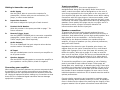
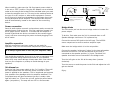
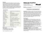
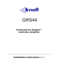
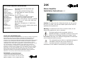
21K Stereo amplifier specifications
Inputs:
Gold RCA jacks with adjustable gain
Input impedance:
50k ohms
Outputs:
5 way gold insulated binding posts
Output power:
90 watts RMS per channel (8 ohms)
Ideal impedance:
4 – 8 ohms
Frequency response: 10 Hz – 40 kHz +/- 1dB
S/N ratio:
Over 106 dB A weighted (90 watts)
THD distortion:
Less than 0.1% 20 Hz to 20 kHz
IMD distortion:
Less than 0.01% 60 Hz 7 kHz 4:1 (SMPTE)
Dimensions:
17” x 3.5” x 11.5” (432 x 89 x 292 mm)
Fan noise:
No fan needed
Power:
Maximum 320 watts at 117 VAC 60 Hz
Weight:
20 lbs
Construction:
Steel chassis, powder coated; glass epoxy
printed circuit boards
Rack version:
21k-Rack
Three Year Limited Warranty
Knoll Systems warrants 21K amplifiers sold in the USA or Canada by authorized
Knoll dealers to be free from defects in materials and workmanship. This
warranty extends for three full years from the date of purchase by the
consumer. Any products returned freight prepaid to Knoll Systems and found to
be defective by Knoll Systems within the warranty period will be repaired or
replaced at Knoll Systems option, at no charge. Knoll Systems will not be
responsible for the actual cost of installation or removal of the product, nor for
any consequential or incidental damages. Some states do not allow the
exclusion or limitation of incidental or consequential damages, so the above
limitation or exclusion may not apply to you. This warranty gives you specific
legal rights. You may have additional rights, which vary from state-to-state.
Knoll products sold outside of the USA and Canada may be covered by
warranties provided by an authorized Knoll distributor. Please contact the
distributor in the country that the Knoll product was purchased.
Knoll Systems www.knollsystems.com
145 Tyee Drive Point Roberts, WA 98281
12140 Horseshoe Way Richmond BC V7A 4V5
Telephone (604) 272 4555, Fax (604) 272 5595
Made in Canada, © 2005, All Rights Reserved
21K
Stereo Amplifier
Installation Instructions v1.1
Caution: To reduce the risk of electrical shock, do not remove
the cover (or back). No user serviceable parts inside. Refer to
qualified service personnel.
Warning: To reduce the risk of fire or electric shock, do not
expose this appliance to rain or moisture.
The lightning flash with arrowhead, within an
equilateral triangle, is intended to alert the user to the
presence of uninsulated “dangerous voltage” within
the products that may be of sufficient magnitude to constitute a
risk of electrical shock to persons.
The exclamation point within an equilateral triangle is
intended to alert the user to the presence of
important operation maintenance (servicing)
instructions in the literature accompanying the appliance.
Important Safety Instructions:
1) Read these instructions.
2) Keep these instructions.
3) Read all warnings.
4) Follow all instructions.
5) Do not use this apparatus near water.
6) Clean only with dry cloth.
7) Do not block any ventilation openings. Install in accordance with the
manufacturer’s instructions.
8) Do not install near any heat sources such as radiators, heat registers,
stoves, or other apparatus (including amplifiers) that produce heat.
9) Do not defeat the safety purpose of the polarized or grounding-type plug. A
polarized plug has two blades with one wider than the other. A grounding type
plug has two blades and a third grounding prong. The wide blade or the third
prongs are provided for your safety. If the provided plug does not fit into your
outlet, consult an electrician for replacement of the obsolete outlet.
10) Protect the power cord from being walked on or pinched particularly at
plugs, convenience receptacles, and the point where they exit from the
apparatus.
11) Only use attachments/accessories specified by the manufacturer.
12) Use only with the cart, stand, tripod, bracket, or table specified by the
manufacturer, or sold with the apparatus. When a cart is used, use caution
when moving the cart/apparatus combination to avoid injury from tip-over.
13) Unplug this apparatus during lightning storms or when unused for long
periods of time.
14) Refer all servicing to qualified service personnel. Servicing is required
when the apparatus has been damaged in any way, such as power-supply
cord or plug is damaged, liquid has been spilled or objects have fallen into the
apparatus, the apparatus has been exposed to rain or moisture, does not
operate normally, or has been dropped.
15).Under no circumstances should the output terminals of the amplifier be
short-circuited.
16).Be sure that the loudspeakers connected can handle the output power of
the amplifier at the loudspeakers rated impedance. The warranty on the
amplifier does not cover damage to loudspeakers that have inadequate
power handling capabilities.
17) Where an all-pole MAINS SWITCH is used as the disconnect device, the
location on the apparatus and the function of the switch shall be described,
and the switch shall remain readily operable;
18) A push button is used to turn the power off and on.
19) A LED is used to show when the apparatus is powered on.
CAUTION: These servicing instructions are for use by qualified service
personnel only. To reduce the risk of electric shock do not perform any
servicing other than that contained in the operating instructions unless you
are qualified to do so.
Suggestion #3
Poor grounding of the electrical system in your home may also
cause ground loop problems, particularly when there are
multiple components with three prong, grounded, power cords.
Unplug these components one at a time, and see if one or all of
them is causing the problem. The ultimate solution to this type
of problem is to rewire your house with an isolated, star typegrounding configuration. Knoll understands that this may be
impractical and expensive. In some instances, the use of an
approved AC Power Isolation Transformer (Knoll model PLB200)
of sufficient capacity may solve this problem.
Warning: If you suspect that the grounding system in your
home’s electrical wiring is causing the hum problem, it is
important that you do not make any changes to the wiring. Only
a licensed electrician should make any changes to household
wiring, and they must be made in full compliance with all local
building, safety and electrical codes.
Suggestion #4
Faulty earth grounds may also cause hum in your home’s
electrical system. In the past, cold water pipes were often used
for the earth ground, so it is important to make sure that your
ground connection is working properly and has not become
loose or corroded. The cold water pipe method may no longer
be valid in some areas due to requirements that the water
meter be isolated for the water mains with a length of PVC pipe,
therefore interrupting the ground circuit. The safest and most
reliable approach may be to provide your own ground. This can
be accomplished by having a licensed electrician drive at least
five feet of copper-jacketed steel grounding rod into the earth,
and using that for your grounding connection. If the hum
persists after all of the above suggestions have been tried,
contact Knoll’s Technical Support department for assistance.
Do not use this amplifier near water including near a bathtub,
swimming pool or hot tub.
This unit should be installed so that its location does not
interfere with proper ventilation. For example, don’t place the
amplifier on a bed, sofa, rug, or similar surface that may block
the ventilation openings; or place in a built-in installation such
as a bookcase or cabinet that may block the flow of air through
its ventilation openings.
The unit should be set away from heat sources such as
radiators, heat vents, or other devices (including amplifiers)
that produce heat.
The unit should be connected to a power supply outlet only of
the voltage and frequency marked on its rear panel.
The power supply cord of the unit should be unplugged from the
wall outlet when it is to be unused for a long period of time.
Care should be taken so that objects to not fall, and liquids are
not spilled, into the enclosure through any openings.
The unit should be serviced by qualified service personnel when:
• The power cord or plug has been damaged; or objects
have fallen, or liquid has been spilled into the unit.
• The unit has been exposed to rain, or liquids of any kind;
or the unit does not appear to operate normally, or
exhibits a marked change in performance.
• The amplifier has been dropped, or the enclosure
damaged.
To prevent electric shock, do not use the polarized plug with an
extension cord, receptacle or other outlet unless the blades can
be fully inserted to prevent blade exposure.
Introduction: Thank you for your purchase of a Knoll 21K
stereo power amplifier and congratulations on your choice. This
amplifier is specifically designed to be the best sounding
amplifier available anywhere. Our engineers and designers
spent years of pain staking research and testing to perfect the
sound quality. We hope you will appreciate this effort and enjoy
the amp.
Unpacking: The carton and packing materials used in shipping
your new amplifier were specially designed to protect it from the
shock and vibration of shipping. We suggest that you save the
carton and packing materials to use if you move, or if the unit
ever needs to be shipped back to us for any reason. Should you
discover that your amplifier has been damaged during shipping,
please contact your dealer or Knoll immediately and request the
name of the carrier so a written claim can be made.
The right to a claim against a public carrier can be forfeited if the
carrier is not notified immediately in writing and if the shipping
carton and packing materials are not available for inspection by the
carrier. Save all packing materials until the claim is settled.
Placement
During normal home operation the amplifier will become warm.
However, there are instances during high-level playback into
low impedance speakers when the amplifier will become much
warmer than normal. To ensure the amplifier’s trouble-free
operation, it is necessary to provide adequate ventilation. Your
amplifier should be kept away from external sources of heat
such as radiators and hot- air ducts. The amplifier should never
be placed with other heat-producing components in a cabinet or
enclosure lacking free airflow. Do not stack other components
on top of your amplifier.
Rack mounting
A rack mount version of the 21K is available. For best operation
when rack mounting the 21k we suggest it be near the top of
the rack and have vented blank 1 rack space panels above and
below the 21k. For multiple 21k amps in one rack we suggest
spacing the amps 1 rack space apart and inserting a vented
blank 1-rack space panel between each amp.
Hum and noise
Troubleshooting
In most cases, one of the following suggestions should help you
solve a hum noise in your system. Please try these steps in the
order shown; proceeding from one step to the next if the prior
suggestion does not eliminate the problem.
Your Knoll amplifier is designed from trouble-free operation. If
you follow the instructions in this manual, you should enjoy
many years of high-quality listening enjoyment. However, as
with any sophisticated device, there may be occasional
problems upon initial installation, or during the life of the amp.
The items on the list below are a brief guide to the minor
problems that you may be able to correct yourself. If these
solutions do not help, or if the problem persists, contact us for
assistance.
Potential ground loops in a complex A/V system
Suggestion #1
To determine if a cable TV connection is responsible for the
hum, first turn off all the components. Disconnect the cable TV
feed to your system at the first place where it connects to your
components. Alternatively, disconnect the cable TV wire where it
is connected at the wall outlet. Turn your system back on, and
listen if the hum has disappeared. If removing the cable TV feed
has eliminated the hum, you will need to insert a Ground Loop
Isolator our model GB634) before reconnecting the cable TV
feed, or contact your cable TV operator to see if they can better
isolate your cable feed.
Suggestion #2
Turn off all components in your system, and then disconnect the
input cables at the amplifier. Turn the amplifier back on to see if
the hum is still present. If the hum disappears, the fault may be
in the input cables used. Try replacing them with cables that
have better shielding, and make certain that the input cables
are not running on top of any AC power cords. Change the
cables one at a time to determine if one or all cables are
responsive. If the hum disappears when the input cables are
disconnected, but returns after the cables are changed and the
system reconnected, your source device may be causing the
problem.
Problem
Solutions
Amplifier won’t turn on
Master power switch turned off (No
power light LED). Turn on Master Power
Switch.
Amplifier won’t turn off
Remote trigger cable not properly
connected. Verify connection of trigger
cable at both ends.
Amplifier turns on, but no
audio from one or more
channels
Input plugs not connected to proper
jack or are loose. Check input
connections.
No audio from one or more
channels
Speakers are not connected
properly. Check speaker connections at
amp and speaker.
Audio levels differ
from source device.
Improper settings or output levels
Check the settings on your preamp,
processor or controller. Also verify
settings of the rear panel gain controls
on your amp.
Audio plays and then cuts off
Amplifier may be shorted. Check
speaker connections for short-circuit at
amp and speaker.
Input connections
Getting to know the rear panel
A.
Audio Inputs
Use the INPUT jacks to connect the outputs of a
preamplifier, receiver with pre-out connections, CD
player, or other control devices.
B.
Input Gain Controls
Use these to adjust the input gain of each channel.
C.
Product Serial Number
Write this number in the space provided on page “” for
future reference.
D.
Remote Trigger Input
Use the REMOTE TRIGGER jack to connect a compatible
preamplifier, source device, or other product with a
12VDC output (abut 35mA required).
E.
Audio Outputs
This is an unbuffered line level output to other devices
such as another 21k amplifier.
F.
AC Input
Use the included power cord to connect your amplifier to
an AC power source.
G.
Speaker Outputs
Use the OUTPUT binding posts to connect the amplifier to
your speakers: red for positive, black for negative.
Connecting your amplifier
When making connections between any source components and
the amplifier, or when making connections to any speaker, be
certain that both the input devices and the amplifier are turned
off. Unplug all equipment before making any connections so that
there will be no unwanted signal transients that can damage
equipment or speakers.
Connecting the 21K to your source equipment is
straightforward. Using the high-quality audio interconnect
cables, match the output channel designations on the rear of
your source equipment to the input jacks on the rear panel of
your amplifier that have the same channel name. When making
connections with RCA type plugs on interconnect cables, make
certain to gently, but firmly, insert the plug into the jack. Loose
connections can cause intermittent sound and may damage your
speakers. Some quality RCA plugs may be very tight, and it is
important to secure a proper connection between the
interconnection cable and the input jack.
Speaker connections
To ensure that the high quality signals produced by your
amplifier are carried to your speakers without loss of clarity or
resolution, Knoll advises that you use high-quality speaker wire.
Many brands of wire are available — the choice may be
influenced by the distance between your speakers and the
amplifier, the type of speakers you use, personal preferences,
along with other factors.
Regardless of the brand or type of speaker wire chosen, we
suggest that you use a wire constructed of fine, multi-strand
copper with a gauge of 14 or less (the lower the number, the
thicker the cable). Wire with a gauge of 16 may be used for
short runs of less than 12 feet. We do not recommend that you
use any wires with an AWG equivalent of 18 or higher due to
the power loss and degradation in performance that will occur.
To connect the amplifiers to your speakers, a pair of binding
posts is provided for each channel output. These posts will
accept bare wire, spade lugs, or banana type plugs. If bare wire
is used for the connections, strip approximately 1/2 inch to 3/4
inch of insulation from the end of each wire and carefully twist
the strands of each conductor together. Be sure not to cut the
individual strands or twist them off. All strands must be used for
optimal performance.
Correct polarity connections are important to maintain proper
speaker phasing. When speaker phasing is correct, all speakers
move in and out at the same time preserving the imaging of the
program material. Out-of-phase connections mean that some
turn off, check your speakers to verify that they are operating
properly. If all other potential sources of trouble check out
properly, contact Knoll for further assistance.
Knoll Systems service information
The 21K amplifier does not contain any user serviceable parts
inside. If you suspect a problem that may require servicing,
contact us at www.knollsystems.com/contact.html, or by phone
at 800 566-5579. It is extremely important that only an
authorized service dealer make any repairs. This will ensure
proper service and preserve the protection of your warranty.
Keep your receipt in a safe place so that it will be available to
verify the purchase date, should you experience a problem
covered by Knoll System’s warranty.
Care, maintenance, and cleaning
When the 21k amp becomes dirty, wipe it with a clean, dry, soft
cloth. If necessary, first wipe the surface with a slightly
dampened soft cloth with mild soapy water, then with a fresh
cloth dampened with clean water. Wipe dry immediately with a
dry cloth. NEVER use benzene, thinner, alcohol, or any other
volatile cleaning agent. Do not use abrasive cleaners, as they
will damage the finish of the metal parts. Avoid spraying
insecticide, waxes, polishing agents, or any aerosol product near
the 21K.
21k Automatic on
Make certain that the connection to the controlling device is
correct. Whenever the controlling device is turned on, the
amplifier will automatically turn on after a short pause. This
pause is intentional and it protects your speakers from damage
while the amplifier stabilizes. You may also hear a relay click
during start up. This is also normal.
To turn off your amplifier, just turn off the device feeding the
amplifier its audio signals. The amplifier will automatically turn
off, which takes a few moments.
Gain controls
Level adjustments may be made at the rear of the amplifier.
The circuitry in your new amplifier may be different from your
previous one. Check the output levels to make sure that the
control device amplifier and speakers are properly matched.
Adjust these controls carefully as they operate in conjunction
with the volume control(s) on your source device. Turn down
the volume control(s) on the source device before adjusting the
controls on the amplifier.
AC line connector and power cord
Warning: Under no circumstances should the round third prong on the plug
be cut, bent or in any other way defeated as this may result in severe shock.
Always turn off the amplifier and unplug the power cord before making any
electrical connections.
Protection circuitry
Your Knoll amplifier uses an advanced protection circuit. The
output will be cut off if excessive low frequency (below 10 Hz) is
present, if the amp over heats or has excessive current
demands. The amplifier will begin to operate normally after the
over heating or excessive low frequency. Should this occur,
check all speaker wire connections, both at the speaker
terminals on the back of the amplifier to make certain that none
of the strands from any channel touch another channel, and that
none of the strands from a “positive” terminal touch strands
from a “negative” terminal. Even a few stray wires can cause
the amplifier to go into the protection mode. After checking all
speaker connections, turn the unit back on. If it continues to
speaker cones will be moving in, while others move out. This
will cause indistinct or confusing imaging, and muddled and
cloudy sounds. To avoid incorrect phasing or polarity, be sure to
use wire that has distinct markings, colors, stripes, wording, or
grooves on each side of the speaker cable. When making
connections to the amp and speakers, follow a consistent
pattern of using one side of the wire to the red terminals and
the other side to the black. When using cable with markings on
one side only, standard convention is to consider the marked
side of the wire as the red, or positive (+) connection, and the
non-marked side as the black or negative (-) connection.
Next loosen the knobs of the amplifier’s speaker output
terminals far enough so that they pass through hole is revealed.
Follow the proper connection instruction for your system with
regard to which terminals are used. Once the connections are
made, twist the cap back so that the connection is secured but
do not over tighten or use tools, as this may break the delicate
wire strands and decrease system performance.
If you are using spade lugs, connect them to the speaker wire
using the manufacturer’s instructions, and then loosen the caps
on the speaker terminals. Place lugs between the plastic cap
and the back of the terminal. Be sure to observe proper polarity.
Use your fingers to tighten to obtain a positive contact.
When using banana plugs, connections may be made by
inserting the jack affixed to your speaker wire into the hole
provided on the rear of the colored screw caps on the binding
posts. Before using banana –type jacks, make certain that the
plastic screw caps are firmly tightened down by turning them in
a clockwise direction until they are snug against the chassis.
This ensures that the maximum surface area of the plug is in
contact with the jack. Watch for proper polarity.
Run the cables to speaker locations. Do not coil any excess
cable, as this may become an inductor that creates frequency
response variations in your system. Lastly, connect the wires to
the speakers, again being aware of proper polarity. Remember
to connect the negative, or black wire, to the matching terminal
on the speaker. The positive or red wire should be connected to
the matching terminal on the speaker.
Note: While most speaker manufacturers follow industry convention of using
red terminals for positive connections and black terminals for negative, some
manufacturers may vary from this configuration. To ensure proper phase
connections, and optimal performance, consult the identification plate on our
speaker terminals, or the speaker’s manual to verify polarity. Contact the
speaker’s manufacturer if you do not know the polarity of your speakers.
Making rear panel connections
When connecting the amplifier to your source equipment, match
the output channel designations on the rear of your source
equipment to the input jacks on the rear panel of your amplifier
that have the same channel name. Correct polarity connections
are important to maintain proper speaker phasing. When
making connections to the amp and speakers, follow a
consistent pattern of using one side of the wire to the red
terminals and the other side to the black terminals.
Power control connections
The 21k amplifier features a built-in remote turn-on system that
can automatically switch the amplifier on when another device
in the system is switched on.
Remote turn-on using products equipped with a lowvoltage trigger jack: Make sure the 21k front panel power
switch is in the out of “OFF” position. Use an accessory cable
with a 3.5mm mono mini-plug on each end to connect the
trigger output jack on the rear of the source device to the
trigger input jack on the back panel of the amplifier. The trigger
needs to be 12 VDC and about 35 mA. When trigger power is
switched on, the amplifier will automatically turn on at the same
time.
Remote turn-on using external AC to DC power converter:
If your source device does not have a dedicated trigger jack, it
is still possible to activate the unit for automatic turn on when a
Switched Outlet is available on the rear of the source device. To
control the 21k amplifier this way, you will need a small AC to
DC power converter like our PS1202, capable of delivering 12
volts DC and over 35 mA. The DC voltage should terminate in a
standard 3.5mm type mini plug (this will have to be added to
the PS1202). This type of converter may be obtained as a power
adapter from many electronic retailers.
When installing, make sure the 21k front panel power switch is
in the out or “OFF” position. Plug the DC adapter into a switched
outlet on the source device that will be activated when you want
to have the amplifier turn on. This may be the switched outlet at
the rear of an AC receiver or other audio equipment. Connect
the 3.5mm mini-plug from the adapter to the trigger-input jack
on the back panel of the amplifier. The amplifier now turns on
and off automatically, based on the status of the controlling
device.
Power connection
Once all audio system connections have been made, connect the
supplied power cord to the amplifier first, and then connect it to
an AC power source. Please make certain that the amplifier is
turned off and that the device connected to the remote trigger
input is off when connecting the power cord and plugging it into
an AC outlet.
IN
+
O UT
Speakers
R
BRI DGE Ga in
(OU T)
1 2 VDC 45 mA
Tri gg er In put
Le ft
L
21K
R ight
L R
High Current
Power Amplifier
Power
8 A
12 0 VAC
~ 6 0 Hz
2-16 OHM
SPEAK ERS
Power
connection.
Observe
correct
voltage.
Bridge switch must be in OUT postion.
S OURC E
Connect speakers to RED terminals.
Minimum speaker impedance is
six (6) ohms.
+
-
Bridge Mode
The 21K can be put into the mono bridge mode to increase the
power output.
To do this, first make sure the 21K is powered down or off.
Speaker damage could occur if it is powered up.
Amplifier operation
Connect the source RCA jack to the left input. The left RCA
source output can be sent to another amplifier input.
After all connections have been made you are ready for
operation. First, turn on the source component in your system.
Make sure the bridge switch is in the out position.
It is always a good idea to turn on your amplifier LAST.
This avoids the possibility of any turn on pops or transients from
other equipment being amplified and sent to your speakers
where they may cause damage. Always start with a low volume
level on your computer or preamp to avoid damage to your
speakers.
21k Manual on
Press the 21k front power switch to the “on” position. There will
be a short pause from the time the power is turned on until
power is applied to the speakers. This is intentional and protects
your speakers from damage while the amplifier stabilizes. The
red protect lamp will glow and when the amp is ready a blue
light will switch on. To turn the unit off, press the power button
again (out position). The amp will turn off in a few seconds.
Connect the speaker (minimum 6 ohms) to the two red speaker
terminals on the 21K. The left red terminal on the 21K is
connected to the speaker positive (+) input. The black 21K
speaker terminals are not connected in the bridge mode.
Turn the Left gain on the 21k all the way down (counter
clockwise).
Turn the source on and the power to the 21k and adjust the Left
gain as desired.
Enjoy.