1
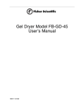
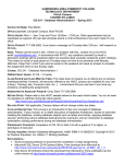
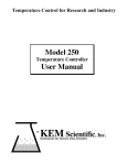
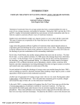
Imperial III General Purpose
Incubators
Series 1464, 1465, 1466
Model No.
Gravity Convection:
302, 302-1
305, 305-1
310, 310-1
Mechanical Convection:
305M, 305M-1
310M, 310M-1
LT1465X3 • 3/14/06
Table of Contents
Description ..........................................................................................................................................................3
Safety Information ..............................................................................................................................................4
Alert Signals..................................................................................................................................................4
Specifications ......................................................................................................................................................5
Electrical Requirements................................................................................................................................5
Temperature Range ......................................................................................................................................5
Shipping Weight............................................................................................................................................5
Unit Dimensions............................................................................................................................................5
Environmental Conditions ............................................................................................................................6
Unpacking and Installation ..................................................................................................................................7
Shipping Carton ............................................................................................................................................7
Location ........................................................................................................................................................7
Leveling ........................................................................................................................................................7
Shelf Installation ..........................................................................................................................................7
Operation ............................................................................................................................................................9
Control Panel ................................................................................................................................................9
Start-Up ........................................................................................................................................................9
Setting Operating Temperature Thermostat ..............................................................................................10
Temperature Controller ..............................................................................................................................10
Auto Tune....................................................................................................................................................11
Temperature Calibration ............................................................................................................................12
Troubleshooting ................................................................................................................................................14
Maintenance......................................................................................................................................................15
Checking Controls ......................................................................................................................................15
Cleaning......................................................................................................................................................15
Care and Cleaning of Stainless Steel ........................................................................................................15
The Alloy Called Stainless ..........................................................................................................................15
Stainless Guidelines ..................................................................................................................................16
The pH Factor ............................................................................................................................................16
Special Considerations ..............................................................................................................................17
Cleansing Agents........................................................................................................................................17
Cleaning Methods ................................................................................................................................17
Materials Effective in Disinfecting ........................................................................................................18
Servicing Guide ................................................................................................................................................19
Heater Replacement ..................................................................................................................................19
Thermostat Replacement ..........................................................................................................................19
Switch or Status Lamp Replacement ........................................................................................................19
Replacing Temperature Controller ..............................................................................................................20
Replacement Parts............................................................................................................................................21
Wiring Diagram..................................................................................................................................................22
Ordering Procedures ........................................................................................................................................24
Decontamination Statement ..............................................................................................................................25
Two Year Limited Warranty ..............................................................................................................................28
2
Description
Barnstead|Lab-Line Imperial III General Purpose
Incubators are useful in all types of general incubating
and paraffin imbedding.
Cabinets are made of heavy-gauge steel with a powdercoated finish for optimum appearance and easy cleaning,
while the interior walls are stainless steel to spread warmwall radiant heat evenly throughout the chamber. Heaters
are in direct contact with chamber walls to allow close
temperature control and quick recovery after door openings. This arrangement also minimizes temperature gradients and offers a large working area in the chamber.
A double set of doors, the inner of tempered glass, permits unobstructed viewing of chamber contents without
disturbing the interior environment. Slide-out shelving
can be positioned to meet user requirements.
A PID microprocessor based controller maintains chamber temperature. An over-temperature safety thermostat
controls temperature in the event of primary control failure. A status lamp above each control is lit when the
respective control is maintaining power to the heaters.
Incubators are available in three sizes. A grounded 3prong convenience outlet is supplied in midsize model
chambers and 2 outlets are installed in larger models.
Models are built for either 120 VAC or 240 VAC power
requirements. Models 305M and 310M have the same
characteristics as those listed above but, in addition, provide mechanical convection. These models use a blower
and plenum design to circulates the air within the chamber that allows for rapid temperature and uniformity recovery after door openings.
Model 302
3
Safety Information
Alert Signals
Warning
Warnings alert you to a possibility of
personal injury.
Caution
Cautions alert you to a possibility of
damage to the equipment.
Note
Notes alert you to pertinent facts and
conditions.
Hot Surface
Hot surfaces alert you to a possibility of
personal injury if you come in contact
with a surface during use or for a period
of time after use.
4
Your Barnstead|Lab-Line Imperial III General Purpose
Incubator has been designed with function, reliability, and
safety in mind. It is your responsibility to install it in conformance with local electrical codes. It is most important
that the user follow installation instructions exactly as written. Failure to do so is likely to lead to improper operation, erroneous calibrations and possible damage to the
equipment. Do not attempt operation without this information.
Specifications
Electrical Requirements
Voltage
Hertz
Amps
Watts
302
120
50/60
2.1
400
302-1
240
50/60
0.7
400
305
120
50/60
3.3
400
(1 electrical outlet, 120V, 500W total load)
305M
120
50/60
3.7
400
(1 electrical outlet, 120V, 500W total load)
305-1
240
50/60
1.7
400
(1 electrical outlet, 120V, 500W total load)
305M-1
240
50/60
1.7
400
(1 electrical outlet, 120V, 500W total load)
310
120
50/60
5.0
600
(1 electrical outlet, 120V, 500W total load)
310M
120
50/60
5.8
600
(1 electrical outlet, 120V, 500W total load)
310-1
230/240
50/60
2.5
600
(1 electrical outlet, 120V, 500W total load)
310M-1
230/240
50/60
2.5
600
(1 electrical outlet, 120V, 500W total load)
Temperature Range
Slightly above ambient to 65°C
Shipping Weight
302 Models:
305 Models:
310 Models:
75 lbs. (34 kg)
120 lbs. (55 kg)
215 lbs. (98 kg)
Unit Dimensions
INSIDE
13"W x 17"D x 20"H
(33 x 43 x 51 cm)
OUTSIDE
16"W x 21"D x 29.5"H
(41 x 53 x 75 cm)
305 Models:
17"W x 21"D x 25"H
(43 x 53 x 64 cm)
20"W x 25"D x 34.5"H
(51 x 64 x 88 cm)
310 Models:
37"W x 21"D x 25"H
(94 x 53 x 64 cm)
40.5"W x 25"D x 34.5"H
(103 x 64 x 88 cm)
USABLE VOLUME
SHELVES
SHELF AREA
302 Models:
2.6 cu. ft.
2
2.8 sq. ft.
305 Models:
5.2 cu. ft.
3
6.9 sq. ft.
310 Models:
11.2 cu. ft.
6
13.8 sq. ft.
302 Models:
5
SPECIFICATIONS
Environmental Conditions
Operating:
Storage:
6
15°C to 40°C; 20% to 80% relative humidity, non-condensing.
Installation category II (overvoltage) in accordance with IEC 664.
Pollution degree 2 in accordance with IEC 664.
Altitude Limit: 2,000 meters.
-25°C to 65°C
10% to 85% relative humidity
Unpacking and Installation
Shipping Carton
The shipping carton should be inspected upon delivery.
When received, carefully examine for any shipping damage before unpacking. If damage is discovered, the delivering carrier should both specify and sign for the damage
on your copy of the delivery receipt.
Open the carton carefully making certain that all parts are
accounted for before packaging materials are discarded.
After unpacking, if damage is found promptly report it to
the carrier and request a damage inspection promptly.
IMPORTANT: Failure to request an inspection of damage
within a few days after receipt of shipment absolves the
carrier from any liability for damage. You must call for a
damage inspection promptly.
Location
Place the unit on a level surface protected from drafts,
strong air currents and large fluctuations in ambient temperature. It must be located near an electrical outlet that
meets the unit nameplate requirements. Allow clearance
around the unit for free air convection, accessory equipment, and user convenience. Do not cover the vent on
top of the incubator.
Leveling
It is important that the unit is level before operation. DO
NOT REMOVE THE UNIT’S RUBBER FEET—they assist
proper air circulation inside and outside of the chamber.
Removal can result in erratic control and excessive heat
build-up beneath the unit.
Shelf Installation
1.
Each shelf bracket has 2 prongs at each end for
attachment to the chamber sidewall. Insert the
longer top prongs into slots of equal height on
one side of the chamber, then push the bracket
up and insert the lower prongs.
2.
Push down on the bracket to insure proper seating.
Note
Leave unit disconnected when not in
use.
7
UNPACKING AND INSTALLATION
8
3.
Repeat this procedure for the opposing bracket
making sure it is on the same level as the first
bracket (count the slots).
4.
Install other shelf brackets in the same way then
slide shelves into place.
Operation
Control Panel
1
2
Warning
Do not use in the presence of flammable or combustible materials or
explosive gases. Do not use in the
presence of pressurized or sealed
containers. Fire or explosion may
result, causing death or severe
injury.
Warning
Do not heat any substance above a
temperature that will cause it to emit
toxic fumes. Death or severe injury
may result.
3
4
5
1.
POWER SWITCH: This 2-position rocker switch
controls power to entire unit. The switch is lit
when power is ON.
2.
CONTROL STATUS LAMP: This lamp is lit when
power is being supplied to heater and not lit
when power to the heater is OFF.
3.
PROGRAMMABLE CONTROLLER: Maintains
chamber temperature and provides a display of
either chamber or set point temperatures.
4.
OVER-TEMPERATURE STATUS LAMP: This
lamp is lit when either an over-temperature condition exists or the over-temperature thermostat
is improperly set too low.
5.
OVER-TEMPERATURE THERMOSTAT: This
hydraulic thermostat is set by the operator to
back up the control thermostat and safeguard
the incubator.
Start-Up
Insert a flat-blade screwdriver into the panel opening and
rotate the over-temperature thermostat stem completely
clockwise. After making sure the unit is plugged in, press
the power switch to ON.
9
OPERATION
Setting the Over-Temperature
Thermostat
After the unit has reached set point, rotate the over-temperature thermostat stem counterclockwise until the overtemperature status lamp (4) is lit. Then rotate it clockwise
approximately 5 degrees past the point at which the lamp
is no longer lit. At this point, the over-temperature thermostat will control heaters only at temperatures above the
controller set point.
Temperature Controller
Chamber or Setpoint Temperature
Heat Indicator
65.0
✱
10
▼
▼
1.
CONTROLLER SELF-TEST: When the incubator is powered up the controller will display 8888
along with the three decimal points and the heat
ON indicator lamp. The display will then blank
out for 2 seconds before showing the chamber
temperature.
2.
HEAT ON INDICATOR: The heat ON indicator
lamp is lit when the chamber heater is receiving
power. The lamp will normally flash when the
chamber temperature is at set point.
OPERATION
3.
SET POINT ADJUSTMENTS: The temperature
controller normally displays the chamber temperature. To view or change the temperature
set point proceed as follows:
Press
✳
✳▼
✳▲
Controller
View setpoint
Decrease setpoint
Increase setpoint
A.
Press and hold the “STAR” (✳) key and use
either the UP or DOWN arrow key to adjust the
set point to the desired temperature. Release
the “STAR” (✳) key.
B.
Allow at least 30 minutes for the chamber temperature to stabilize.
Auto Tune
The auto tune program automatically adjusts the controller parameters to achieve optimal temperature control.
It is not necessary to run the auto tune program when
setting up the oven. However, if the temperature appears
to be unstable, the auto tune program can be run using
the procedure shown below:
For Best Results
•
Set the usual set point temperature and use normal load conditions.
•
Allow the oven to stabilize at set point for at
least 30 minutes.
Auto Tuning Procedure
1.
2.
Enter the program mode by pressing and holding BOTH the UP and DOWN arrow keys for 3
seconds.
Release BOTH arrow keys when tunE is displayed.
11
OPERATION
3.
The controller display should now be alternating
between tunE and oFF.
4.
Press and hold the “STAR” (✳) key. Press and
release the up arrow key until At.SP is displayed. Release the “STAR” (✳) key.
5.
After one minute has elapsed, the controller display will begin to alternate between showing the
chamber temperature, tunE and At.SP.
6.
Allow the program to run until the display again
shows only the chamber temperature.
Temperature Calibration
12
1.
Place a calibrated thermometer in the approximate geometric center of the chamber in a position that would allow it to be read through the
glass door.
2.
Press and hold the “STAR” (✳) key and using
the UP or DOWN arrow key, adjust the set point
to the desired temperature.
3.
Allow the unit to run for at least 30 minutes.
4.
The controller display should now be indicating
the set point temperature. Make note of the thermometer reading without opening the glass
door.
5.
Press and hold both arrow keys until the controller display indicates tunE. Release the
arrow keys. Press and release the down arrow
key, the display should now indicate LEUL.
Press and hold the “STAR” (✳) key and using
the UP arrow key adjust the display to read 3.
Release the “STAR” (✳) key. Press and release
the UP arrow key until the display indicates
Zero. The display should now alternate
between Zero and a numerical value.
OPERATION
6.
Thermometer
Controller Reading
Subtract
=
=
=
Using the examples shown below and the thermometer value obtained in the previous step,
enter the correct Zero value into the controller
by pressing the “STAR” (✳) key and using the
UP or DOWN arrow key. If there is already a
Zero value present then add the new value to
the one already present.
60°C
65°C
-5°C
Enter Zero value of -5°C
Thermometer
Controller Reading
Subtract
=
=
=
70°C
65°C
+5°C
Enter Zero value of +5°C
7.
When the correct Zero value has been entered,
press and hold the two arrow keys together until
the display again indicates the chamber temperature. If the procedure was done correctly, the
controller display should now agree with the
thermometer reading to within ±0.5ºC.
8.
Allow the unit to run for at least 30 minutes.
9.
Re-check the thermometer reading, the controller display and the thermometer should agree
to within ±0.5ºC. If not repeat steps 4, 5
and 6 above.
13
Troubleshooting
The following is intended as a guide to help in servicing this unit, if problems should occur.
Note
Before attempting any repair, disconnect power cord from outlet.
Note
A qualified controls service technician must perform maintenance and
repairs.
Symptom
Possible Causes of Problem
Power switch lamp is not lit when the
power switch is ON:
Check that unit is plugged in and that the plug is
good.
Press the power switch to OFF and then back ON. If
the lamp remains unlit, reset the back panel circuit
breaker(s) by pushing in the reset button(s).
Check the outlet to be sure power is available to the
unit.
Power switch lamp is the only one lit when
following the directions in the previous
OPERATION section:
Using a screwdriver rotate the over-temperature
thermostat stem completely clockwise (to highest
temperature settings). If unit still does not heat up,
the problem most likely involves the heater status
lamp. If the lamp is good, check the heaters and
heater wiring.
Convenience outlets are not powered
when unit is plugged in:
Check that the other features of the unit are
functioning. If not, proceed with the first step listed
above.
Remove any plugs from the convenience outlet(s).
Press in the circuit breakers (located on the back
panel) to reset. If the circuit breaker pops repeatedly,
check the equipment that is connected to the
convenience outlet; check wiring from circuit breaker
to the convenience outlet.
14
Maintenance
Warning
Disconnect from the power supply
prior to maintenance and servicing.
Warning
Refer servicing to qualified personnel.
Checking Controls
•
While using the unit, occasionally check that both
control panel status lamps are functioning as
described in the previous OPERATION section.
•
During normal operation, with controls properly set,
the over-temperature status lamp is not supposed to
be functioning. If it is and continues to be lit after recalibration as described in the previous OPERATION section, follow the procedures described in the
upcoming TROUBLESHOOTING section to locate
the source of the problem.
Cleaning
•
Clean any spills immediately. Use only soap or mild
detergent and water with a soft cloth for cleaning.
Do not use abrasives on the glass inner door. Refer
to following section for care of stainless steel surfaces.
•
Wipe exterior with soft damp cloth as necessary to
remove dust, fingerprints or other smudges.
Care and Cleaning of Stainless Steel
WARNING: Electrolysis can damage stainless steel. This
occurs when an object is allowed to rest directly on the surface of stainless steel, trapping moisture that becomes oxygen-starved, but is surrounded by water containing oxygen.
The Alloy Called Stainless
Stainless steel is an alloy of steel with chromium and nickel
that increase the metal’s resistance to rust and corrosion.
Yet, if not properly cared for, stainless steel can rust and corrode.
Exposure to air provides the passivation, or oxide layer coating, for clean stainless by producing a thin, durable chromium-oxide film that forms rapidly on the alloy surface to give
15
MAINTENANCE
stainless its characteristic “stainless” quality. Also exposure of the surface to other oxidizing environments can
produce a passivating film or coating.
However, if free oxygen is not available due to scale or
contamination buildup the metal surface may become vulnerable to rusting and corrosion as well as pitting. But by
maintaining neutral pH and conducting frequent cleanings
with detergent and water, years of trouble-free service
from stainless steel products can be obtained.
Stainless Guidelines
Distilled water is recommended. Please note, if this water
is very pure it may be corrosive to stainless. When filling
a bath or incubator, ALWAYS add 2 to 40 ppm (20 to 40
mg/liter) disodium phosphate or sodium bicarbonate,
adjusting dosage to provide a pH value of 7 to 9. If not
available, use clean, aerated soft tap water provided the
total solids concentration is < 500 PPM. We do NOT recommend using 18 meg-ohm deionized water. If this is the
only source of treated water available, mix with regular
tap water at a 50/50 ratio.
The pH Factor
Check pH regularly. If pH is <6.0, add disodium phosphate to increase pH to a 7 to 9 value. Sodium carbonate
or sodium bicarbonate may be used but they tend to form
scale that must be rinsed out regularly. If pH is >10.0,
add sodium bisulfate to decrease pH to a 7 to 9 value.
Avoid adding harsh alkalines or acids since these may
cause localized corrosion and result in unstable pH.
16
MAINTENANCE
Special Considerations
WARNING: If it is necessary to use the following chemicals, limit exposure time to a maximum of 3 hours.
Always clean surfaces immediately after use.
Aluminum chloride
Barium chloride
Calcium chloride
Chlorinated Lime
Citric acid (boiling)
Dakin’s solution
E.D.T.A.
Ferrous chloride
Lysol
Mercury salts
Phenol
Potassium permanganate
Potassium thiocyanate
Sodium hypochlorite
Stannous chloride
Tartaric acid
BE ADVISED: Never use the following on stainless steel:
Aqua regia
Ferric chloride
Iodine
Sodium acid
Sodium azide
Chemical spills, especially those agents listed here,
should be removed as soon as possible and the stainless
steel surface cleaned with mild soapy water followed by a
clean water rinse.
Cleansing Agents
Anti-fungal and anti-bacterial additives are permissible to
use as long as the pH of the aqueous solution is kept
within the range of 7 to 9. These are available through
laboratory distributors. Be sure to CONFIRM that they are
not harmful to stainless steel.
Do not use any metallic pads. Instead, for stubborn
stains, use a plastic light-duty cleansing pad and rub gently in the direction of the metal grain.
If stains continue to persist, use one of the following
chemicals and methods.
Note
The use and disposal of these
chemicals may be regulated by your
local city codes; consult those regulations before disposing of these
materials.
Cleaning Methods
CAUTION: Extreme care must be taken when handling
these materials. Always work in an area with adequate
ventilation. Use the precautions as outlined in the Material
Safety Data Sheet (MSDS) and the manufacturer’s
instructions for the product being utilized. Also, follow the
17
MAINTENANCE
personal protection index found in the hazardous materials information system (HMIS) section of the MSDS.
•
Any of a variety of “scale removers” available at
local supermarkets or hardware stores used for
the cleaning of coffee marks, humidifiers or
vaporizers.
•
A 15% to 35% phosphoric acid solution available from laboratory supply distributors for scale
and rust removal. Allow solution to soak the
surface affected until rust and scale is loosened.
Immediately follow with a clean water rinse.
•
Citric acid based cleaners.
•
Bathroom tub and tile cleaners.
•
A mixture of 20% nitric acid and 1.5% hydrofluoric acid (or hydrochloric acid). Swab solution on
surface allowing it to remain until rust is loosened. Immediately follow with a clean water
rise. This method should ONLY be used if
SEVERE rust and scale stains are present.
•
Oxalic acid 2% to 5% in warm water. Swab
solution on surface allowing it to remain until
rust is loosened. Immediately follow with a clean
water rinse. This method should ONLY be used
if SEVERE rust and scale stains are present.
Regardless of the approach utilized, ALWAYS follow the
manufacturer’s directions and allow the chemicals to do
the cleaning with MINIMAL scrubbing. Always follow
cleanings with a clean water rinse. Air dry.
Note
This information is intended as guidelines only and Barnstead International
makes no claim as to the suitability to
any particular situation. Consult your
staff chemist to determine what would
be best for your stainless steel product and laboratory.
18
Materials Effective in Disinfecting
•
Glutaraldehyde
•
Alcohol
Servicing Guide
Warning
Disconnect from the power supply
prior to maintenance and servicing.
Warning
Refer servicing to qualified personnel.
Heater Replacement
Heaters are not replaceable. Call Barnstead International
Customer Service at 1-800-553-0039 for assistance.
Thermostat Replacement
1.
After unplugging the unit, remove the top cover of
the unit to reach control components. Expose 2
screws holding thermostat to the mounting bracket.
2.
After removing thermostat from control panel, disconnect wiring while noting where each lead attaches.
3.
Remove back cover of unit to reach thermostat bulb,
set in a bracket under the chamber floor.
4.
Slide the bulb out of the bracket and through the top
hole to completely remove the thermostat.
5.
Install new thermostat by reversing above procedure.
Switch or Status Lamp
Replacement
1.
Power switch and status lamps are snap-in mounting type. Unplug unit, remove top cover and disconnect leads after noting where each attaches.
2.
Push the switch out from the back. Slide the lamp
body sideways to remove lens.
3.
Reverse procedure to install new lamp.
4.
Press replacement switch in from the front of the
panel and then reconnect the leads as noted.
Switch is to be oriented so that the green lamp is
toward the top.
19
SERVICING GUIDE
Replacing Temperature
Controller
1.
Place ON/OFF switch in OFF position.
2.
Unplug incubator from outlet power supply.
3.
To remove controller from control housing:
a) Use both hands to firmly grip each side of the
controller bezel.
b) Press on the bezel side grips until the bezel
tabs release.
Note
PCB contacts at rear of controller fit
into contacts at rear of controller
housing.
c) Slowly pull controller from housing
4.
To install new, factory-configured controller:
a) Carefully slide new controller into controller
housing.
b)Press controller bezel into controller housing
until bezel tabs securely lock controller into
place.
20
5.
Plug incubator into outlet power supply.
6.
Place ON/OFF switch in ON position.
Replacement Parts
DESCRIPTION
Fan Blade, M Series:
Cordset:
PART NUMBER
160-136-00
470-105-00
Gasket, Body:
Models 302 Series:
Models 305 Series:
Models 310, 310-1(2):
530-186-00
530-182-00
530-182-00
Gasket, Outer Door:
Models 302 Series:
Models 305 Series:
Models 310, 310-1(2):
530-185-00
530-181-00
530-181-00
Inner Door, Tempered Glass:
Model 302:
Model 305 (2):
Model 310, 310-1 (2):
540-177-00
540-176-00
540-176-00
Motor, 305M, 305M-1, 310M, 310M-1, 310M-1CE:
Receptacle (120 V), Models 305, 310:
Receptacle (240 V), Models 305-1, 310-1:
MT1465X1
420-036-00
420-214-00
Shelves:
Models 302 & 302-1 (2):
Models 305, 305-1(3), 310 & 310-1(6):
810-353-01
810-352-01
DESCRIPTION
Status Lamp Base (2):
Status Lamp Lens (Amber):
Status Lamp Lens (Red):
Switch, Power, 120V:
Switch, Power, 240V:
Thermostat, Over-temperature:
Configured Temperature Controller:
RTD Temp. Sensor:
Circuit Breaker 5 Amps:
Circuit Breaker 10 Amps:
PART NUMBER
360-233-01
360-235-00
360-234-00
440-359-00
440-292-00
920-301-00
CN71X34
410-632-00
330-118-00
330-119-00
Wiring Diagrams:
Models 302, 305, 310, 305M, 310M:
Models 302-1, 305-1, 310-1, 305M-1, 310M-1:
LT1465X1
LT1465X1
21
Wiring Diagrams
AMBER LAMP
RED LAMP
HLP
HLL
BLK
CONTROLLER
CTR
HLT
1 2 3 4 5 6
PWS
8
BLU
RED
NOT USED ON
BK2
BK1
SSR
G
MTR
N
WHT
L
BLK
TPS
WHT
BLK
WHT
MODEL 310 ONLY
CHAMBER ELEMENTS
22
REF.
DESCRIPTION
BK1
BK2
PWS
MTR
TPS
CTR
HLP
HLL
HLT
SSR
RESETABLE FUSE
RESETABLE FUSE
POWER SWITCH
FAN MOTOR
TEMPERATURE SENSOR
CONTROLLER
AMBER LAMP
RED LAMP
HI-LIMIT THERMOSTAT
SOLID STATE RELAY
302
------------330-118-00
440-359-00
------------410-632-00
CN71X134
PL1365X1
PL1465X2
920-301-00
400-233-00
302M
-------------
MODEL NUMBERS
305
305M
330-119-00
440-359-00
MT1465X1
440-359-00
MT1465X1
CN71X134
PL1465X2
920-301-00
400-233-00
PL1365X1
PL1465X2
CN71X134
PL1465X2
920-301-00
400-233-00
310
330-119-00
330-118-00
440-359-00
------------410-632-00
CN71X134
PL1466X1
PL1465X2
920-301-00
400-233-00
310M
330-119-00
330-118-00
440-359-00
MT1466X1
410-632-00
CN71X134
PL1466X1
PL1465X2
920-301-00
400-233-00
WIRING DIAGRAMS
AMBER LAMP
RED LAMP
HLP
HLL
BLK
BK2
BK1
WHT
BLK
CONTROLLER
CTR
HLT
1 2 3 4
PWS
8
6
WHT
BLU
BLU
RED
L
BRN
G
L
NOT USED ON MODEL 302-1
BK3
BK4
MTR
TPS
BLK
WHT
MODEL 310-1 ONLY
REF.
DESCRIPTION
BK1
BK2
BK3
BK4
PWS
MTR
TPS
CTR
HLP
HLL
HLT
SSR
RESETABLE FUSE
RESETABLE FUSE
RESETABLE FUSE
RESETABLE FUSE
POWER SWITCH
FAN MOTOR
TEMPERATURE SENSOR
CONTROLLER
AMBER LAMP
RED LAMP
HI-LIMIT THERMOSTAT
SOLID STATE RELAY
302-1
330-118-00
330-118-00
------------440-359-00
410-632-00
CN71X134
400-233-00
MODEL NUMBERS
305-1
305M-1
330-118-00 330-118-00
330-118-00 330-118-00
330-125-00
330-125-00 330-125-00
440-359-00 440-359-00
MT1465X2
410-632-00 410-632-00
CN71X134 CN71X134 CN71X134
PL1365X1
PL1365X1
PL1465X2
PL1465X2
920-301-00
400-233-00 400-233-00
302M-1
330-118-00
310-1
330-118-00
330-118-00
330-125-00
330-125-00
440-359-00
------------410-632-00
CN71X134
PL1466X1
PL1465X2
920-301-00
400-233-00
310M-1
330-118-00
330-118-00
330-125-00
330-125-00
440-359-00
MT1466X2
410-632-00
CN71X134
PL1466X1
PL1465X2
920-301-00
400-233-00
23
Ordering Procedures
Please refer to the Specification Plate for the complete
model number, serial number, and series number when
requesting service, replacement parts or in any correspondence concerning this unit.
All parts listed herein may be ordered from the
Barnstead International dealer from whom you purchased this unit or can be obtained promptly from the
factory. When service or replacement parts are needed
we ask that you check first with your dealer. If the dealer
cannot handle your request, then contact our Customer
Service Department at 563-556-2241 or 800-553-0039.
Prior to returning any materials to Barnstead
International, please contact our Customer Service
Department for a “Return Goods Authorization” number
(RGA). Material Returned without an RGA number will
be returned.
24
Decontamination Statement
We cannot accept any product or component sent to
Barnstead International for repair or credit that is contaminated with or has been exposed to potentially infectious agents
or radioactive materials.
No product or component will be accepted without a "Return
Goods Authorization" (RGA) number.
25
26
27
Two Year Limited Warranty
BARNSTEAD INTERNATIONAL (“BARNSTEAD”) warrants that a product manufactured by Barnstead shall be
free of defects in materials and workmanship for two (2) year from the first to occur of (i) the date the product
is sold by BARNSTEAD or (ii) the date the product is purchased by the original retail customer (the
“Commencement Date”). Except as expressly stated above, BARNSTEAD MAKES NO OTHER WARRANTY,
EXPRESSED OR IMPLIED, WITH RESPECT TO THE PRODUCTS AND EXPRESSLY DISCLAIMS ANY AND
ALL WARRANTIES, INCLUDING BUT NOT LIMITED TO, WARRANTIES OF DESIGN, MERCHANT ABILITY
AND FITNESS FOR A PARTICULAR PURPOSE.
An authorized representative of BARNSTEAD must perform all warranty inspections. In the event of a defect
covered by BARNSTEAD’s warranty, BARNSTEAD shall, as its sole obligation and exclusive remedy, provide
free replacement parts to remedy the defective product. In addition, for products sold by BARNSTEAD within
the continental United States or Canada, BARNSTEAD shall provide provide free labor to repair the products
with the replacement parts, but only for a period of ninety (90) days from the Commencement Date.
BARNSTEAD’s warranty provided hereunder shall be null and void and without further force or effect if there
is any (i) repair made to the product by a party other than BARNSTEAD or its duly authorized service representative, (ii) misuse (including use inconsistent with written operating instructions for the product), mishandling, contamination, overheating, modification or alteration of the product by any customer or third party or
(iii) use of replacement parts that are obtained from a party who is not an authorized dealer of BARNSTEAD.
Heating elements, because of their susceptibility to overheating and contamination, must be returned to the
BARNSTEAD factory and if, upon inspection, it is concluded that failure is due to factors other than excessive
high temperature or contamination, BARNSTEAD will provide warranty replacement. As a condition to the
return of any product, or any constituent part thereof, to BARNSTEAD’s factory, it shall be sent prepaid and a
prior written authorization from BARNSTEAD assigning a Return Materials Number to the product or part shall
be obtained.
IN NO EVENT SHALL BARNSTEAD BE LIABLE TO ANY PARTY FOR ANY DIRECT, INDIRECT, SPECIAL,
INCIDENTAL, OR CONSEQUENTIAL DAMAGES, OR FOR ANY DAMAGES RESULTING FROM LOSS OF
USE OR PROFITS, ANTICIPATED OR OTHERWISE, ARISING OUT OF OR IN CONNECTION WITH THE
SALE, USE OR PERFORMANCE OF ANY PRODUCTS, WHETHER SUCH CLAIM IS BASED ON CONTRACT, TORT (INCLUDING NEGLIGENCE), ANY THEORY OF STRICT LIABILITY OR REGULATORY
ACTION.
The name of the authorized Barnstead International dealer nearest you may be obtained by calling
1-800-446-6060 (563-556-2241) or writing to:
2555 Kerper Boulevard
Dubuque, Iowa 52001-9918
Phone: 563-556-2241 or 800-553-0039
Fax: 563-589-0516
E-mail: [email protected]
www.barnstead.com
28