1
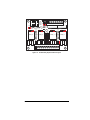
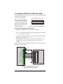
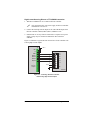
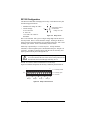
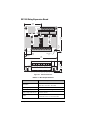
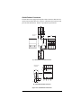
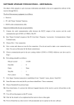
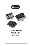
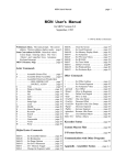
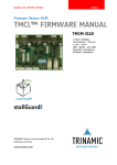
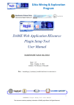
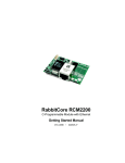
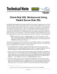
SE1100 Relay Output Boards Users Manual 0190050 010621A SE1100 Users Manual Part Number 019-0050 010621-A Printed in U.S.A. © 2001 Z-World, Inc. All rights reserved. Z-World reserves the right to make changes and improvements to its products without providing notice. Notice to Users Z-WORLD PRODUCTS ARE NOT AUTHORIZED FOR USE AS CRITICAL COMPONENTS IN LIFE-SUPPORT DEVICES OR SYSTEMS UNLESS A SPECIFIC WRITTEN AGREEMENT REGARDING SUCH INTENDED USE IS ENTERED INTO BETWEEN THE CUSTOMER AND Z-WORLD PRIOR TO USE. Life-support devices or systems are devices or systems intended for surgical implantation into the body or to sustain life, and whose failure to perform, when properly used in accordance with instructions for use provided in the labeling and users manual, can be reasonably expected to result in significant injury. No complex software or hardware system is perfect. Bugs are always present in a system of any size. In order to prevent danger to life or property, it is the responsibility of the system designer to incorporate redundant protective mechanisms appropriate to the risk involved. Trademarks ® Dynamic C is a registered trademark of Z-World ® Windows is a registered trademark of Microsoft Corporation PLCBus is a trademark of Z-World ® Hayes Smart Modem is a registered trademark of Hayes Microcomputer Products, Inc. Z-World, Inc. 2900 Spafford Street Davis, California 95616-6800 USA Telephone: Facsimile: Web Site: E-Mail: (530) 757-3737 (530) 753-5141 http://www.z w orld.com [email protected] SE1100 TABLE OF CONTENTS About This Manual v Chapter 1: Overview 9 Features ................................................................................................ 10 Chapter 2: Getting Started 13 Chapter 3: Software Reference 17 Appendix A: Specifications 19 Index 23 Connecting an SE1100 to a Z-World Controller .................................. 14 SE1100 Configuration ......................................................................... 16 SE1100 Relay Expansion Board .......................................................... 20 Quick-Release Connectors .............................................................. 21 Schematics Users Manual Table of Contents s iii iv s Table of Contents SE1100 ABOUT THIS MANUAL This manual provides instructions for designing a controller system that uses relay boards. Instructions are also provided for using Dynamic C® functions. Assumptions Assumptions are made regarding the user's knowledge and experience in the following areas: Ability to design and engineer the target system that is controlled by a controller with analog-to-digital conversion expansion boards. Understanding of the basics of operating a software program and editing files under Windows on a PC. Knowledge of the basics of C programming. $ The C Programming Language by Kernighan and Ritchie C: A Reference Manual by Harbison and Steel Knowledge of basic Z80 assembly language and architecture for controllers with a Z180 microprocessor. $ For a full treatment of C, refer to the following texts. For documentation from Zilog, refer to the following texts. Z180 MPU User's Manual Z180 Serial Communication Controllers Z80 Microprocessor Family User's Manual Knowledge of basic architecture for controllers with a Rabbit 2000 processor. $ For documentation from Rabbit Semiconductor, refer to the following texts. Rabbit 2000 Microprocessor Users Manual Rabbit 2000 Microprocessor Designers Handbook Users Manual About This Manual s v Acronyms Table 1 lists and defines the acronyms that may be used in this manual. Table 1. Acronyms Acronym Meaning EPROM Erasable Programmable Read-Only Memory EEPROM Electronically Erasable Programmable Read-Only Memory LCD Liquid Crystal Display LED Light-Emitting Diode NMI Nonmaskable Interrupt PIO Parallel Input/Output Circuit (Individually Programmable Input/Output) PRT Programmable Reload Timer RAM Random Access Memory RTC Real-Time Clock SIB Serial Interface Board SRAM Static Random Access Memory UART Universal Asynchronous Receiver Transmitter Icons Table 2 displays and defines icons that may be used in this manual. Table 2. Icons Icon $ ( Meaning Meaning Refer to or see ! Note Please contact 7LS Tip Caution FD Icon High Voltage Factory Default vi s About This Manual SE1100 Conventions Table 3 lists and defines the typographical conventions that may be used in this manual. Table 3. Typographical Conventions Example Description while Courier font (bold) indicates a program, a fragment of a program, or a Dynamic C keyword or phrase. // IN-01… Program comments are written in Courier font, plain face. Italics Indicates that something should be typed instead of the italicized words (e.g., in place of filename, type a file’s name). Edit Sans serif font (bold) signifies a menu or menu selection. ... An ellipsis indicates that (1) irrelevant program text is omitted for brevity or that (2) preceding program text may be repeated indefinitely. [ ] Brackets in a C function’s definition or program segment indicate that the enclosed directive is optional. < > Angle brackets occasionally enclose classes of terms. a | b | c A vertical bar indicates that a choice should be made from among the items listed. Pin Number 1 A black square indicates pin 1 of all headers. Pin 1 J1 Measurements All diagram and graphic measurements are in inches followed by millimeters enclosed in parenthesis. Users Manual About This Manual s vii viii s About This Manual SE1100 CHAPTER 1: OVERVIEW Chapter 1 gives an overview of the SE1100 relay board and its specific features. Users Manual Overview s 9 Z-Worlds SE1100 expansion boards provide a simple way to add relays to a control system built around a Z-World controller. These relay output boards can be connected to the digital outputs of any Z-World controller. The SE1100 adds expansion capability even to boards without a Z-World PLCBus interface. The SE1100s four SPDT relays are high-power relays. The relays are optically isolated, and have fuses and filters to protect them from noise and transients. Each relay has an LED indicator to help with system maintenance. Figure 1-1 illustrates a system of expansion boards mounted on a DIN rail and connected to a controller. Chapter 2, Getting Started, provides instructions and illustrations for connecting the SE1100 relay board to a controllers digital outputs. Features The SE1100 relay board is designed to interface to the digital outputs of any Z-World controller. The boards four relays have a 6.3 A fuse connected to the common pin for overcurrent protection. In addition to the fuses, a snubber circuit across the common and the normally open/ normally closed pins suppresses voltage spikes across the contacts. All of the signals from the four SPDT relays are brought out to header J1. The interface voltage has a range of 5 V to 24 V. A 24 V DC supply is needed to power the relays. When driving the relays with high-voltage drivers, an SE1100 can be located up to 15 m (50 feet) from the controller. The opto isolation between the controller and the relays provides an extra level of assurance to guard against noise from high-voltage transients. The LEDs on the relay board indicate the status of the relays. When an LED is on, the relay associated with that LED is energized. When an LED is off, the relay is in a default state. The default state is for the common terminal to be connected to the normally closed terminal. The onboard linear regulator provides the regulated +5 V to all the logic elements. The relays and the LEDs are driven with the unregulated DC input voltage. Altogether, the SE1100 draws approximately 80 mA from the DC power supply input when all the relays are turned on. 10 s Overview SE1100 H1 D1 U6 C19 R11 L3 R20 R12 R23 R22 J3 C20 R9 R10 L2 R19 U1 H.C.Driver L1 C18 U3 Opto R18 R24 R25 L0 Relay 1 R29 R30 Relay 0 R17 C17 R21 R13 Relay 3 R31 R32 Relay 2 R16 R33 R15 R28 R14 R27 R8 C7 F4 C8 R7 C5 F3 C6 R6 R4 R5 R3 R2 C3 F2 C4 R1 C1 F1 C2 Figure 1-2. SE1100 Relay Expansion Board Layout Users Manual Overview s 11 12 s Overview SE1100 CHAPTER 2: Users Manual GETTING STARTED Getting Started s 13 Connecting an SE1100 to a Z-World Controller DC GND 3 RET 2 2 REL2 REL1 1 REL3 REL0 The four relays are optically isolated from the digital outputs on the host controller. RET1 provides a return for REL0 and REL1; RET2 provides a return for REL2 and REL3. RET 1 Connect the SE1100 to the digital outputs of any Z-World controller through the quick-release connector J3. Figure 2-1 shows the pinout. 4 5 6 7 8 J3 Figure 2-1. J3 Screw Terminal Addresses High-Current Sinking Driver Connection 1. Wire RET1 and RET2 on J3 to K on the host controller. ! K is connected to the +DC power supply on the host controller. K should not exceed 25 V. 2. Connect the four high-current outputs from the host controller to REL0, REL1, REL2, and REL3 on J3. 3. GND and DC on J3 may either be connected to a separate 24 V power supply, or they may be connected to GND and +DC on the host controller.. Figure 8-2 illustrates a typical SE1100 connection to a host controller with sinking high-current outputs. J1 Controller +24 V +DC K J3 GND 1 RET 1 OUT-01 2 REL0 OUT-02 3 REL1 OUT-03 4 REL2 OUT-04 . . . Sinking Outputs 5 6 +24 V 7 8 REL3 RET 2 DC GND SE1100 Figure 2-2. Connecting SE1100 to Controller with Sinking High-Current Outputs 14 s Getting Started SE1100 High-Current Sourcing Drivers or TTL/CMOS Connection 1. Wire RET1 and RET2 on J3 to GND on the host controller. ! K is connected to the +DC power supply on the host controller. K should not exceed 25 V. 2. Connect the four high-current outputs or the TTL/CMOS outputs from the host controller to REL0, REL1, REL2, and REL3 on J3. 3. GND and DC on J3 may either be connected to a separate 24 V power supply, or they may be connected to GND and +DC on the host controller.. Figure 2-3 illustrates a typical SE1100 connection to a host controller with sourcing high-current outputs. J1 Controller +24 V +DC K J3 GND 1 RET 1 OUT-01 2 REL0 OUT-02 3 REL1 OUT-03 4 REL2 OUT-04 . . . Sourcing Outputs 5 6 +24 V 7 8 REL3 RET 2 DC GND SE1100 Figure 2-3. Connecting SE1100 to Controller with Sourcing High-Current Outputs Users Manual Getting Started s 15 SE1100 Configuration The SE1100 board holds four high-power relays. Each SE1100 relay has the following specifications: 3 2 Standard coil voltage 24 V DC. Contact ratings: 10 A at 24 V DC or 120 V AC, 7 A at 250 V AC resistive maximum. Configuration: SPDT Coil Actuation 1 Voltage: 24 V DC 4 5 Figure 2-4. Relay Circuit Pin 1 is the common. Pin 5 goes to a high-voltage/high-current driver on the relay board. Pin 2 is for the actuation voltage. Turning on the driver allows current to flow through the coil, switching on the relay. Pin 3 is the normally open contact. Pin 4 is the normally closed contact. Each relay is protected by a 6.3 A fuse on pin 1. To help eliminate transients, a resistor/capacitor pair is attached between pin 1 and pin 3 on each relay. An LED is connected in line with the coil on each relay, and lights up when current passes through the coil. Althought the relays are rated at 10 A, they are protected with 6.3 A fuses because the size of the traces on the printed circuit boards limits the current through each relay to 6 A. Header J1 is used to connect external devices to the relays. Figure 2-5 illustrates the pinouts for the relay connection pins on header J1. 1 12 C = normally closed O = normally open J1 M = common C O M C Relay 3 O M C Relay 2 O M C Relay 1 O M Relay 0 Figure 2-5. Relay Connection Pins 16 s Getting Started SE1100 CHAPTER 3: Users Manual SOFTWARE REFERENCE Software Reference s 17 There are no software drivers unique to the SE1100 expansion boards. Since the SE1100 is driven by the digital outputs of the host controller it is connected to, the drivers associated with the host controllers digital outputs will operate the relays on the SE1100. The following sample program shows how to use the SE1100 with Z-Worlds BL1700 controller. 17SE1100.C /* REL0 to U2, 0 REL1 to U2, 1 REL2 to U2, 2 REL3 to U2, 3 RET1 to RET2 to DC to BL1700, DCIN GND to U2, GND */ #use vdriver.lib #use eziobl17.lib main(){ unsigned long t; VDInit(); // hits watchdog periodically eioBrdInit(0); // initialize board while(1){ t = MS_TIMER; printf("on\n"); while((MS_TIMER – t) < 1000L){ outport(0x4100, 1); outport(0x4100, 3); outport(0x4100, 5); outport(0x4100, 7); } t = MS_TIMER; printf("off\n"); while((MS_TIMER – t) < 1000L){ outport(0x4100, 0); outport(0x4100, 2); outport(0x4100, 4); outport(0x4100, 6); } } } 18 s Software Reference SE1100 APPENDIX A: Users Manual SPECIFICATIONS Specifications s 19 SE1100 Relay Expansion Board 1.975 (72.0) (4.4) 0.175 typ 2.835 (50.2) 0.187 dia, 4x 0.825 (4.7) (21.0) 0.175 typ (4.4) 3.85 (33.5) ~1.32 ~1.17 (29.7) (97.8) Figure A-1. SE1100 Dimensions Table A-1. SE1100 Specifications Feature Specification Board Size 2.835" × 3.85" × 1.32" (72.0 mm × 97.8 mm × 33.5 mm) Operating Temperature –40°C to +70°C Humidity 5% to 95%, noncondensing Input Voltage and Current 24 V DC, 80 mA Relays 20 s Specifications 4 SPDT relays 6.3A at 250 V AC or 6.3A at 24 V DC SE1100 Quick-Release Connectors Dimensions in millimeters 2.5 5.0 The SE1100 comes equipped with quick-release connectors that allow for quick connection/disconnection. Figure A-2 illustrates the connectors and provides their dimensions. Table A-2 provides the specifications. 12.6 n x 5.0 15.5 26.0 5.8 6.3 (a) Quick-Release Female Connector Dimensions in millimeters 2.5 8.35 5.0 n × 5.0 3.9 3.85 3.5 12.0 1.0 (b) Quick-Release Male Connector Figure A-2. Quick-Release Connectors Users Manual Specifications s 21 Table A-2. Quick-Release Connectors Specifications Feature Specification Maximum Voltage, Current 15 A @ 300 V Insulation Resistance 100 GΩ Wire AWG #12–#26 stranded #14–#26 solid Stripping Length 310 inches Withdrawal Force Meets UL 486 Torque 7 inches per pound 22 s Specifications SE1100 INDEX B L board layout ............................... 11 LEDs .......................................... 10 C N coil voltage ................................ 16 connecting expansion boards14, 15 connection sinking driver ......................... 14 sourcing driver ....................... 15 connectors quick-release .......................... 21 contact ratings relays ...................................... 16 noise transients .......................... 10 D dimensions SE1100 ................................... 20 F features ....................................... 10 fuses ........................................... 16 H headers J1 ........................................... 16 J3 ........................................... 14 P pinout ......................................... 16 Q quick-release connectors ............ 21 R relay control .................................... 10 S sample programs 17SE1100.C ........................... 18 SE1100 ................................... 18 software SE1100 ................................... 18 specifications quick-release connectors ........ 22 relays ...................................... 16 SE1100 ................................... 20 I installation SE1100 expansion boards ...... 14 Users Manual Index s 23 24 s Index SE1100 SCHEMATICS Users Manual Schematics