1
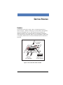
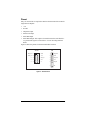
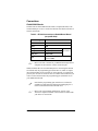
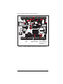
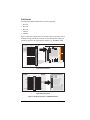
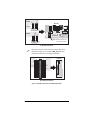
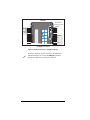
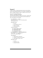
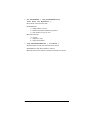
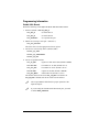
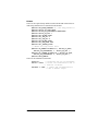
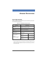
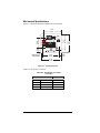
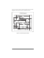
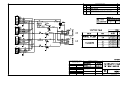
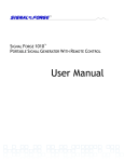
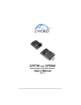
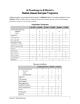
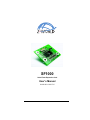
SF1000 Serial Flash Expansion Card Users Manual 0190102 011217C SF1000 Users Manual Part Number 019-0102 011217-C Printed in U.S.A. © 2001 Z-World, Inc. All rights reserved. Z-World reserves the right to make changes and improvements to its products without providing notice. Notice to Users Z-WORLD PRODUCTS ARE NOT AUTHORIZED FOR USE AS CRITICAL COMPONENTS IN LIFE-SUPPORT DEVICES OR SYSTEMS UNLESS A SPECIFIC WRITTEN AGREEMENT REGARDING SUCH INTENDED USE IS ENTERED INTO BETWEEN THE CUSTOMER AND Z-WORLD PRIOR TO USE. Life-support devices or systems are devices or systems intended for surgical implantation into the body or to sustain life, and whose failure to perform, when properly used in accordance with instructions for use provided in the labeling and users manual, can be reasonably expected to result in significant injury. No complex software or hardware system is perfect. Bugs are always present in a system of any size. In order to prevent danger to life or property, it is the responsibility of the system designer to incorporate redundant protective mechanisms appropriate to the risk involved. All Z-World products are 100 percent functionally tested. Additional testing may include visual quality control inspections or mechanical defects analyzer inspections. Specifications are based on characterization of tested sample units rather than testing over temperature and voltage of each unit. Z-World may qualify components to operate within a range of parameters that is different from the manufacturers recommended range. This strategy is believed to be more economical and effective. Additional testing or burn-in of an individual unit is available by special arrangement. Trademarks ® Dynamic C is a registered trademark of Z-World, Inc. PLCBus and Rabbit 2000 are trademarks of Z-World, Inc. Z80/Z180 is a trademark of Zilog Inc. Z-World, Inc. 2900 Spafford Street Davis, California 95616-6800 USA Telephone: Facsimile: Web Site: E-Mail: (530) 757-3737 (530) 757-3792 http://www.z w orld.com [email protected] SF1000 TABLE OF CONTENTS Introduction 5 Getting Started 7 Headers .................................................................................................. 7 Pinout ..................................................................................................... 8 Connections ........................................................................................... 9 Rabbit 2000 Boards .......................................................................... 9 Z180 Boards .................................................................................... 12 Software 15 Appendix. Specifications 21 Schematics 25 Dynamic C ........................................................................................... 16 SF1000.LIB Library Functions ....................................................... 16 Programming Information .................................................................... 18 Rabbit 2000 Boards ........................................................................ 18 BL2000 ......................................................................................... 19 Z180 Boards .................................................................................... 20 General Specifications ......................................................................... 21 Mechanical Specifications ................................................................... 22 Users Manual iii 4 SF1000 INTRODUCTION The SF1000 is a serial-interfaced flash memory card designed to work with Z-Worlds single-board computers. Single-board computers equipped with the Rabbit 2000 processor can use the SF1000 with either a synchronous serial peripheral interface (SPI) or an emulated SPI via parallel I/O ports. Zilog Z180-based single-board computers must use the emulated SPI method. Two SF1000 models are presently offered, as shown in Table 1. Table 1. SF1000 Models Model Flash Memory Size SF1000 8MB SF1010 4MB Larger memories will be possible in the future when parts become available. These serial flash cards are ideal for applications that require the temporary storage of large amounts of data. This data can be retrieved or downloaded to another system via the controlling single-board computer using TCP/IP or serial communication, or the card itself may be removed to facilitate transferring the data to another location. Users Manual 5 6 SF1000 GETTING STARTED Headers The SF1000 comes with a 10-pin, 2 mm, 5×2 header located at J1 as shown in Figure 1. Headers, either plugs or sockets, SMT or through-hole, may also be installed at J2 or J3. The pinouts for these positions are identical, and allow for a connecting cable to be hooked up in different ways. There is also a location at J4 for a 7-pin in-line header or socket with 0.1" spacing. Position 6 at J4 is not used, which allows this connection to be keyed. J1 5×2 header installed Flash EPROM J4 J3 J2 optional 5×2 headers optional 7×1 in-line header Figure 1. User Connection Points to SF1000 Users Manual 7 Pinout Only six connections are required to interface the SF1000 with a Z-World single-board computer: +5 V Ground Chip Select input Serial Clock Input Serial Data Input Serial Data Output. This output is inverted because the serial flash is a 3 V part and the signal is converted to 5 V via an inverting transistor buffer. Figure 2 shows the pinouts for the SF1000 header locations. J4 J1J3 SER_OUT 1 2 GND 1 SER_OUT SER_CLK 3 4 +5 V 2 GND n.c. 5 6 SER_IN 3 SER_CLK n.c. 7 8 /CS 4 +5 V n.c. 9 10 n.c. 5 SER_IN 7 /CS Figure 2. SF1000 Pinout 8 SF1000 Connections Rabbit 2000 Boards Serial Port B on all the Rabbit-based boards (except the BL2000) is the recommended port to use to connect the SF1000 serial flash card. Table 2 lists the connections. Table 2. SF1000 Connections to Rabbit-Based Board (except BL2000) SF1000 Signal +5 V Rabbit-Based Board +5 V GND GND SER_OUT PC5 (RXB) SER_IN PC4 (TXB) SER_CLK PB0 (CLKB) /CS user-selected output bit (default is PB7) $ Serial Port B Refer to the users manual for you Rabbit-based single-board computer for the locations of these connection pins. While Serial Port B is the recommended port for connecting the SF1000 serial flash card, the programming port (Serial Port A), which is compatible with the header pinout on header J1 on the SF1000, or a parallel I/O port may also be used. A connector cable is available from Z-World if you wish to connect the SF1000 to the programming port (Serial Port A) on your Rabbit-based board. ! Note that the programming port (Serial Port A) will not be available for application development and debugging if it is used to connect the SF1000 serial flash card. $ Refer to the Programming Information section of the Software chapter for details of the software associated with your choice of connections. Users Manual 9 A synchronous Serial Port B is not available on the BL2000, and so the following parallel-port connections are recommended instead. Table 3. SF1000 Connections to BL2000 SF1000 Signal BL2000 Board +5 V +5 V GND GND SER_OUT IN10 (PB5) SER_IN OUT3 (PA3) SER_CLK OUT2 (PA2) /CS OUT1 (PA1) Parallel Port A All three BL2000 outputs need to be pulled up to +5 V with a pull-up resistor of 1 kW to 2 kW. The following additional modifications need to be made. Remove R161 (removes GND from J9/J11 pin 12). Install R160 (adds VCC to J9/J11 pin 12). Remove C46, C47, and C48 (removes filter capacitors, which slow down the output signals). Remove C31 (removes filter capacitor, which slows down the input signals). 10 SF1000 Figure 3 shows the locations of these components. AGND + G BAD DS7 + Q5 DS6 Battery BT1 DS5 + DS4 + 10 C44 GND C45 C46 C47 C48 GND C49 GND C50 C51 GN D C52 Q6 DS8 C37 C42 GND DS3 Q3 1 K1 Q4 D DS2 R29 C32 R41 R42 R43 R44 R45 R46 R47 R48 R49 D4 D5 D6 D7 D8 D9 D10 D11 D12 C43 DS1 R26 R25 GND R21 6 GN D C12 5 GND C35 R38 R52 C40 R56 R60 GND C36 R39 R53 C41 R57 R61 C33 R36 R50 C38 R54 R58 J7 POWER IN 3 C26 R32 R34 R35 R40 D3 R33 C34 R37 R51 C39 R55 R59 3 R14 Q1 R24 C31 R31 L1 C77 1 2 U6 C29 4 40 TVS1 C25 C28 4 15 R151 Q2 R30 R22 C21 Y1 90 U4 C76 R152 U5 C9 U3 R18 65 Y2 C13 JP2 J12 C5 C7 PWR AGND R3 C15 C19 C22 R27 R28 C27 C24 GND C78 R17 R153 R154 U1 C18 C17 2 AG ND R2 R23 C14 Y3 1 AGND C75 R5 C79 C11 R11 R10 R157 JP1 C80 R130 R16 R15 R19 C16 D2 AGND C4 R7 C10R12 C23 D1 C2C3 AGND C8 U2 R8 R20 C20 J6 GND LNK R13C1 R9 ACT GND J5 AGND DAC1 DAC0 ADC8 ADC7 ADC6 ADC5 ADC4 ADC3 ADC2 ADC1 ADC0 OUT 0 GN D R4 R6 R1 J4 J3 485+ RXD2 TXD2 RXD1 TXD1 OUT 1 GND 485- OUT 2 IN0 OUT 3 IN1 S GND RST- + GND +K C85 +RAW GND J1 J2 GND GND GND J8 J10 J11 J9 IN2 IN3 IN4 IN5 IN6 IN7 IN8 C31 IN9 IN10 OUT8 OUT9 GND OUT0 OUT1 OUT2 OUT3 OUT4 OUT5 OUT6 OUT7 C46, C47, C48 NO COM NC GND R160 and R161 are on the opposite side of the board close to this corner. Figure 3. Locations of BL2000 Components to be Added or Removed Users Manual 11 Z180 Boards The following Z180-based boards are currently supported: BL1100 BL1500 BL1700 LP3100 PK2200 Figure 4 shows the connections to these boards. These connections may be modified as long as the library functions are also modified accordingly in the library specific to the single-board computer (e.g., EZIOBL17.LIB). SF1000 GND +5 V +5 V 1 /CS SER_CLK SER_IN SER_OUT PA0 1 PA1 3 PA2 5 PA3 7 PA4 BL1100 J010 J11 J6 J010 J30 J31 9 PA5 11 PA6 13 PA7 PB0 15 17 PB1 19 PB2 21 PB3 23 PB4 25 PB5 27 PB6 29 PB7 31 J10 J10 J9 J13 J8 J7 J18 J10 and J010 together constitute a single 34-pin connector. (a) BL1100 Connections BL1500 SF1000 26 25 DCIN 24 23 RS-485+ 22 21 VBAT GND 20 19 /RESET RTCDAT 18 17 RTCCLK P1B4 GND RS-485 GND /CS SER_OUT GND BL1500 SF1000 H3 16 15 P1B5 P1B6 14 13 P1B7 /ASTB 12 11 ARDY GND 10 9 P1A7 P1A6 8 7 P1A5 P1A4 6 5 P1A3 P1A2 4 3 P1A1 P1A0 2 1 +5 V SER_IN SER_CLK JP1 JP2 +5 V H3 (b) BL1500 Connections Figure 4. SF1000 Connections to Z180-Based Boards 12 SF1000 SER_OUT GND HVA03 HVA02 HVA01 HVA00 9 7 5 3 1 +5 V to Pin 2, Header J5 BL1700 (PLCBus) GND SF1000 BL1700 H9 H9 H10 H8 /CS SER_CLK SER_IN SF1000 GND HVB03 HVB02 HVB01 HVB00 9 7 5 3 1 Note: Remove capacitor C57 on back side of board. H10 (c) Bl1700 Connections ! Note that a capacitor must be removed on the BL1700 as indicated in Figure 4(c) to keep the SER_IN signal from getting slowed down too much by the capacitor. LP3100 SF1000 GND 1 2 +5 V 3 4 VBAK GND 5 6 DINOUT0 DINOUT1 7 8 DINOUT2 9 10 DINOUT4 DINOUT5 11 12 DINOUT6 DINOUT7 13 14 DOUT0 DOUT1 16 DOUT2 DOUT3 15 17 18 DOUT4 DOUT5 19 20 DOUT6 DOUT7 21 22 DIN0 DIN1 23 24 DIN2 DIN3 25 26 GND DINOUT3 SER_CLK SF1000 H2 DCIN VCCU RX0 27 28 TX0 TX1/RTS0 29 30 RX1/CTS0 RS-485 31 32 RS-485+ GND 33 34 VREF AIN1 35 36 AIN2 AIN3 37 38 AIN4 GND 39 40 /PB_RST LP3100 +5 V H1 /CS SER_IN SER_OUT H2 (d) LP3100 Connections Figure 4. SF1000 Connections to Z180-Based Boards Users Manual 13 PK2200 J1 Note: Remove capacitor bank CN2. J3 2 PIN01 GND GND /CS HV01 SER_CLK HV02 HV03 SER_IN 3 3 PIN02 4 PIN03 5 PIN04 6 PIN05 HV04 7 7 PIN06 HV05 8 8 PIN07 HV06 9 9 PIN08 HV07 10 10 +5 V F4 up down 6 del 5 CN1 4 CN2 GND 2 add 1 K 13 PIN11 14 14 PIN12 15 PIN13 F2 item HV11 SF1000 +5 V SER_OUT p HV10 F3 PIN10 13 12 run PIN09 11 HV09 field 11 12 HV08 nu SF1000 init 1 help +DC (e) PK2200 Connections Figure 4. SF1000 Connections to Z180-Based Boards ! 14 Note that a capacitor must be removed on the PK2200 as indicated in Figure 4(e) to keep the SER_IN signal from getting slowed down too much by the capacitor. SF1000 SOFTWARE The SF1000 serial flash expansion card implements a flash memory chip with a single, large, linear address space. It is up to the user to maintain appropriate information within the program in order to store and retrieve data in the flash memory. The flash memory chip consists of a series of sectors. The size of each sector is the same within a given chip, but can vary from one chip to another. A sector also contains extra bytes that are not made available to the user. Some of these bytes are used by the driver as follows: a fixed sync value, indicating that the sector has been written to at least once, a version number, and a long integer value for the number of times the sector has been written. The user should keep in mind that a flash memory chip has a limited number of write cycles per sector, and that an entire sector must be written at a time. The chips used in the SF1000 serial flash cards are specified at 50,000 write cycles typical. The most efficient usage dictates that the user block all writing to the flash memory so that only full sectors are written. More than one SF1000 serial flash card may be used in the control system built around the Z-World single-board computer. Users have to write their own CS_enable/CS_disable functions to control the chip select signals on the SF1000 serial flash cards. The only restriction is that all the SF1000 serial flash cards have the same size of flash memory chip, i.e., 4M or 8M. Users Manual 15 Dynamic C Z-Worlds Dynamic C integrated development software is used to add API functions from the SF1000.LIB library to your program. The SF1000.LIB library is available in Dynamic C Premier for Rabbit-based boards and in DC 32 for selected Z180-based boards. SF1000.LIB Library Functions The following API functions are available in the Dynamic C SF1000.LIB library. These functions are blocking functions, but do not disable interrupts. The functions are not re-entrant. int SF1000Init ( void ); Minimum setup needed to verify correct flash operation. PARAMETERS: None. RETURN VALUES: 0 = success -1 = invalid density value read -2 = unknown response -3 = maybe no SF1000? GLOBALS DEFINED: int int int int SF1000_Density_Value SF1000_Sector_size SF1000_Block_size SF1000_Nbr_of_Blocks int SF1000Write ( long FlashAddrDest, void* Data, int ByteCount ); Write a block of data to the flash. PARAMETERS: 1 = (long) address of destination 2 = (void*) source RAM starting address 3 = (int) number of bytes to write RETURN VALUES: 0 = success -1 = illegal byte count -2 = illegal flash address 16 SF1000 int SF1000Read ( long FlashAddrSource, void* Data, int ByteCount ); Read a block of data from the flash. PARAMETERS: 1 = (long) address of source 2 = (void*) destination RAM starting address 3 = (int) number of bytes to write RETURN VALUES: 0 = success -1 = illegal byte count -2 = illegal flash address long SF1000CheckWrites ( int Block ); Read the number of times that a block has been written. PARAMETER: (int) block number (0 relative) RETURN VALUE: the number of times the block has been written. Users Manual 17 Programming Information Rabbit 2000 Boards Define the following values before the #use SF1000.LIB statement. 1. Interface (default is SF1000_SER_B) SPI_SER_A use Serial Port A SPI_SER_B use Serial Port B SPI_PARALLEL use a parallel I/O port 2. SPI bit rate (if using a serial portdefault is 5) SPI_CLK_DIVISOR This is the divisor for the appropriate Timer A register. 3. I/O bit to be used for Chip Select (default is PB7) SF1000_CS_PORT SF1000_CS_PORTSHADOW SF1000_CS_BIT 4. I/O bits for parallel interface SPI_TX_REG register for clock and Tx data (default is PDDR) SPI_TXD_BIT bit number for Tx data (default is bit 1) SPI_CLK_BIT bit number for clock (default is bit 0) SPI_RX_REG register for Rx data (default is PDDR) SPI_RXD_MASK mask for Rx bit (default is 8, bit 3) The default values will be used if SPI_TX_REG is not defined. If SPI_TX_REG is defined, then all the values must be defined. 18 ! The I/O port must be initialized for proper operation of the input and output! ! If you are using the alternate Serial Port B I/O pins, you need to define SERB_USEPORTD. SF1000 BL2000 These are the required setup definitions when the BL2000 connections are made using Parallel Port A as described in this manual. #define #define #define #define #define #define #define #define #define #define SPI_MODE_PARALLEL 1 // show using parallel I/O SF1000_CS_PORT PADR SF1000_CS_PORTSHADOW PADRShadow SF1000_CS_BIT 1 SPI_TX_REG PADR SPI_TXD_BIT 3 SPI_CLK_BIT 2 SPI_RX_REG PBDR SPI_RXD_MASK 0x20 SPI_INVERT_CLOCK // define the chip select macro #define CS_ENABLE BitWrPortI ( SF1000_CS_PORT, &SF1000_CS_PORTSHADOW, 1, SF1000_CS_BIT ); #define CS_DISABLE BitWrPortI ( SF1000_CS_PORT, &SF1000_CS_PORTSHADOW, 0, SF1000_CS_BIT ); #define PROC_RABBIT These are the initialization statements. brdInit(); // initialize the I/O of the BL2000 SPIxor = 0xFF; // invert the received bits due to // inverter on SF1000 SPITXxor = 0xFF; // invert the transmitted bits // due to BL2000 output Users Manual 19 Z180 Boards The following Z180-based boards are currently supported. BL1100 BL1500 BL1700 LP3100 PK2200 Figure 3 in the Getting Started chapter shows the connections to these boards. These connections may be modified as long as the library functions are also modified accordingly in the library specific to the single-board computer (e.g., EZIOBL17.LIB). 20 SF1000 APPENDIX. SPECIFICATIONS General Specifications Table A-1 lists the electrical, mechanical, and environmental specifications for an SF1000 serial flash card. Table A-1. SF1000 General Specifications Parameter Board Size 1.51″ × 1.75″ × 0.25″ (38.4 mm × 44.5 mm × 6.4 mm) Operating Temperature −40°C to 70°C Humidity 5% to 95%, noncondensing Input Voltage and Current 4.75 V to 5.25 V DC, 60 mA maximum Flash Memory 8M (SF1000) 4M (SF1010) * Serial Data Rate Block size SF1000: 1024 bytes SF1010: 512 bytes * Specification BL1700 @ 18.4 MHz (SF1010) Read 70 ms/block Write 88 ms/block RCM2000 @ 25.8 MHz (SF1000) Read 14.0 ms/block Write 27.5 ms/block RCM2000 @ 25.8 MHz (SF1010) Read 7.3 ms/block Write 23.5 ms/block The BL1700 measurements were made using a "bit-banged" parallel I/O port to simulate an SPI; the RCM2000 measurements were made using a synchronous serial interface (SPI). Users Manual 21 Mechanical Specifications Figure A-1 shows the mechanical dimensions of an SF1000. 1.55 1.51 0.41 (10.4) Flash EPROM (38.4) 1.25 (31.8) 0.86 (21.9) (39.4) 0.22 1.34 (0,0) for Pin 1 coordinates (5.6) (34.0) 1.75 (44.5) Figure A-1. SF1000 Dimensions Table A-2 lists the pin 1 locations. Table A-2. SF1000 Pin 1 Locations (in inches) Header 22 Location J1 installed 0.551, 1.202 J2 not installed 1.267, 0.306 J3 not installed 0.485, 0.230 J4 not installed 1.102, 1.021 SF1000 Figure A-2 shows the footprint of another board that the SF1000 would be plugged into. These values are relative to the header connectors. SF1000 Footprint 1.324 J1 (33.6) 0.975 (24.8) 0.761 (19.3) 0.424 J4 (10.8) 1.343 1.010 0.942 (23.9) (34.1) 0.424 (25.7) (10.8) 0.147 0.259 (6.6) (3.7) 0.030 (0.8) J3 J2 0.046 (1.2) Figure A-2. User Board Footprint for SF1000 Users Manual 23 24 SF1000 SCHEMATICS Users Manual 25 REVISION APPROVAL REVISION HISTORY REV APPEND THE FOLLOWING DOCUMENTS WHEN CHANGING THIS DOCUMENT: PROJECT ENGINEER DESCRIPTION ECO APPROVAL DATE DOCUMENT CONTROL APPROVAL DATE DRAWING CONTENT: ZWORLD 2900 SPAFFORD ST. DAVIS, CA 95616 530 - 757 - 4616 APPROVALS: INITIAL RELEASE B SIGNATURES DATE NONE 26 SF1000