1
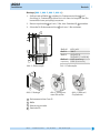
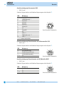
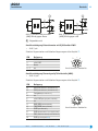
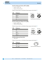
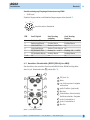
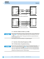
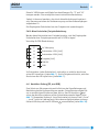
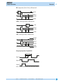
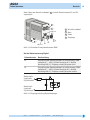
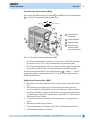
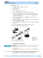
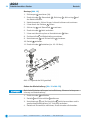
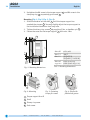
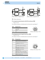
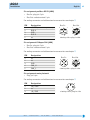
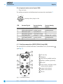
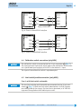
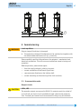
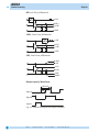
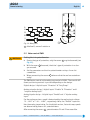
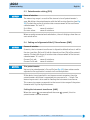
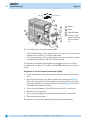
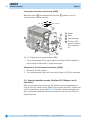
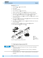
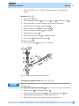
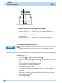
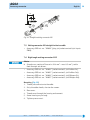
AG02 Stellantrieb Originalmontageanleitung DeutschSeite 2 Actuator Translation of the Original Installation Instructions Englishpage 33 277/14 2 AG02 Deutsch Inhaltsverzeichnis 1 Dokumentation ��������������������������������������� 2 Sicherheitshinweise ����������������������������������� 2.1 Bestimmungsgemäße Verwendung ��������������������� 2.2Kennzeichnung von Gefahren und Hinweisen ������������� 2.3Zielgruppe ����������������������������������������� 2.4Grundlegende Sicherheitshinweise ��������������������� 3 Identifikation 6 Transport, Lagerung, Wartung und Entsorgung ������������ 7 Zubehör Anschluss-Stecker ���������������������������� 7.1 Gegenstecker M16 gerade ���������������������������� 7.2Gegenstecker M16 gewinkelt ������������������������ 7.3Gegenstecker M9 gerade ���������������������������� 7.4Gegenstecker M9 inkl. Kabel ������������������������ 7.5Gegenstecker M12 gewinkelt ������������������������ 7.6Gegenstecker M12 BUS-Abschluss �������������������� 8 Technische Daten 9 Einbauerklärung 5 4 Installation ������������������������������������������� 4.1 Mechanische Montage ������������������������������� 4.2Elektrische Installation ����������������������������� 4.3Anschluss Schnittstelle (RS232/RS485/nur ABM) �������� 4.4Anschluss Kalibrierschalter (nur ABM) ���������������� 4.5Anschluss Endschalter/Freigabe (nur ABM) ������������ 4.6Anschluss Erdung (PE, nur ABM) ���������������������� 5 Inbetriebnahme �������������������������������������� 5.1 Geber Inkremental �������������������������������� 5.2Motorsteuerung PWM ������������������������������ 5.3Einrichtung Potentiometer (P10) ���������������������� 5.4Einstellen und Abgleich des R/I-Wandlers (MWI) �������� 5.5Einstellen und Abgleich des R/U-Wandlers (MWU) �������� 5.6Geber absolut magnetisch (Profibus-DP; CANopen; serielle Schnittstellen) ������������������������������������ 3 3 3 4 4 ����������������������������������������� 3 6 6 8 13 14 14 15 16 16 18 20 20 22 23 24 24 24 25 27 28 28 29 ������������������������������������ 29 �������������������������������������� 32 AG02 · Datum 22.07.2014 · Art. Nr. 82270 · Änd. Stand 277/14 AG02 DokumentationDeutsch 1 Dokumentation Zu diesem Produkt gibt es folgende Dokumente: • Datenblatt beschreibt die technischen Daten, die Abmaße, die Anschlussbelegungen, das Zubehör und den Bestellschlüssel. • Montageanleitung beschreibt die mechanische und die elektrische Montage mit allen sicherheitsrelevanten Bedingungen und der dazugehörigen technischen Vorgaben. • Benutzerhandbuch zur Inbetriebnahme und zum Einbinden des Stellantriebes in ein Feldbussystem. Diese Dokumente sind auch unter "http://www.siko-global.com/de-de/ service-downloads" zu finden. 2 Sicherheitshinweise 2.1 Bestimmungsgemäße Verwendung Der Stellantrieb AG02 dient für Verstell- und Positionieraufgaben an Anlagen und Maschinen. Der Stellantrieb ist nur für die Verwendung im Industriebereich vorgesehen die keinen besonderen elektrischen oder mechanischen Sicherheitsanforderungen unterliegen. 1. Beachten Sie alle Sicherheitshinweise in dieser Anleitung. 2. Lesen Sie alle beigefügten Dokumentationen auf der CD. 3. Eigenmächtige Umbauten und Veränderungen an dem Stellantrieb sind verboten. 4. Die vorgeschriebenen Betriebs- und Installationsbedingungen sind einzuhalten. 5. Der Stellantrieb darf nur innerhalb der technischen Daten und der angegebenen Grenzen betrieben werden (siehe Kapitel 8). 2.2 Kennzeichnung von Gefahren und Hinweisen Sicherheitshinweise bestehen aus dem Signalzeichen und einem Signalwort. Gefahrenklassen GEFAHR Unmittelbare Gefährdungen die zu schweren irreversiblen Körperverletzungen mit Todesfolge, Sachschäden oder ungeplanten Gerätereaktionen führen können, sofern Sie die gegebenen Anweisungen missachten. WARNUNG Gefährdungen die zu schweren Körperverletzungen, Sachschäden oder ungeplanten Gerätereaktionen führen können, sofern Sie die gegebenen Anweisungen missachten. AG02 · Datum 22.07.2014 · Art. Nr. 82270 · Änd. Stand 277/14 3 4 AG02 SicherheitshinweiseDeutsch VORSICHT ACHTUNG Gefährdungen die zu leichten Verletzungen, Sachschäden oder ungeplanten Gerätereaktionen führen können, sofern Sie die gegebenen Anweisungen missachten. Wichtige Betriebshinweise die die Bedienung erleichtern oder die bei Nichtbeachtung zu ungeplanten Gerätereaktionen führen können und somit möglicherweise zu Sachschäden führen können. Signalzeichen 2.3 Zielgruppe Montageanleitung und Benutzerhandbuch wenden sich an das Projektierungs-, Inbetriebnahme- und Montagepersonal von Anlagen- oder Maschinenherstellern, das über besondere Kenntnisse innerhalb der Antriebstechnik verfügt. Dieser Personenkreis benötigt fundierte Kenntnisse über die notwendigen Anschlüsse eines Stellantriebs und dessen Integration in die komplette Maschinenanlage. WARNUNG Nicht ausreichend qualifiziertes Personal Personenschäden, schwere Schäden an Maschine und Stellantrieb werden durch nicht ausreichend qualifiziertes Personal verursacht. `` Projektierung, Inbetriebnahme, Montage und Wartung nur durch geschultes Fachpersonal. `` Dieses Personal muss in der Lage sein, Gefahren, welche durch die mechanische, elektrische oder elektronische Ausrüstung verursacht werden können, zu erkennen. Qualifiziertes Personal sind Personen, die • als Projektierungspersonal mit den Sicherheitsrichtlinien der Elektround Automatisierungstechnik vertraut sind; • als Inbetriebnahme- und Monatagepersonal berechtigt sind, Stromkreise und Geräte/Systeme gemäß den Standards der Sicherheitstechnik in Betrieb zu nehmen, zu erden und zu kennzeichnen. 2.4 Grundlegende Sicherheitshinweise GEFAHR Explosionsgefahr `` Stellantrieb nicht in explosionsgefährdeten Zonen einsetzen. AG02 · Datum 22.07.2014 · Art. Nr. 82270 · Änd. Stand 277/14 AG02 IdentifikationDeutsch GEFAHR Ungebremster Stellantrieb Sofortigen Verlust des Drehmoments bei Spannungsausfall, Störungen und Freischalten der Endstufe/Steuerung. Der Stellantrieb wird nicht gebremst. `` Externe Haltevorrichtungen verwenden (z. B. NOT-STOP Haltebremse). WARNUNG Rotierende Teile Quetschungen, Reibung, Abschürfen, Erfassen von Gliedmaßen und Kleidung durch Berühren von rotierende Teile wie z. B. Klemmring, Drehmomentstütze oder Hohlwelle im Betrieb. `` Zugriffsmöglichkeit durch Schutzmaßnahmen verhindern. WARNUNG Heiße Oberflächen Verbrennungen durch Temperaturen >60 °C an der Gehäuseoberfläche während des Betriebs. `` Zugriffsmöglichkeit auf Gehäuse verhindern. `` Temperaturempfindliche Anlagenteile durch Schutzmaßnahmen schützen. VORSICHT Generatorischer Betrieb (ABM) Bei hoher Schwungmasse am Abtrieb kann der Stellantrieb beim Abbremsen in den generatorischen Betrieb übergehen. Dabei wird mechanische Energie in elektrische Energie umgewandelt. Dies führt zu einem unmittelbaren Anstieg der Zwischenkreisspannung, da der Stellantrieb nicht rückspeisefähig ist. `` Reduzieren Sie die Verfahrgeschwindigkeit bzw. die Beschleunigung umgehend nach dem erstmaligen Auftreten des Fehlers "Überspannung Zwischenkreis". VORSICHT Externe Magnetfelder Es kommt zu Betriebsstörungen und Datenverlust, wenn starke externe Magnetfelder das interne Messsystem beeinflussen. `` Schützen Sie den Stellantrieb vor Einflüssen von Fremdmagneten. 3 Identifikation Das Typenschild zeigt den Gerätetyp mit Variantennummer. Die Lieferpapiere ordnen jeder Variantennummer eine detaillierte Bestellbezeichnung zu. z. B. AG02-0023 Varianten-Nr. Geräte-Typ AG02 · Datum 22.07.2014 · Art. Nr. 82270 · Änd. Stand 277/14 5 6 AG02 InstallationDeutsch 4 Installation 4.1 Mechanische Montage WARNUNG Ausfall Stellantrieb Verlust der Schutzart durch Verschleiß der Dichtringe im Kugellager und Radialwellendichtringe. `` Stellantrieb innerhalb der zulässigen Parameter (siehe Kapitel 8) betreiben. VORSICHT Zerstörung Hauptlager Unsachgemäße Montage (z. B. Spannungen an der Antriebswelle) führt zu zusätzlicher Erwärmung und langfristig zur Zerstörung des Stellantriebes. `` Sorgen Sie für einen geringen Wellen- und Winkelversatz zwischen Welle und Aufnahmebohrung durch geeignete Fertigungsmaßnahmen (siehe Abb. 1 + Tab. 1). VORSICHT Ausfall Stellantrieb `` IP-Schutzart bei Montage beachten (siehe Kapitel 8). `` Schutzartbedingt alle Gegenstecker (siehe Kapitel 7) mit mind. 1 Nm an den Stellantrieb schrauben. `` Stellantrieb nicht selbst öffnen (Ausnahme siehe Kapitel 5). `` Schläge auf das Gerät vermeiden. `` Keinerlei Veränderung am Gerät vornehmen. VORSICHT Positionswertverlust und ungebremster Antrieb Folgende Punkte führen bei Nichteinhaltung zum Durchrutschen und/oder zur Zerstörung der Antriebswelle: Ausführung Klemmring: `` Anzugsmoment der Schraube: min. 5 Nm `` Empfohlener Wellendurchmesser: ø14f8 Ausführung Passfedernut: `` Min. Passfederlänge: A3x3x16 mm (nicht im Lieferumfang) `` Material Passfeder: C45K (1.1192) `` Empfohlener Wellendurchmesser: ø10f8 Vorbereitung Montage (Abb. 1, Abb. 2, Abb. 3): 1. Bohrung (øD) auf Abstand (L1) zur Antriebswelle 2. Max. Länge (L2) und Durchmesser (ød) der Welle 2 2 fertigen. beachten. 3. M6 Schraube in der Drehmomentstütze 1 und M6 Schraube im Klemmring 3 bzw. Gewindestift 4 lockern. AG02 · Datum 22.07.2014 · Art. Nr. 82270 · Änd. Stand 277/14 AG02 InstallationDeutsch Montage (Abb. 1, Abb. 2, Abb. 3, Abb. 4): 1. Stellantrieb auf Welle 2 schieben bis Drehmomentstütze 1 auf Anschlag ist. Drehmomentstütze lässt sich über ein Langloch den Einbauverhältnissen geringfügig anpassen. 2. Klemmringschraube 3 mit min. 5 Nm, bzw. Gewindestift 3. Schraube für Drehmomentstütze 1 4 anziehen. mit max. 2 Nm anziehen. Maß øD Maß L1 Maß L2 Maß ød Empfehlung ø13 - ø14 106.7 40 (i=55.3) 50 (i=62.2 / i=135.8) ø14f8 (Klemmring) ø10f8 (Passfedernut) Tab. 1: Einbaumaße Abb. 1: Einbaumaße Abb. 2: Montage Abb. 3: Anzugsmoment Schrauben 1 Drehmomentstütze Form B 2 Welle 3 Klemmringschraube 4 Gewindestift AG02 · Datum 22.07.2014 · Art. Nr. 82270 · Änd. Stand 277/14 Abb. 4: Welle mit Passfedernut 7 8 AG02 InstallationDeutsch 4.2 Elektrische Installation WARNUNG Zerstörung von Anlagenteilen und Verlust der Steuerungskontrolle `` Anschlussverbindungen nicht unter Spannung schließen oder lösen. `` Verdrahtungsarbeiten spannungslos durchführen. `` Litzen mit geeigneten Aderendhülsen versehen. `` Vor dem Einschalten sind alle Leitungsanschlüsse und Steckverbindungen zu überprüfen. `` Betriebsspannung gemeinsam mit der Folgeelektronik (z. B. Steuerung) einschalten. WARNUNG Unvorhergesehene Geräteaktionen des Stellantriebs oder anderer Geräte Der Stellantrieb ist gegen EMV Ein- und Ausstrahlung (Elektromagnetische Verträglichkeit) geschützt. Zu starke externe EMV Strahlung kann zu unvorhergesehene Aktionen des Stellantriebs führen (z. B. Zerstörung des Stellantriebs; Stellantrieb setzt sich in Bewegung; Positionswertverlust). Nicht EMV geschützte Geräte, die zu nah am Stellantrieb in Betrieb sind, können gestört werden. `` Führen Sie die Verdrahtung gemäß den EMV-Maßnahmen IEC 61800-3 und Kapitel 4.2 durch. `` Überprüfen Sie die korrekte Ausführung der EMV-Maßnahmen. WARNUNG Brandgefahr Zum Schutz von Folgeschäden bei Gerätedefekten ist eine Absicherung erforderlich. `` Hierzu bieten sich elektronische Sicherungsautomaten der Firma E-T-A bzw. Lastkreisüberwachungen der Firma Murr Elektronik an. `` Die Nennströme sind den technischen Daten in Kapitel 8 zu entnehmen. VORSICHT Elektromagnetische Verträglichkeit (EMV) Um die elektromagnetische Verträglichkeit des Stellantriebs zu gewährleisten sind folgende Maßnahmen erforderlich: `` Alle Leitungen für den Stellantrieb müssen geschirmt sein. `` Der Kabelschirm muss beidseitig aufgelegt sein. `` Klappferrit (im Lieferumfang) an der Versorgungsleitung dicht am 3 pol. Steckverbinder anbringen (nur bei Geber: ABM). `` Erdung des Stellantriebes über den vorgesehenen Flachsteckeranschluss mit einem Litzenquerschnitt von min. 4 mm² (nur bei Geber: ABM). AG02 · Datum 22.07.2014 · Art. Nr. 82270 · Änd. Stand 277/14 AG02 InstallationDeutsch ACHTUNG Alle Anschlüsse sind prinzipiell gegen äußere Störeinflüsse geschützt. Der Einsatzort ist so zu wählen, dass induktive oder kapazitive Störungen nicht auf den Stellantrieb oder dessen Anschlussleitungen einwirken können. Das System in möglichst großem Abstand von Leitungen einbauen, die mit Störungen belastet sind. Gegebenenfalls sind zusätzliche Maßnahmen, wie Schirmbleche oder metallisierte Gehäuse vorzusehen. Zulässige Leistungsaufnahme ACHTUNG Die Versorgung für den Stellantrieb ist ausreichend zu dimensionieren. Die Stromaufnahme kann beim Beschleunigen kurzzeitig höher sein als der Nennstrom. Die Spannungswerte sind abhängig von der Geräteausführung und sind den technischen Daten in Kapitel 8 zu entnehmen. `` Der Litzenquerschnitt für die Versorgung des Stellantriebes muss deshalb min. 0.5 mm2 betragen. Anschlussbelegung Inkremental OP oder LD24 • Stift 12 pol. Zubehör Gegenstecker und Kabelverlängerungen siehe Kapitel 7. PIN A B C D E F G H J K L M Belegung Signal /B nc Signal /I Signal I Signal A Signal /A nc Signal B nc GND nc +UB (verpolgeschützt) Ansichtseite = Steckseite AG02 · Datum 22.07.2014 · Art. Nr. 82270 · Änd. Stand 277/14 9 10 AG02 InstallationDeutsch Anschlussbelegung Inkremental LD5 • Stift 12 pol. Zubehör Gegenstecker und Kabelverlängerungen siehe Kapitel 7. PIN Belegung A Signal /B B +SUB (Sensor) * C Signal /I D Signal I E Signal A F Signal /A G nc H Signal B J nc K GND ** L SGND (Sensor) ** M +UB * * / ** intern verbunden Ansichtseite = Steckseite Anschlussbelegung Potentiometer ohne Messwandler P10 • Stift 7 pol. Zubehör Gegenstecker und Kabelverlängerungen siehe Kapitel 7. PIN 1 2 3 4-7 Belegung Pe (Endstellung) Po (Anfangsstellung) S (Schleiferkontakt) nc Ansichtseite = Steckseite Anschlussbelegung Potentiometer mit R/I Wandler MWI • Stift 7 pol. Zubehör Gegenstecker und Kabelverlängerungen siehe Kapitel 7. PIN 1 2 3-7 Belegung II+ nc Ansichtseite = Steckseite AG02 · Datum 22.07.2014 · Art. Nr. 82270 · Änd. Stand 277/14 AG02 InstallationDeutsch Abb. 5: Anschluss Messwandler (MWI) Bürde gegen Masse 1 Abb. 6: Anschluss Messwandler (MWI) Bürde gegen +UB Folgeelektronik Anschlussbelegung Potentiometer mit R/U Wandler MWU • Stift 7 pol. Zubehör Gegenstecker und Kabelverlängerungen siehe Kapitel 7. PIN 1 2 3 4-7 Belegung GND +24 V DC Uout nc Ansichtseite = Steckseite Anschlussbelegung Steuersignale/Schnittstelle (ABM) • Stift 12 pol. Zubehör Gegenstecker und Kabelverlängerungen siehe Kapitel 7. PIN A B C D E F G H J K L M Belegung ES1 (Endschalter 1; 24 V DC ±20 %) ES2 (Endschalter 2; 24 V DC ±20 %) Freigabe (24 V DC ±20 %) nc +24 V DC (Ausgang max. 200 mA) nc RXD/DÜA (RS232/RS485) TXD/DÜB (RS232/RS485) GND (Schnittstelle) GND (Endschalter 1+2; Freigabe; CAL) CAL (Kalibrierschalter, 24 V DC ±20 %) GND (siehe Kapitel 4.6) Ansichtseite = Steckseite AG02 · Datum 22.07.2014 · Art. Nr. 82270 · Änd. Stand 277/14 11 12 AG02 InstallationDeutsch Anschlussbelegung Profibus-DP PB (ABM) • Bus-Ein: Stift 5 pol. • Bus-Aus: Buchse 5 pol. Zubehör Gegenstecker und Kabelverlängerungen siehe Kapitel 7. PIN 1 2 3 4 5 Belegung +5 V DC (für Abschlusswiderstände) BUS A GND BUS B nc Bus-Ein Bus-Aus Ansichtseite = Steckseite Anschlussbelegung CANopen CAN (ABM) • Bus-Ein: Stift 5 pol. • Bus-Aus: Buchse 5 pol. Zubehör Gegenstecker und Kabelverlängerungen siehe Kapitel 7. PIN 1 2 3 4 5 Belegung nc nc GND CAN_H CAN_L Bus-Ein Bus-Aus Ansichtseite = Steckseite Anschlussbelegung Motor/Netz • Stift 3 pol. Zubehör Gegenstecker und Kabelverlängerungen siehe Kapitel 7. PIN 1 2 3 Belegung +M / +UB nc -M / GND Ansichtseite = Steckseite AG02 · Datum 22.07.2014 · Art. Nr. 82270 · Änd. Stand 277/14 AG02 InstallationDeutsch Anschlussbelegung Eingänge Motorsteuerung PWM • Stift 8 pol. Zubehör Gegenstecker und Kabelverlängerungen siehe Kapitel 7. Ansichtseite = Steckseite PIN Ausf. Digital 1 2 3 4 5 6 7+8 Rechtslauf Plus Rechtslauf Masse Linkslauf Plus Linkslauf Masse Eil/Schleich Plus Eil/Schleich Masse nc Ausf. Analog unipolar Enable Plus Enable Masse Rechts/Links Plus Rechts/Links Masse Analog 0 ... +10 V Analog Masse nc Ausf. Analog bipolar Enable Plus Enable Masse nc nc Analog -10 ... +10 V Analog Masse nc 4.3 Anschluss Schnittstelle (RS232/RS485/nur ABM) Der Anschluss der seriellen Schnittstelle RS232 bzw. RS485 erfolgt über den 12 pol. Steckverbinder 6 (siehe Abb. 7). 1 PE (3x 6.3) 2 Netz 3 rot: Störung bzw. Freigabe nicht aktiv 4 gelb: Profibus (optional) 5 Bus Aus 6 Endschalter, Schnittstelle, Kalibrierschalter, Freigabe 7 grün: Endschalter 1 8 grün: Endschalter 2 9 Bus Ein Abb. 7: Anschlüsse AG02 AG02 · Datum 22.07.2014 · Art. Nr. 82270 · Änd. Stand 277/14 13 14 AG02 InstallationDeutsch Schnittstelle RS232 Schnittstelle RS232 AG02 Schirm auf PE legen PC Abb. 8: Anschlussschema Schnittstelle RS232 Schnittstelle RS485 Schnittstelle RS485 AG02 Schirm auf PE legen PC Abb. 9: Anschlussschema Schnittstelle RS485 4.4 Anschluss Kalibrierschalter (nur ABM) ACHTUNG Der Anschluss des Kalibrierschalters erfolgt über den 12 pol. Steckverbinder 6 (Abb. 7). Der Eingang arbeitet High–Aktiv. Das bedeutet, dass bei Anlegen von 24 V DC an den + Eingang eine Kalibrierung des Stellantriebes durchgeführt wird. Der Eingang des Kalibrierschalters ist optoentkoppelt. 4.5 Anschluss Endschalter/Freigabe (nur ABM) Fall 1: Mit Endschalter-/Freigabe Verdrahtung ACHTUNG Der Anschluss der beiden Endschalter sowie der Freigabe erfolgt über den 12 pol. Steckerverbinder 6 (Abb. 7). Bei nicht aktivem Endschalter muss am + Eingang des Endschalters eine Spannung von 24 V DC anliegen. Damit der Stellantrieb verfahren werden kann, muss am Freigabeeingang ebenfalls eine Spannung von 24 V DC anliegen. AG02 · Datum 22.07.2014 · Art. Nr. 82270 · Änd. Stand 277/14 AG02 InstallationDeutsch Diese 24 V DC können nach Bedarf aus den Klemmen Pin "E" und "M" bezogen werden. Dies ermöglicht eine wirtschaftliche Verdrahtung. Jedoch ist dann zu beachten, dass durch diese Verdrahtung die galvanische Trennung zwischen der Geräteversorgung und den Steuereingängen aufgehoben ist. Die Eingänge der Endschalter bzw. der Freigabe sind optoentkoppelt. Fall 2: Ohne Endschalter/Freigabe Vedrahtung Werden keine Endschalter bzw. Freigabe benötigt, sind die Eingänge der Endschalter bzw. Freigabe permanent auf 24 V DC zu legen! Vorschlag für PIN-Überbrückung: 24 V Ausgang Endschalter 1 ES1 (24 V) Endschalter 2 ES2 (24 V) Freigabe (24 V) GND ES GND Ist Endschalter 1 oder Endschalter 2 nicht aktiv, so wird dies durch eine grüne LED signalisiert (siehe Abb. 7). Ist die Freigabe nicht aktiv, wird dies durch eine rote LED signalisiert (siehe Abb. 7). 4.6 Anschluss Erdung (PE, nur ABM) Zum Schutz vor Störungen müssen die Schirme der Signalleitungen und Netzleitung beidseitig angeschlossen werden. Potentialunterschiede führen zu unzulässigen Strömen auf dem Schirm. Den PE Anschluss 1 zwischen den Anschlusssteckern auf das Schutzleiterpotential legen (siehe Abb. 7). Verwenden Sie dazu 6.3 mm Flachstecker mit kurzer Litze 2.5 mm² … 4 mm² (nicht im Lieferumfang). Bei mehreren Stellantrieben wird empfohlen die Erdung auf eine PE-Schiene 1 anzuschließen (siehe Abb. 10). AG02 · Datum 22.07.2014 · Art. Nr. 82270 · Änd. Stand 277/14 15 16 AG02 InbetriebnahmeDeutsch Abb. 10: PE-Schiene 5 Inbetriebnahme WARNUNG Latchup-Effekte Ausgangsstufe des Treibers wird beschädigt. `` Die Betriebsspannung des Gerätes muss gemeinsam mit der Folgeelektronik (z. B. Steuerung) eingeschaltet werden. Bitte beachten Sie die Hinweise auf ordnungsgemäßen mechanischen und elektrischen Anschluss. Nur dann sind die Voraussetzungen für eine problemlose Inbetriebnahme und einwandfreien Betrieb gegeben. Prüfen Sie vor der Inbetriebnahme insbesondere nochmals auf: • korrekte Polung der Betriebsspannung. • korrekten Anschluss der Kabel und Signale. • festen Sitz des Getriebes und der Hohlwelle. • korrekte Montage und Funktion der Endschalter. 5.1 Geber Inkremental Ausgangsschaltung VORSICHT LD24, LD5 Die Geberausgänge entsprechen der Spezifikation RS422. Deren Ausgänge können eine Last bis zu 70 mA treiben, sind kurzschlussfest und besitzen eine thermische Abschaltung. Bei Verwendung sämtlicher Ausgangskanäle darf die Last/Kanal 35 mA nicht überschreiten. AG02 · Datum 22.07.2014 · Art. Nr. 82270 · Änd. Stand 277/14 AG02 InbetriebnahmeDeutsch OP, Gegentakt (Push-Pull), differentiell LD24, Leitungstreiber, differentiell LD5, Leitungstreiber, differentiell Ausgangssignale/ Impulsbild Abb. 11: Toleranzbereich der Ausgangssignale AG02 · Datum 22.07.2014 · Art. Nr. 82270 · Änd. Stand 277/14 17 18 AG02 InbetriebnahmeDeutsch Abb. 12: Impulsbild 1 A vor B; Drehrichtung e 5.2 Motorsteuerung PWM WARNUNG Einstellen der Trimmpotentiometer `` Schutzartbedingt darf lediglich der Verschlussdeckel (siehe Abb. 13). 1 gelöst werden `` Bei gelöstem Verschlussdeckel 1 ist die Schutzart des Stellantriebes nicht mehr gewährleistet. `` Parameter an den Trimmpotentiometern, mittels 2 mm Schlitzschraubendreher einstellen. `` Bei Wiedermontage des Verschlussdeckel Dichtung achten! 1 auf korrekten Sitz der Die Motorsteuerung PWM ermöglicht die einfache Ansteuerung des AG02. Je nach Ausführung erlauben den Einsatz an unterschiedlichen Positioniersteuerungen. Ausführung digital : 2 Digitaleingänge "Richtung" & "Eil/Schleich" Ausführung analog unipolar : 2 Digitaleingänge "Enable" & "Richtung" und 1 "unipolarer Analogeingang" Ausführung analog bipolar : 1 Digitaleingang "Enable"und 1 "bipolarer Analogeingang" Die Geschwindigkeit wird bei den Analogausführungen durch die analoge Eingangsspannung "0 ... 10 V" bzw. "-10 ... +10 V" bestimmt. Der "Enable"-Eingang gibt hierbei den analogen Sollwert frei. Bei der Ausführung digital wird mittels 2 Potentiometer die Eil- und Schleichgeschwindigkeit bestimmt. AG02 · Datum 22.07.2014 · Art. Nr. 82270 · Änd. Stand 277/14 AG02 InbetriebnahmeDeutsch Nach Lösen des Verschlussdeckels zugänglich. sind die Potentiometer P1 und P2 1 1 Verschlussdeckel 2 Netz 3 Geber 4 Eingänge Abb. 13: Einstellen Trimmpotentiometer PWM Nur bei Motorsteuerung Digital Potentiometer Beschreibung P1 Einstellung der Geschwindigkeit im Schnellgang; PWM stufenlos 0 ... 100 % (linker Anschlag 0 %; rechter Anschlag 100 %). Eingang schnell/langsam aktiv. P2 Einstellung der Geschwindigkeit im Schleichgang; PWM stufenlos 0 ... 100 % (linker Anschlag 0 %; rechter Anschlag 100 %). Eingang schnell/langsam inaktiv. Rechtslauf+ Linkslauf+ Eil/Schleich+ RechtslaufLinkslaufEil/SchleichAbb. 14: Eingangsschaltung Digitaleingänge AG02 · Datum 22.07.2014 · Art. Nr. 82270 · Änd. Stand 277/14 19 20 AG02 InbetriebnahmeDeutsch nzeige LED 1, gelb 2, blau 3, blau 4, gelb Digital blinkt 600 ms = Start Up Rechts Links Eil/Schleich Analog unipolar blinkt 300 ms = Current Enable Rechts/Links nc Analog bipolar Error, On = Betrieb Enable nc nc 5.3 Einrichtung Potentiometer (P10) ACHTUNG Drehrichtung Der Messbereich des Potentiometers resultiert aus der Übersetzung des Potentiometergetriebes. Ab Werk wird das Potentiometer im Linksanschlag voreingestellt (siehe Abb. 15). Durch eine Messung des Widerstandswertes zwischen 'Po' und 'S' kann die Drehrichtung überprüft werden: R = 0 Ohm: R = max. Wert: Drehrichtung i Drehrichtung e Nach ordnungsgemäßem Anschluss zeigt das Gerät bei Einschalten der Betriebsspannung den aktuellen Istwert. 5.4 Einstellen und Abgleich des R/I-Wandlers (MWI) ACHTUNG Drehrichtung Der Messwandler ist bei Auslieferung auf Standardwerte, 4 mA für die Anfangsstellung (Po) und 20 mA für die Endstellung (Pe) des Potentiometers abgeglichen. Durch eine Messung des Stroms zwischen den Anschlüssen 'I+' und 'I-' kann die Drehrichtung überprüft werden. Strom I = 4 mA: Strom I = 20 mA: ACHTUNG Drehrichtung e Drehrichtung i Trimmpotentiometer Durch zwei Trimmpotentiometer Po und Pe (siehe Abb. 15) können diese Werte an die tatsächlichen Anfangs- und Endstellungen der Anwendung angepasst werden. Ist das Gerät mit einem Widerstands-Stromwandler ausgestattet, wird der Potentiometer-Widerstand in einen Strom von 4 ... 20 mA umgewandelt. Es handelt sich um eine Zweileitertechnik. Der Messstrom dient gleichzeitig zur Versorgung des Wandlers. Dieser Messbereich entspricht dem vom Kunden ausgewählten Übersetzungsbereich des Potentiometergetriebes. AG02 · Datum 22.07.2014 · Art. Nr. 82270 · Änd. Stand 277/14 AG02 InbetriebnahmeDeutsch Einstellen des Messwandlers (MWI) Nach Lösen der Befestigungsschrauben 1 und Öffnen des Gehäusedeckels 2 , sind die Trimmpotentiometer zugänglich. 0 = Po S Pe = max. 3 4 1 Po Pe 1 Befestigungsschrauben 2 Gehäusedeckel 3 Potentiometer 4 Drehrichtung Antriebswelle nach Einschalten 2 Abb. 15: Einstellen Trimmpotentiometer MWI • Mit Trimmpotentiometer Po kann ein Strom von 4 mA bei Potentiometerwerten von 0 bis 15 % des Gesamtwertes eingestellt werden. • Mit Trimmpotentiometer Pe kann ein Strom von 20 mA bei Potentiometerwerten von 90 bis 100 % des Gesamtwertes eingestellt werden. Der kleinste nutzbare Bereich des Potentiometers 3 , in dem 4 ... 20 mA abgegeben werden, beträgt demnach 15 % bis 90 % des PotentiometerWiderstandsbereichs. Abgleich des Messwandlers (MWI) 1. Maschine vor der Montage des Stellantriebes auf Anfangsstellung fahren. 2. Bei Ausführung mit Klemmring: Stellantrieb montieren und fixieren (siehe Abb. 3). Bei Ausführung mit Passfedernut: Stellantrieb bis Anschlag auf Welle schieben und drehen, bis Drehmomentabstützung in gewünschter Lage fixiert werden kann (siehe Abb. 4). Getriebe mit Gewindestift axial sichern. 3. Trimmpotentiometer Po drehen, bis Anfangswert (4 mA) gemessen wird. 4. Maschine auf Endstellung fahren. 5. Trimmpotentiometer Pe drehen, bis Endwert (20 mA) gemessen wird. 6. Gehäusedeckel wieder montieren. AG02 · Datum 22.07.2014 · Art. Nr. 82270 · Änd. Stand 277/14 21 22 AG02 InbetriebnahmeDeutsch Die Schritte 3 bis 5 sind solange zu wiederholen, bis die Werte austariert sind (iterativer Abgleich). Strom 20 mA (Pe) 4 mA (Po) 0 Messweg Abb. 16: Abgleich 5.5 Einstellen und Abgleich des R/U-Wandlers (MWU) ACHTUNG Drehrichtung Der Messwandler ist bei Auslieferung auf den Anfangswert von 0 V und den Endwert 10 V Ausgangsspannung (Pe) abgeglichen. Durch eine Messung der Spannung zwischen den Anschlüssen 'GND' und 'Uout' kann die Drehrichtung überprüft werden: Spannung U = 0 V: Drehrichtung e Spannung U = 10 V: Drehrichtung i ACHTUNG Trimmpotentiometer Mit dem Trimmpotentiometer (siehe Abb. 17) kann der Endwert an die tatsächliche Endstellung der Anwendung angepasst werden. Ist das Gerät mit einem Widerstands-Spannungswandler ausgestattet, wird der Potentiometer-Widerstand in eine Spannung von 0 ... 10 V DC umgewandelt. Der Anschluss erfolgt über eine Dreileitertechnik. Dieser Messbereich entspricht dem vom Kunden ausgewählten Übersetzungsbereich des Potentiometergetriebes. Der Ausgang des Messwandlers sollte mit einem Widerstand 2 ...10 kΩ gegen GND beschaltet werden, damit sich der Anfangswert 0 V einstellt. Die Ausgangslast sollte jedoch so dimensioniert sein, dass in der Endstellung (10 V) ein Ausgangsstrom von 15 mA nicht überschritten wird. AG02 · Datum 22.07.2014 · Art. Nr. 82270 · Änd. Stand 277/14 AG02 InbetriebnahmeDeutsch Einstellen des Messwandlers (MWU) Nach Lösen der Befestigungsschrauben 1 und Öffnen des Gehäusedeckels 2 , sind die Trimmpotentiometer zugänglich. 0 = Po S Pe = max. 3 4 1 Pe 1 Befestigungsschrauben 2 Gehäusedeckel 3 Potentiometer 4 Drehrichtung Antriebswelle nach Einschalten 2 Abb. 17: Einstellen Trimmpotentiometer MWU • Mit Trimmpotentiometer Pe kann die Spannung von 10 V bei Potentiometerwerten von 60 bis 100 % des Gesamtwertes eingestellt werden. Abgleich des Messwandlers (MWU) 1. Maschine auf Endstellung fahren. 2. Potentiometer (Pe) drehen, bis eine Ausgangsspannung (10 V) gemessen wird. 5.6 Geber absolut magnetisch (Profibus-DP; CANopen; serielle Schnittstellen) Nach ordnungsgemäßer Montage und Verdrahtung kann der Stellantrieb durch Einschalten der 24 V Versorgung in Betrieb genommen werden. Grünes Leuchten der beiden LED's signalisiert, dass keine Endschalter aktiv sind (siehe Abb. 7). Das Standardprotokoll ermöglicht nun eine individuelle Parametrierung des Stellantriebes über die serielle Schnittstelle RS232 bzw. RS485. AG02 · Datum 22.07.2014 · Art. Nr. 82270 · Änd. Stand 277/14 23 24 AG02 Transport, Lagerung, Wartung und EntsorgungDeutsch 6 Transport, Lagerung, Wartung und Entsorgung Transport und Lagerung Stellantriebe sorgfältig behandeln, transportieren und lagern. Hierzu sind folgende Punkte zu beachten: • Stellantriebe in der ungeöffneten Originalverpackung transportieren und/oder lagern. • Stellantriebe vor schädlichen physikalischen Einflüssen wie Staub, Hitze und Feuchtigkeit schützen. • Anschlüsse weder durch mechanische noch durch thermische Einflüsse beschädigen. • Vor Montage ist der Stellantrieb auf Transportschäden zu untersuchen. Beschädigte Stellantriebe nicht einbauen. Wartung Bei korrektem Einbau nach Kapitel 4 ist der Stellantrieb wartungsfrei. Der Stellantrieb enthält eine Lebensdauerschmierung und muss unter normalen Betriebsbedingungen nicht nachgeschmiert werden. Entsorgung Die elektronischen Bauteile des Stellantriebes enthalten umweltschädigende Stoffe und sind zugleich Wertstoffträger. Der Stellantrieb muss deshalb nach seiner endgültigen Stilllegung einem Recycling zugeführt werden. Die Umweltrichtlinien des jeweiligen Landes müssen hierzu beachtet werden. 7 Zubehör Anschluss-Stecker (nicht im Lieferumfang enthalten) 7.1 Gegenstecker M16 gerade ACHTUNG Empfehlung `` Litzenquerschnitt Leitungen max. 0.25 mm² (12 pol.) / Kabeldurchlass: ø6-ø8 mm. `` Litzenquerschnitt Leitungen max. 0.75 mm² (7 pol. + 3 pol.) / Kabeldurchlass: ø4-ø6 mm. • Zubehör SIKO Art.Nr. "76572" (Buchse 12 pol. Inkrementalgeber). • Zubehör SIKO Art.Nr. "76141" (Buchse 7 pol. Potentiometer). • Zubehör SIKO Art.Nr. "82182" (Buchse 3 pol. Motor/Netz). AG02 · Datum 22.07.2014 · Art. Nr. 82270 · Änd. Stand 277/14 AG02 Zubehör Anschluss-SteckerDeutsch Montage (Abb. 18) 1. Teile 6 ... 10 über Kabelmantel schieben. 2. Kabel abisolieren. 3. Schirm umlegen. 4. Schirmring auf Litzen schieben. 5 5. Litzen an Einsatz 3 löten (entsprechend Anschlussplan). 6. Abstandhülse 4 aufweiten und über Litzen stülpen, zusammendrücken und auf Einsatz 3 stecken. Schlitz und Nut von 3 und 4 müssen deckungsgleich sein. 7. Schirmklemmring 6 an Schirmring Schirm abschneiden. 8. Gewindering 2 und Kupplungshülse tagewerkzeug 11 verschrauben. 9. Dichtring schieben. 8 in Klemmkorb 10.Druckschraube 11.Dichtring 1 10 7 aufschieben und mittels Mon- stecken, beides in Kupplungshülse 9 mit Kupplungshülse in Gewindering drücken, überstehenden 5 7 7 verschrauben. schieben. 2 Abb. 18: Gegenstecker M16 gerade 12 Stiftteil 13 Buchsenteil 14 Schirm 7.2 Gegenstecker M16 gewinkelt ACHTUNG Empfehlung `` Litzenquerschnitt Leitungen max. 0.25 mm² (12 pol.) / Kabeldurchlass: ø6-ø8 mm. `` Litzenquerschnitt Leitungen max. 0.75 mm² (3 pol.) / Kabeldurchlass: ø4-ø6 mm. • Zubehör SIKO Art.Nr. "79666" (Buchse 12 pol. Inkrementalgeber). • Zubehör SIKO Art.Nr. "81363" (Buchse 3 pol. Motor/Netz). AG02 · Datum 22.07.2014 · Art. Nr. 82270 · Änd. Stand 277/14 25 26 AG02 Zubehör Anschluss-SteckerDeutsch Montage (Abb. 19) 1. Dichtungen montieren (3x). 1 2. Druckschraube 2 , Klemmkorb 3 , Dichtring 4 , Schirmring 5 auf das Kabel auffädeln. 3. Kabel abmanteln, Schirm kürzen, Leiter abisolieren und verzinnen. 4. Litzen durch das Gehäuse 5. Schirmring 5 6 führen. und Klemmkorb 6. Druckschraube 2 3 montieren. leicht andrehen. 7. Litzen nach Anschlussplan an Kontakteinsatz 8. Positionshülse 8 9. Kontakteinsatz 10.Deckel 10 7 7 löten. in Winkelstellung montieren. und Distanzhülse 9 einsetzen. einhaken. 11.Druckschraube 2 festziehen (ca. 10 - 20 Ncm). Abb. 19: Gegenstecker M16 gewinkelt Ändern der Winkelstellung (Abb. 19 + Abb. 20) ACHTUNG Mehrfache Winkelverstellungen in eine Richtung, führen zu Leitungsverkürzung und Unterbrechung. 1. Druckschraube 2. Deckel 10 2 aufdrehen. und Distanzhülse 9 entfernen. 3. Kontakteinsatz 7 und Positionshülse 8 leicht herausziehen und in gewünschte Winkelstellung (45° Schritte) verdrehen. 4. Deckel und Distanzhülse montieren, Druckschraube aufschrauben. AG02 · Datum 22.07.2014 · Art. Nr. 82270 · Änd. Stand 277/14 AG02 Zubehör Anschluss-SteckerDeutsch Abb. 20: Mögliche Winkelstellungen Gegenstecker M16 inkl. Kabel • Zubehör SIKO Art. Nr. "KV12S0" (Stift/Buchse 12 pol. Inkrementalgeber). • Zubehör SIKO Art. Nr. "KV07S0" (Stift/Buchse 7 pol. Potentiometer). • Zubehör SIKO Art. Nr. "KV02S0" (Stift/Buchse 3 pol. Motor/Netz). 7.3 Gegenstecker M9 gerade ACHTUNG Empfehlung `` Litzenquerschnitt Leitungen max. 0.14 mm² / Kabeldurchlass: max. ø5 mm. • Zubehör SIKO Art.Nr. "81351" (Buchse 8 pol. Eingänge PWM). Montage (Abb. 21) 1. Dichtungen ( 2 und 4 ) an den Buchseneinsatz 2. Druckschraube 9 , Klemmkorb auf das Kabel auffädeln. 8 , Dichtring 7 3 montieren. und Schnapphülse 6 3. Druckschraube 9 leicht andrehen. 4. Kabel abmanteln, Leiter abisolieren und verzinnen. 5. Schirm kürzen und umlegen. 6. Schirmmanschette 5 an Kabeldurchmesser anpassen, aufstecken und mit Schirm verlöten. 7. Buchseneinsatz 9 lösen. 3 8. Gewindering montieren. 1 9. Druckschraube 9 anlöten und einschrauben, hierzu Druckschraube festziehen. AG02 · Datum 22.07.2014 · Art. Nr. 82270 · Änd. Stand 277/14 27 28 AG02 Zubehör Anschluss-SteckerDeutsch Abb. 21: Gegenstecker M9 gerade 7.4 Gegenstecker M9 inkl. Kabel • Zubehör SIKO Art. Nr. "KV08S0" (Stift/Buchse 8 pol. Eingänge PWM). 7.5 Gegenstecker M12 gewinkelt ACHTUNG Empfehlung `` Litzenquerschnitt Leitungen min. 0.14 mm² - max. 0.5 mm² / Kabeldurchlass: ø4-ø8 mm. • • • • Zubehör SIKO Art.Nr. "82804" (Buchse 5 pol. Profibus In). Zubehör SIKO Art.Nr. "82805" (Buchse 5 pol. Profibus Out). Zubehör SIKO Art.Nr. "83006" (Buchse 5 pol. CANopen In). Zubehör SIKO Art.Nr. "83007" (Buchse 5 pol. CANopen Out). Montage (Abb. 22) 1. Druckmutter auf das Kabel fädeln. 2. Kabel abmanteln, Schirm kürzen. 3. Adern abisolieren . 4. Adern durch das Gehäuse fädeln und anschließen. 5. Gehäuse auf Steckerkörper schrauben. 6. Druckmutter anziehen. AG02 · Datum 22.07.2014 · Art. Nr. 82270 · Änd. Stand 277/14 AG02 Technische DatenDeutsch Abb. 22: Gegenstecker M12 gewinkelt Ändern der Winkelstellung (Abb. 22) ACHTUNG Mehrfache Winkelverstellungen in eine Richtung, führen zu Leitungsverkürzung und Unterbrechung. 1. Buchseneinsatz aufdrehen, leicht herausziehen und in gewünschte Winkelstellung (45° Schritte) verdrehen. 2. Buchseneinsatz aufschrauben. 7.6 Gegenstecker M12 BUS-Abschluss • Zubehör SIKO Art. Nr. "82816" (Stift 5 pol. Profibus). • Zubehör SIKO Art. Nr. "82815" (Stift 5 pol. CANopen). 8 Technische Daten Mechanische Daten Welle Gehäuse Nenndrehmoment/drehzahl Betriebsart Gewicht Ergänzung Stahl brüniert Aluminium 5 Nm bei 80 min-1 8 Nm bei 120 min-1 6 Nm bei 70 min-1 9 Nm bei 110 min-1 9 Nm bei 35 min-1 Aussetzbetrieb S3: 25 % ED, 10 min. ~1.6 kg ~1.2 kg ~1.8 kg i = 55.3 (70 W-M Motor) i = 55.3 (150 W Motor) i = 62.2 (70 W-M Motor) i = 62.2 (150 W Motor) i = 135.8 (70 W-M Motor) EN 60034-1 (inkremental) (Feldbus) (analog) AG02 · Datum 22.07.2014 · Art. Nr. 82270 · Änd. Stand 277/14 29 30 AG02 Technische DatenDeutsch Elektrische Daten Motor Betriebsspannung 0 … 24 V DC 24 V DC ±10 % Leistungsaufnahme Nennstrom 24 V DC ±10 % 70 W 150 W 5.8 A ±4 % (150 W Motor) 2.9 A ±4 % (70 W-M Motor) 2.1 A ±4 % (70 W-M Motor) 500 mA ±20 % Leerlaufstrom Elektrische Daten Motorsteuerung PWM Betriebsspannung 24 V DC ±20 % geregelt, mit LED-Indikator Motorstrom 3 A (≤12 A Peak) 6 A (≤12 A Peak) Ergänzung ohne Motorsteuerung PWM verpolsicher, mit Motorsteuerung PWM verpolsicher, Feldbus max. Belastungsstrom i = 55.3 / i = 62.2 max. Belastungsstrom i = 55.3 / i = 62.2 max. Belastungsstrom i = 135.8 (mit Getriebe) Ergänzung verpolsicher 70 W-M Motor; Überstromschutz mit Multifuse 150 W Motor; Überstromschutz mit Multifuse Eingänge digital mit LED-Indikator / analog Eingänge analog 0 … 10 V Impedanz >1.3 MΩ -10 … 10 V Impedanz >1.3 MΩ Eingänge digital 15 … 30 V, typisch 10 mA PWM (Pulsweitenmodula- ~16 kHz, stufenlos, 0 … Softanlauf tion) Eingang 100 % Statusanzeige Überstrom, Eingangszustand, Betriebsspannung Elektrische Daten Geber Betriebsspannung 5 V DC ±5 % 24 V DC ±20 % Stromaufnahme Ausgangsschaltung Ausgangssignale <50 mA <25 mA Line Driver (RS422) Push Pull (OP) A, B, I, /A, /B, /I Ergänzung Positionsgeber LD5, nicht verpolsicher Positionsgeber LD24 + OP, verpolsicher Positionsgeber LD5 Positionsgeber LD24 + OP Positionsgeber LD5 + LD24 Positionsgeber OP AG02 · Datum 22.07.2014 · Art. Nr. 82270 · Änd. Stand 277/14 AG02 Technische DatenDeutsch Elektrische Daten Geber Impulsfrequenz ≤20 kHz Ergänzung Elektrische Daten Potentiometer Belastbarkeit 2 W bei 40 °C Widerstandstoleranz ±5 % Standard-Endwiderstand 0.5 % oder 1 Ω Ergänzung Positionsgeber P10 Positionsgeber P10 Positionsgeber P10 (jeweils der größere Wert) Positionsgeber P10 Linearitätstoleranz ±0.25 % Elektrische Daten Messwandler MWI, Stromquelle Betriebsspannung 24 V DC ±20 % Ergänzung bei Bürde ≤500 Ω, verpolsicher Elektrische Daten Messwandler MWU, Spannungsquelle Betriebsspannung 24 V DC ±20 % Ergänzung Systemdaten Auflösung Verfahrbereich Ergänzung Positionsgeber ABM Positionsgeber ABM 1600 Schritte/Umdrehung ±6250 Umdrehung(en) Umgebungsbedingungen Umgebungstemperatur 0 … 50 °C 0 … 70 °C Lagertemperatur -20 … 80 °C relative Luftfeuchtigkeit EMV EN 61800-3, zweite Umgebung EN 61800-3, C3 Schutzart IP50 (IP65 optional) Schockfestigkeit Vibrationsfestigkeit 500 m/s2, 11 ms 100 m/s2, 5 … 150 Hz ILast ≤10 mA, verpolsicher Ergänzung (mit Messwandler) Betauung nicht zulässig Störfestigkeit / Immission Störaussendung / Emission EN 60529, bei montierten Gegensteckern EN 60068-2-27 EN 60068-2-6 AG02 · Datum 22.07.2014 · Art. Nr. 82270 · Änd. Stand 277/14 31 32 AG02 EinbauerklärungDeutsch 9 Einbauerklärung Originaleinbauerklärung für unvollständige Maschine im Sinne der EG-Richtlinie 2006/42/EG über Maschinen (Anlage II B) Hersteller/Bevollmächtigter der Dokumentation: SIKO GmbH Weihermattenweg 2 79256 Buchenbach Deutschland Beschreibung und Identifizierung der unvollständigen Maschine: Stellantrieb TypAG02 ab Gerätenummer 6007422 ab Monat/Jahr Juli/10 Folgende grundlegenden Sicherheits- und Gesundheitsschutzanforderungen nach Anhang I gemäß 2006/42/EG sind angewandt und eingehalten: • 1.1.2; 1.1.3; 1.1.5; 1.5.1; 1.6.4; 1.7.1.1; 1.7.3 Die unvollständige Maschine entspricht weiterhin den Anforderungen folgender europäischer Richtlinien und den sie umsetzenden nationalen Rechtsvorschriften und den jeweilig nachfolgend genannten harmonisierten Normen: • EMV-Richtlinie 2004/108/EG Die speziellen technischen Unterlagen wurden gemäß Anhang VII Teil B der EG-Maschinenrichtlinie 2006/42/EG erstellt. Wir verpflichten uns, diese den Marktüberwachungsbehörden auf begründetes Verlangen innerhalb einer angemessenen Zeit in elektronischer Form zu übermitteln. Die Inbetriebnahme der unvollständigen Maschine wird so lange untersagt, bis die unvollständigen Maschine in eine Maschine oder Anlage eingebaut wurde, die den Bestimmungen der EG-Maschinenrichtlinie 2006/42/EG entspricht und für die eine EG-Konformitätserklärung gemäß Anhang II A vorliegt. Buchenbach, den 04.07.2011 ppa. Andreas Wiessler (Dipl. Ing. (BA) Elektrotechnik, Qualitätsmanager) AG02 · Datum 22.07.2014 · Art. Nr. 82270 · Änd. Stand 277/14 AG02 English Table of contents 1 Documentation �������������������������������������� 2 Safety information ������������������������������������ 2.1 Intended use �������������������������������������� 2.2Identification of dangers and notes �������������������� 2.3Target group �������������������������������������� 2.4Basic safety information ���������������������������� 3 Identification ���������������������������������������� 4 Installation ������������������������������������������ 4.1 Mechanical mounting ������������������������������ 4.2Electrical Installation ������������������������������ 4.3Interface connection (RS232/RS485/only ABM) �������� 4.4Calibration switch connection (only ABM) �������������� 4.5Limit switch/enable connection (only ABM) ������������ 4.6Earthing connection (PE, only ABM) ������������������ 5 Commissioning �������������������������������������� 5.1 Incremental encoder �������������������������������� 5.2Motor control PWM �������������������������������� 5.3Potentiometer setting (P10) ������������������������ 5.4Setting and alignment of the R/I transformer (MWI) ������ 5.5Setting and alignment of the R/U transformer (MWU) ���� 5.6Magnetic absolute encoder (Profibus-DP; CANopen; serial interfaces) ���������������������������������������� 6 Transport, Storage, Maintenance and Disposal ������������ 7 Accessory connector ���������������������������������� 7.1 Straight matting connector M16 ���������������������� 7.2Right angle mating connector M16 �������������������� 7.3Mating connector M16 straight inclusive cable ���������� 7.4Straight matting connector M9 ���������������������� 7.5Mating connector M9 straight inclusive cable ������������ 7.6Right angle mating connector M12 �������������������� 7.7Mating connector M12 bus terminator ������������������ 8 Technical data ���������������������������������������� 9 Declaration of Incorporation �������������������������� AG02 · Date 22.07.2014 · Art. No. 82270 · Mod. status 277/14 34 34 34 34 35 35 36 37 37 39 44 45 45 46 47 47 49 51 51 53 54 55 55 55 56 58 58 59 59 60 60 63 33 34 AG02 DocumentationEnglish 1 Documentation The following documents describe this product: • The data sheet describes the technical data, the dimensions, the pin assignments, the accessories and the order key. • The mounting instructions describe the mechanical and electrical installation including all safety-relevant requirements and the associated technical specifications. • The user manual and software description for commissioning and integrating the actuator into a fieldbus system. These documents can also be downloaded at "http://www.siko-global. com/en-de/service-downloads". 2 Safety information 2.1 Intended use The AG02 actuator serves for adjustment and positioning tasks on plants and machines. The actuator is only intended for use in industrial applications that are not subject to special electrical or mechanical safety requirements. 1. Observe all safety instructions contained herein. 2. Read all documents provided on the CD. 3. Arbitrary modifications and changes to this actuator are forbidden. 4. Observe the prescribed operating and installation conditions. 5. Operate the actuator exclusively within the technical data and the specified limits (see chapter 8). 2.2 Identification of dangers and notes Safety notes consist of a signal sign and a signal word. Danger classes DANGER Immediate danger that may cause irreversible bodily harm resulting in death, property damage or unplanned device reactions if you disregard the instructions given. WARNING Danger that may cause serious bodily harm, property damage or unplanned device reactions if you disregard the instructions given. AG02 · Date 22.07.2014 · Art. No. 82270 · Mod. status 277/14 AG02 Safety informationEnglish CAUTION NOTICE Danger that may cause minor injury, property damage or unplanned device reactions if you disregard the instructions given. Important operating information that may facilitate operation or cause unplanned device reactions if disregarded including possible property damage. Signal signs 2.3 Target group Installation instructions and User manual are intended for the configuration, commissioning and mounting personnel of plant or machine manufacturers who possess special expertise in drive technology. This group needs profound knowledge of an actuator's necessary connections and its integration into a complete machinery. WARNING Insufficiently qualified personnel Insufficiently qualified personnel cause personal injury, serious damage to machinery or actuator. `` Configuration, commissioning, mounting and maintenance by trained expert personnel only. `` This personnel must be able to recognize danger that might arise from mechanical, electrical or electronic equipment. Qualified personnel are persons who • are familiar with the safety guidelines of the electrical and automation technologies when performing configuration tasks; • are authorized to commission, earth and label circuits and devices/ systems in accordance with the safety standards. 2.4 Basic safety information DANGER Danger of explosion `` Do not use the actuator in explosive zones. DANGER Unbraked actuator Immediate loss of torque in case of voltage breakdown, interference and activation of the output stage/control unit supply. The actuator will not be braked. `` Use external stopping devices (e. g. EMERGENCY-STOP holding brake). AG02 · Date 22.07.2014 · Art. No. 82270 · Mod. status 277/14 35 36 AG02 IdentificationEnglish WARNING Rotating parts Bruising, rubbing, abrasing, seizing of extremities or clothes by touching during operation any rotating parts as for example clamping ring, torque support or hollow shaft. `` Prevent people from access by installing protective facilities. WARNING Hot surfaces Burns by temperatures >60 °C on the housing during operation. `` Prevent access to the housing. `` Protect temperature-sensitive parts of equipment using guards. CAUTION Generator operation (ABM) With high centrifugal mass on the output side, the drive can change to generator operation during braking. Mechanical energy is converted into electrical energy leading to an immediate rise in intermediate circuit voltage since the drive is unable to recover energy. `` Reduce travel speed or acceleration immediately after the first occurrence of the error "Intermediate circuit overvoltage". CAUTION External magnetic fields Failures and data loss occur if strong magnetic fields influence the internal measuring system. `` Protect the actuator from impact by external magnets. 3 Identification Please check the particular type of unit and type number from the identification plate. Type number and the corresponding version are indicated in the delivery documentation. e. g. AG02-0023 version number type of unit AG02 · Date 22.07.2014 · Art. No. 82270 · Mod. status 277/14 AG02 InstallationEnglish 4 Installation 4.1 Mechanical mounting WARNING Loss of type of protection Loss of the type of protection caused by worn sealing rings in the ball bearing and radial shaft seals. `` Operate the actuator within the admissible parameters (see chapter 8). CAUTION Destruction of main bearings Improper installation (e. g. tension on the driving shaft) causes additional heat development and destruction of the actuator in the long term. `` Ensure a low shaft and angle offset between shaft and accommodation bore by applying appropriate manufacturing methods (see Fig. 1 + Tab. 1). CAUTION Actuator failure `` When mounting pay attention to the IP type of protection (see chapter 8). `` Owing to the type of protection screw all mating connectors (see chapter 7) to the actuator by applying min. 1 Nm. `` Do not open the actuator yourself (exception: see chapter 5). `` Avoid impact on the device. `` Do not modify the device in any way. CAUTION Risk of position value loss and nonbraked actuator Please respect the following recommendations. Unless the driving shaft risks to slide or be destroyed: Version with clamping ring: `` screw's fastening torque: min. 5 Nm `` recommended shaft diameter: ø14f8 Version with keyway: `` min. key length: A3x3x16 mm (not included in the supply) `` recommended key material: C45K (1.1192) `` recommended shaft diameter: ø10f8 Preparing mounting (Fig. 1, Fig. 2, Fig. 3): 1. Make bore (øD) with distance (L1) to the driving shaft 2 2. Observe max. length (L2) and diameter (ød) of shaft . AG02 · Date 22.07.2014 · Art. No. 82270 · Mod. status 277/14 2 . 37 AG02 InstallationEnglish 3. Untighten the M6 screw in the torque support clamping ring 3 respectively grub screw 4 . 1 and M6 screw in the Mounting (Fig. 1, Fig. 2, Fig. 3, Fig. 4): 1. Slide the actuator on the shaft 2 until the torque support has reached the stopper 1 . You may slightly adjust the torque support to the installation conditions via a long hole. 2. Tighten the clamp ring screw 3 by applying 5 Nm, or headless pin 3. Fasten the screw for the torque support 1 4 with max. 2 Nm. dim. øD dim. L1 dim. L2 38 Fig. 1: Mounting dimensions dim. ød suggestion ø13 - ø14 106.7 40 (i=55.3) 50 (i=62.2 / i=135.8) ø14f8 (clamp ring) ø10f8 (feather key groove) Tab. 1: Mounting dimensions Fig. 2: Mounting 1 Torque support form B 2 Shaft 3 Champ ring screw 4 Grub screw Fig. 3: Fastening torque for screws AG02 · Date 22.07.2014 · Art. No. 82270 · Mod. status 277/14 Fig. 4: Shaft with feather kex groove . AG02 InstallationEnglish 4.2 Electrical Installation WARNING Destruction of parts of equipment and loss of regulation control `` Do not disconnect or close live connections. `` Perform wiring work in the de-energized state only. `` Use strands with suitable ferrules. `` Prior to switching on check all mains and plug connections. `` Switch on operating voltage together with downstream electronics (e. g., control unit). WARNING Unforeseen actions of the actuator or other devices The actuator is protected against EMC irradiation and emission (electromagnetic compatibility). Excessive external EMC radiation may trigger unforeseen actuator actions (including destruction of the actuator; the actuator being set in motion; loss of position value) Devices that are not EMC protected and those operated in direct vicinity to the actuator may be disturbed. `` Perform wiring work in accordance with the EMC measures IEC 61800-3 and chapter 4.2. `` Check the correct execution of the EMC measures. WARNING Danger of fire Fuse protection is required as a protection against damage caused by defective devices. `` Electronic automatic fuses of the E-T-A company or load circle monitoring devices of the Murr Elektronik company are suitable solutions for this purpose. `` For the nominal currents refer to the technical data in chapter 8. CAUTION Electromagnetic compatibility (EMC) The following measures are required in order to ensure the actuator's electromagnetic compatibility: `` All lines for connecting the actuator must be shielded. `` The cable shield must be applied to both sides. `` The retractable ferrite (supplied with the AG02) is to be attached to the supply line near the 3-pole connector (only with Position transducer: ABM). `` The drive is to earthed via the flat connection with a strand section of at least 4 mm² (only with Position transducer: ABM). AG02 · Date 22.07.2014 · Art. No. 82270 · Mod. status 277/14 39 40 AG02 InstallationEnglish NOTICE Basically, all connections are protected against external interference. Choose a place of operation that excludes inductive or capacitive interference influences on the actuator. When mounting the system keep a maximum possible distance from lines loaded with interference. If necessary, provide additional installations including screening shields or metallized housings. Admissible power input NOTICE Supply for the actuator shall be sized sufficiently. When accelerating, power input may be higher than nominal current for a short period. The voltage values are a function of the device design and can be referred to in the technical data in chapter 8. `` Therefore, the strand cross section for actuator supply must be min. 0.5 mm2. Pin assignment incremental OP or LD24 • Plug pin 12 pin. For mating connector and cable extension accessories see chapter 7. PIN A B C D E F G H J K L M Designation Signal /B nc Signal /I Signal I Signal A Signal /A nc Signal B nc GND nc +UB (with polarity protection) viewing side = plug-in side AG02 · Date 22.07.2014 · Art. No. 82270 · Mod. status 277/14 AG02 InstallationEnglish Pin assignment incremental LD5 • Plug pin 12 pin. For mating connector and cable extension accessories see chapter 7. PIN Designation A Signal /B B +SUB (Sensor) * C Signal /I D Signal I E Signal A F Signal /A G nc H Signal B J nc K GND ** L SGND (Sensor) ** M +UB * * / ** internally linked viewing side = plug-in side Pin assignment potentiometer without instrument transformer P10 • Plug pin 7 pin. For mating connector and cable extension accessories see chapter 7. PIN 1 2 3 4-7 Designation Pe (End point) Po (Start point) S (Moving contact) nc viewing side = plug-in side Pin assignment potentiometer with R/I transformer MWI • Plug pin 7 pin. For mating connector and cable extension accessories see chapter 7. PIN 1 2 3-7 Designation II+ nc viewing side = plug-in side AG02 · Date 22.07.2014 · Art. No. 82270 · Mod. status 277/14 41 42 AG02 InstallationEnglish Fig. 5: Connection instrument transformer (MWI) load against mass 1 Fig. 6: Connection instrument transformer (MWI) load against +UB Follower electronics Pin assignment potentiometer with R/U transformer MWU • Plug pin 7 pin. For mating connector and cable extension accessories see chapter 7. PIN 1 2 3 4-7 Designation GND +24 V DC Uout nc viewing side = plug-in side Pin assignment control signals/interface (ABM) • Plug pin 12 pin. For mating connector and cable extension accessories see chapter 7. PIN A B C D E F G H J K L M Designation ES1 (limit switch 1; 24 V DC ±20 %) ES2 (limit switch 2; 24 V DC ±20 %) Freigabe (24 V DC ±20 %) nc +24 V DC (output max. 200 mA) cn RXD/DÜA (RS232/RS485) TXD/DÜB (RS232/RS485) GND (interface) GND (limit switch 1+2; enalbe; CAL) CAL (calibration switch, 24 V DC ±20 %) GND (see chapter 4.6) viewing side = plug-in side AG02 · Date 22.07.2014 · Art. No. 82270 · Mod. status 277/14 AG02 InstallationEnglish Pin assignment profibus-DP PB (ABM) • Bus-In: plug pin 5 pin. • Bus-Out: socket contact 5 pin. For mating connector and cable extension accessories see chapter 7. PIN 1 2 3 4 5 Designation +5 V DC (for terminating resistors) BUS A GND BUS B nc Bus-In Bus-Out viewing side = plug-in side Pin assignment CANopen CAN (ABM) • Bus-In: plug pin 5 pin. • Bus-Out: socket contact 5 pin. For mating connector and cable extension accessories see chapter 7. PIN 1 2 3 4 5 Designation nc nc GND CAN_H CAN_L Bus-In Bus-Out viewing side = plug-in side Pin assignment motor/network • Plug pin 3 pin. For mating connector and cable extension accessories see chapter 7. PIN 1 2 3 Designation +M / +UB nc -M / GND viewing side = plug-in side AG02 · Date 22.07.2014 · Art. No. 82270 · Mod. status 277/14 43 44 AG02 InstallationEnglish Pin assignment motor control inputs PWM • Plug pin 8 pin. For mating connector and cable extension accessories see chapter 7. PIN 1 2 3 4 5 6 7+8 viewing side = plug-in side Version Digital Version Analog unipolar right motion plus enable plus right motion ground enable ground left motion plus right/left plus left motion ground right/left ground fast/creep plus analog 0 ... +10 V fast/creep ground analog ground nc nc Version Analog bipolar enable plus enable ground nc nc analog -10 ... +10 V analog ground nc 4.3 Interface connection (RS232/RS485/only ABM) The serial RS232 or RS485 interface is connected via 12-pin connector (see Fig. 7). 6 1 PE (3x 6.3) 2 Network 3 red: fault or enable inactive 4 yellow: profibus (optional) 5 Bus Out 6 limit switch, interface, calibration switch, enable 7 green: limit switch 1 8 green: limit switch 2 9 Bus In Fig. 7: Connections AG02 AG02 · Date 22.07.2014 · Art. No. 82270 · Mod. status 277/14 AG02 InstallationEnglish Interface RS232 Interface RS232 AG02 Apply screen to PE PC Fig. 8: Pinout schema RS232 interface Interface RS485 Interface RS485 AG02 Apply screen to PE PC Fig. 9: Pinout schema RS485 interface 4.4 Calibration switch connection (only ABM) NOTICE The calibration switch is connected via the 12-pin connector 6 (Fig. 7). The input operates high-active, which means that calibration of the actuator is performed upon applying of 24 V DC to the device's + input. The input of the calibration switch is optodecoupled. 4.5 Limit switch/enable connection (only ABM) Case 1: with limit switch and enable NOTICE The two limit switches and the enable are connected via the 12-pin connector 6 (Fig. 7). With the limit switch deactivated, a 24 V DC voltage must be applied on the +input. For the drive to be moved, a 24 V DC voltage must be applied on the Enable input as well. AG02 · Date 22.07.2014 · Art. No. 82270 · Mod. status 277/14 45 46 AG02 InstallationEnglish These 24 V DC can on demand be drawn from the clips Pin "E" and "M". This allows an economic wiring. Please note that the galvanic separation between the unit supply and the control input is in this case nonexistent. The inputs of the limit switches or enable, resp., are opto-decoupled. Case 2: without limit switch and enable If no limit switches or enable are required, 24 V DC must be applied permanently to the inputs of the limit switches or enable! Suggestion to PIN-bridging: 24 V output Limit switch 1 ES1 (24 V) Limit switch 2 ES2 (24 V) Enable (24 V) GND ES GND If limit switch 1 or limit switch 2 is inactive, this is signalled by a green LED (see Fig. 7). If enable inactive, this is signalled by a red LED (see Fig. 7). 4.6 Earthing connection (PE, only ABM) For protection against interference, the screens of the signal lines and the power line must be connected on both sides. Potential differences cause inadmissible currents on the screen. Apply the PE connection 1 to the protective conductor potential below the connecting plugs (see Fig. 7). Use 6.3 mm flat connectors with short strands 2.5 mm² … 4 mm² (not in the scope of delivery). For multiple actuators we recommend connecting the earthing to a ground bar 1 (see Fig. 10). AG02 · Date 22.07.2014 · Art. No. 82270 · Mod. status 277/14 AG02 CommissioningEnglish Fig. 10: Ground bar 5 Commissioning WARNING Latch-up effects Output stage of the driver is damaged. `` The operating voltage of the device must be switched on together with the downstream electronics unit (e. g. control). Please carefully read the information on the actuator's mechanical and electrical connection. This will ensure a trouble free commissioning and operation. Before operation, please check again: • that the supply voltage's polarity is correct. • correct connection of cable and signal lines. • secure actuator fixation on the hollow shaft. • correct mounting and functioning of the limit switches. 5.1 Incremental encoder Output circuits CAUTION LD24, LD5 The encoder outputs correspond to RS422. Its outputs can drive a load of up to 70 mA, are short-circuit-proofed and have a thermic de-energization. The load per channel must not exceed 35 mA by using all channels. AG02 · Date 22.07.2014 · Art. No. 82270 · Mod. status 277/14 47 48 AG02 CommissioningEnglish OP Push-Pull), differential LD24, Line Driver, differential LD5, Line Driver, differential Output signals/ Wave form Fig. 11: Tolerance range of the output channels AG02 · Date 22.07.2014 · Art. No. 82270 · Mod. status 277/14 AG02 CommissioningEnglish Fig. 12: Wave form 1 A before B; sense of rotation e 5.2 Motor control PWM WARNING Setting the trim potentiometer `` Due to the type of protection, only the covers Fig. 13). 1 may be loosened (see `` With the cover 1 iloosened, the drive's type of protection is no longer ensured. `` Set the parameters on the trim potentiometers using a 2 mm slot screwdriver. `` When remounting the covers rectly! 1 take care that the seal are seated cor- The PWM motor control unit enables easy control of AG02. The use with different positioning controls is possible depending on the design. Digital design: 2 digital inputs "Direction" & "Fast/Creep" Analog unipolar design: 2 digital inputs "Enable" & "Direction" and 1 "unipolar analog input" Analog bipolar design : 1 digital input "Enable"und 1 "bipolar analog input" For the analog versions, speed is determined by the analog input voltage "0 ... 10 V" or "-10 ... +10 V", respectively. Here, the "Enable" input enables the analog target value. For the digital version, fast and creep speeds are determined by means of 2 potentiometers. After removing the covers 1 , potentiometers P1 and P2 are accesible. AG02 · Date 22.07.2014 · Art. No. 82270 · Mod. status 277/14 49 50 AG02 CommissioningEnglish 1 Cover 2 Network 3 Encoder 4 Inpuls Fig. 13: Setting the trimming potentiometer PWM Only with motor control digital Potentiometer Description P1 Speed setting in fast motion; PWM continuously adjustable 0 to 100 % (left stop 0 %; right stop 100 %). Active fast/slow input. P2 Speed setting in fast motion; PWM continuously adjustable 0 to 100 % (left stop 0 %; right stop 100 %). Inactive fast/slow input. right motion+ left motion+ fast/creep motion+ right motionleft motionfast/creep motionFig. 14: Input circuit/digital inputs Display LED Digital 1, yellow blinking 600 ms = Start Up 2, blue right 3, blue left 4, yellow fast/creep Analog unipolar blinking 300 ms = Current enable right/left nc AG02 · Date 22.07.2014 · Art. No. 82270 · Mod. status 277/14 Analog bipolar error, On = operation enable nc nc AG02 CommissioningEnglish 5.3 Potentiometer setting (P10) NOTICE Sense of rotation The measuring range is a result of the transmission of potentiometer's gear. We deliver the potentiometer with the left turning direction (see Fig. 15).To check the sense of rotation take a measurement of the resistance value between 'Po' and 'S'. R = 0 Ohm: R = max. value: sense of rotation i sense of rotation e When correctly connected and switched on, the unit displays show the current actual value. 5.4 Setting and alignment of the R/I transformer (MWI) NOTICE Sensor of rotation Ex works, the instrument transformer is aligned to default values: 4 mA for the start position (Po) and 20 mA for the end position (Pe) of the potentiometer. To check the sense of rotation take a measurement of the current value between 'I+' and 'I-'. Current I = 4 mA: sense of rotation e Current I = 20 mA: sense of rotation i NOTICE Trim potentiometer Via two trim potentiometer's Po and Pe (see Fig. 15) these values can be adjusted to the application's actual start and end position. If the device is equipped with a resistance-current converter, then the potentiometer resistance is converted into a current of 4 ... 20 mA. The measuring current is also used for feeding the instrument transformer. This measuring range corresponds to the transmission range of the potentiometer wich is given by the customer. Setting the instrument transformer (MWI) When the screws 1 are removed and the cover potentiometers can be accessed. 2 opened, the trim AG02 · Date 22.07.2014 · Art. No. 82270 · Mod. status 277/14 51 52 AG02 CommissioningEnglish 0 = Po S Pe = max. 3 4 1 Po Pe 1 Screws 2 Cover 3 Potentiometer 4 Driving shaft's sense of rotation after switching on 2 Fig. 15: Setting the trim potentiometers MWI • Trim potentiometer's Po is used to adjust a current of 4 mA to potentiometer values of 0 to 15 % of the total range. • Trim potentiometer's Pe is used to adjust a current of 20 mA to potentiometer values of 90 to 100 % of the total range. The smallest available potentiometer range 3 , in which 4 to 20 mA are delivered, is hence 15 % to 90 % of the potentiometer's resistance range. Alignment of the instrument transformer (MWI) 1. Drive the machine to the start position before mounting of the actuator. 2. By using of the clamp ring: Mount and fix the actuator (see Fig. 3). By using of key way: Push the actuator to the stop and turn until the torque pin can be put in the desired position (see Fig. 4). Gear has to be locked with the thread screw. 3. Turn trim potentiometer Po until start value (4 mA) is measured. 4. Move axis to end position. 5. Turn trim potentiometer Pe until end value (20 mA) is measured. 6. Mount the housing cover. The steps 3 to 5 are to be repeated until the values are balanced. AG02 · Date 22.07.2014 · Art. No. 82270 · Mod. status 277/14 AG02 CommissioningEnglish Current 20 mA (Pe) 4 mA (Po) 0 Distance Fig. 16: Alignment 5.5 Setting and alignment of the R/U transformer (MWU) NOTICE Sense of rotation Ex works, the instrument transformer is aligned to the initial value of 0 V and a final value of 10 V output voltage (Pe). To check the sense of rotation take a measurement of the voltage value between 'GND' and 'Uout'. NOTICE Voltage U = 0 V: sense of rotation e Voltage U = 10 V: sense of rotation i Trim potentiometer By means of the trim potentiometer (see Fig. 17), the final value can be adjusted to the actual final position of the application. If the device is equipped with a resistance-voltage converter, then the potentiometer resistance is converted into a voltage of 0 to 10 V DC. Connection is via three-wire technology. This measuring range corresponds to the transmission range of the potentiometer which is given by the customer. The output of the instrument transformer should be wired against GND with a resistor 2 to 10 kΩ to enable the initial value of 0 V to be set. However, the output load should be dimensioned so that an output current of 15 mA won't be exceeded in the end position (10 V). AG02 · Date 22.07.2014 · Art. No. 82270 · Mod. status 277/14 53 54 AG02 CommissioningEnglish Setting the instrument transformer (MWU) When the screws 1 are removed and the cover potentiometers can be accessed. 0 = Po S 2 opened, the trim Pe = max. 3 4 1 Pe 1 Screws 2 Cover 3 Potentiometer 4 Driving shaft's sense of rotation after switching on 2 Fig. 17: Setting the trim potentiometers MWU • Trim potentiometer Pe is used to adjust a voltage of 10 V to potentiometer values of 60 to 100 % of the total range. Alignment of the instrument transformer (MWU) 1. Move axis to final position. 2. Turn potentiometer (Pe) until an output voltage of (10 V) is measured. 5.6 Magnetic absolute encoder (Profibus-DP; CANopen; serial interfaces) After correct mounting and wiring, the actuator can be activated by turning on the 24 V power supply. Green lighting of the two LED's signals that no limit switches are active (see Fig. 7). Now, the standard protocol enables customized parameterization of the actuator via the serial RS232 or RS485 interface. AG02 · Date 22.07.2014 · Art. No. 82270 · Mod. status 277/14 AG02 Transport, Storage, Maintenance and DisposalEnglish 6 Transport, Storage, Maintenance and Disposal Transport and storage Handle, transport and store actuators with care. Pay attention to the following points: • Transport and / or store actuators in the unopened original packaging. • Protect actuators from harmful physical influences including dust, heat and humidity. • Do not damage connections through mechanical or thermal impact. • Prior to installation inspect the actuator for transport damages. Do not install damaged actuators. Maintenance With correct installation according to chapter 4 the actuator requires no maintenance. The actuator has received lifetime lubrication and need not be lubricated under normal operating conditions. Disposal The actuator's electronic components contain materials that are harmful for the environment and are carriers of recyclable materials at the same time. Therefore, the actuator must be recycled after it has been taken out of operation ultimately. Observe the environment protection guidelines of your country. 7 Accessory connector (not included in the scope of delivery) 7.1 Straight matting connector M16 NOTICE Advice `` Strand cross sections of lines max. 0.25 mm² (12 pin) / cable feedthrough: ø6-ø8 mm. `` Strand cross sections of lines max. 0.75 mm² (7 pin + 3 pin) / cable feed-through: ø4-ø6 mm. • Accessory SIKO art. no. "76572" (socket contact 12 pin incremental encoder). • Accessory SIKO art. no. "76141" (socket contact 7 pin potentiometer). • Accessory SIKO art. no. "82182" (socket contact 3 pin motor/network). AG02 · Date 22.07.2014 · Art. No. 82270 · Mod. status 277/14 55 56 AG02 Accessory connectorEnglish Mounting (Fig. 18) 1. Slip parts 6 ... 10 over outer cable. 2. Strip cable. 3. Turn down screening. 4. Push shielding ring onto ferrules. 5 5. Solder stranded wires at insert 3 (follow connection diagram). 6. Open spacer sleeve 4 and put it over ferrules, squeeze and push it onto insert 3 . Slot and keyway of parts 3 and 4 must align. 7. Press shield-clamping ring druding screening. 6 and shielding ring 8. Push ring nut 2 and coupling sleeve tool 11 using appropriate tool. 9. Push sealing ring pling sleeve 7 . 8 10.Screw pressing screw 11.Push sealing ring 1 7 into pinch ring 10 9 2 together; cut pro- together and screw assembly and slide both parts into cou- and coupling sleeve into ring nut 5 7 together. . Fig. 18: Straight matting connector M16 12 Pin 13 Socket 14 Screening 7.2 Right angle mating connector M16 NOTICE Advice `` Strand cross-section of lines max. 0.25 mm² (12 pin) / cable feedthrough: ø6-ø8 mm. `` Strand cross-section of lines max. 0.75 mm² (3 pin) / cable feedthrough: ø4-ø6 mm. • Accessory SIKO art. no. "79666" (socket contact 12 pin incremental encoder). AG02 · Date 22.07.2014 · Art. No. 82270 · Mod. status 277/14 AG02 Accessory connectorEnglish • Accessory SIKO art. no. "81363" (socket contact 3 pin motor/network). Mounting (Fig. 19) 1. Mount seals (3x). 1 2. Stringing pressing screw 2 , pinch ring 3 , seal 4 , shielding ring 3. Dismantle cable, shorten screening, strip and tin conductor. 4. Thread-up wires through the housing 5. Mount shielding ring 5 7. Solder wires on insert 7 7 10.Mount cover 10 . 2 . very slightly. 2 8 in angled position. and distance sleeve 11.Fix pressing screw 3 . 8. Mount positioning sleeve 9. Set in insert . 6 and pinch ring 6. Turn on the pressing screw 5 9 . (approx. 10 - 20 Ncm). Fig. 19: Right angle mating connector M16 Changing the angle position (Fig. 19 + Fig. 20) NOTICE Multiple angle adjustments to a single direction cause shortening of the line and break. 1. Slight unscrew pressing screw 2. Remove cover 10 2 . and distance sleeve 9 . 3. Slightly pull out female contact 7 and positioning sleeve rotate to desired angular position (in steps of 45°). 4. Mount cover and distance sleeve; tighten pressure screw. AG02 · Date 22.07.2014 · Art. No. 82270 · Mod. status 277/14 8 and . 57 58 AG02 Accessory connectorEnglish Fig. 20: Possible angle positions 7.3 Mating connector M16 straight inclusive cable • Accessory SIKO art. no. "KV12S0" (plug pin/socket contact 12 pin incremental encoder). • Accessory SIKO art. no. "KV07S0" (plug pin/socket contact 7 pin potentiometer). • Accessory SIKO art. no. "KV02S0" (plug pin/socket contact 3 pin motor/network). 7.4 Straight matting connector M9 NOTICE Advice `` Strand cross sections of lines max. 0.14 mm² / cable feed-through: max. ø5 mm. • Accessory SIKO art. no. "81351" (socket contact 8 pin inputs PWM). Mounting (Fig. 21) 1. Mount seals ( 2 and 4 ) on female contact 2. Stringing Pressing screw 6 . 9 , pinch ring 8 3 . , seal 7 and snap bushing 3. Turn on the pressing screw 9 very slightly. 4. Dismantle cable, strip and tin conductor. 5. Shorten and turn down screen. 6. Fit screen collar the screen. to cable diameter, then clip it on and solder it so 5 7. Solder and insert female contact 8. Mount connection ring 9. Fix pressing srew 9 1 9 (after releasing pressure screw). . . AG02 · Date 22.07.2014 · Art. No. 82270 · Mod. status 277/14 AG02 Accessory connectorEnglish Fig. 21: Straight matting connector M9 7.5 Mating connector M9 straight inclusive cable • Accessory SIKO art. no. "KV8S0" (plug pin/socket contact 8 pin inputs PWM). 7.6 Right angle mating connector M12 NOTICE Advice `` Strand cross-section of lines min. 0.14 mm² - max. 0.5 mm² / cable feed-through: ø4-ø8 mm. • • • • Accessory SIKO art. no. "82804" (socket contact 5 pin Profibus-In). Accessory SIKO art. no. "82805" (socket contact 5 pin Profibus Out). Accessory SIKO art. no. "83006" (socket contact 5 pin CANopen-In). Accessory SIKO art. no. "83007" (socket contact 5 pin CANopen Out). Mounting (Fig. 22) 1. Thread pressure nut onto the cable. 2. Strip the cable sheath, shorten the screen. 3. Bare cores. 4. Thread cores through the housing and connect. 5. Screw housing on pin body. 6. Tighten pressure nut. AG02 · Date 22.07.2014 · Art. No. 82270 · Mod. status 277/14 59 60 AG02 Technical dataEnglish Fig. 22: Right angle mating connector M12 Changing the angle position (Fig. 22) NOTICE Multiple angle adjustments to a single direction cause shortening of the line and break. 1. Turn on female contact, slightly pull out and rotate to desired angular position (in steps of 45°). 2. Screw on female contact. 7.7 Mating connector M12 bus terminator • Accessory SIKO art. no. "82816" (plug pin 5 pin Profibus). • Accessory SIKO art. no. "82815" (plug pin 5 pin CANopen). 8 Technical data Mechanical data Shaft Housing Nenndrehmoment/drehzahl Operating mode Weight Additional information black-finished steel aluminum 5 Nm at 80 min-1 8 Nm at 120 min-1 6 Nm at 70 min-1 9 Nm at 110 min-1 9 Nm at 35 min-1 S3 intermittent operation: 25 % DC, 10 min. ~1.6 kg ~1.2 kg ~1.8 kg i = 55.3 (70 W-M motor) i = 55.3 (150 W motor) i = 62.2 (70 W-M motor) i = 62.2 (150 W motor) i = 135.8 (70 W-M motor) EN 60034-1 (incremental) (Fieldbus) (analog) AG02 · Date 22.07.2014 · Art. No. 82270 · Mod. status 277/14 AG02 Technical dataEnglish Electrical data motor Operating voltage 0 … 24 V DC 24 V DC ±10 % 24 V DC ±10 % Power input 70 W 150 W 5.8 A ±4 % (150 W motor) Rated current 2.9 A ±4 % (70 W-M motor) 2.1 A ±4 % (70 W-M motor) 500 mA ±20 % No-load current Electrical data PWM motor control Operating voltage 24 V DC ±20 % geregelt, mit LED-Indikator Motor current 3 A (≤12 A Peak) 6 A (≤12 A Peak) Inputs Analog inputs Digital inputs PWM (Pulse width modulation) input Status display Electrical data encoder Operating voltage Output circuit max. load current i = 55.3 / i = 62.2 max. load current i = 55.3 / i = 62.2 max. load current i = 135.8 (with transmission) Additional information reverse polarity protected 70 W-M motor; overcurrent protection with multifuse 150 W motor; overcurrent protection with multifuse digital with LED-indicaton / analog 0 … 10 V impedance >1.3 MΩ -10 … 10 V impedance >1.3 MΩ 15 … 30 V, typical 10 mA ~16 kHz, continuous control, soft start 0 … 100 % overcurrent, input state, operating voltage 5 V DC ±5 % 24 V DC ±20 % Current consumption Additional information without PWM motor control reverse polarity protected, with PWM motor control reverse polarity protected, Fieldbus <50 mA <25 mA Line Driver (RS422) Push Pull (OP) Additional information LD5 position encoder, not reverse polarity protected LD24 + OP position encoder, reverse polarity protected LD5 position encoder LD24 + OP position encoder LD5 + LD24 position encoder OP position encoder AG02 · Date 22.07.2014 · Art. No. 82270 · Mod. status 277/14 61 62 AG02 Technical dataEnglish Electrical data encoder Output signals Pulse frequency Additional information A, B, I, /A, /B, /I ≤20 kHz Electrical data potentiometer Power rating 2 W at 40 °C Resistance tolerance ±5 % Standard terminal resis- 0.5 % or 1 Ω tance Linearity tolerance ±0.25 % Additional information P10 position encoder P10 position encoder P10 position encoder (always the higher value) P10 position encoder Electrical data MWI transducer, power source Operating voltage 24 V DC ±20 % Additional information at ≤500 Ω load, reverse polarity protected Electrical data MWU transducer, voltage source Operating voltage 24 V DC ±20 % Additional information ILoad ≤10 mA, reverse polarity protected System data Resolution Travel range Additional information ABM position encoder ABM position encoder 1600 steps/revolution ±6250 revolutions Ambient conditions Ambient temperature Storage temperature Relative humidity EMC Additional information 0 ... 50 °C 0 … 70 °C -20 … 80 °C Protection category EN 61800-3, second environment EN 61800-3, C3 IP63 (IP65 optional) Shock resistance Vibration resistance 500 m/s2, 11 ms 100 m/s2, 50 Hz (with transducer) condensation inadmissible interference resistance / immission emitted interference / emission EN 60529, with mating connectors mounted EN 60068-2-27 EN 60068-2-6 AG02 · Date 22.07.2014 · Art. No. 82270 · Mod. status 277/14 AG02 Declaration of IncorporationEnglish 9 Declaration of Incorporation Original Declaration of Incorporation of an Incomplete Machine according to the Machinery Directive 2006/42/EC (Appendix II B) Manufacturer/commissioner of the documentation: SIKO GmbH Weihermattenweg 2 79256 Buchenbach Germany Description and identification of the incomplete machine: Actuator TypeAG02 Starting with device no. 6007422 Starting with month/year Juli/10 The following basic safety and health protection requirements according to Appendix I of Directive 2006/42/EC are applied and adhered to: • 1.1.2; 1.1.3; 1.1.5; 1.5.1; 1.6.4; 1.7.1.1; 1.7.3 Furthermore, the incomplete machine complies with the requirements of the following European Directives and the implementing national legal provisions and the respective harmonized standards as indicated below: • EMV Directive 2004/108/EG The special technical documents have been prepared according to Appendix VII Part B of the Machinery Directive 2006/42/EC. We obligate ourselves to transmit said documents in electronic form to the market supervisory authorities upon reasonable request within a reasonable timing. Commissioning of the incomplete machine is prohibited until the incomplete machine has been installed into machinery that complies with the provisions of the EC Machinery Directive 2006/42/EC and if the EC Declaration of Conformity pursuant to Appendix II A is available for the machinery. Buchenbach, 04/07/2011 ppa. Andreas Wiessler (Dipl. Ing. (BA) Electrical Engineering, Quality Manager) AG02 · Date 22.07.2014 · Art. No. 82270 · Mod. status 277/14 63 Telefon/Phone + 49 7661 394-0 Telefax/Fax + 49 7661 394-388 E-Mail [email protected] Internet www.siko-global.com Service [email protected] Änderungen vorbehalten · Subject to technical alternations · 22.07.2014 · 277/14 SIKO GmbH Weihermattenweg 2 79256 Buchenbach


![actuación neumática serie [IND]](http://vs1.manualzilla.com/store/data/006340768_1-098c1df27022498c7ae2e59d9cf62fe1-150x150.png)