1
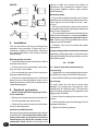
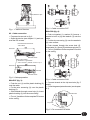
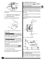
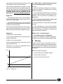
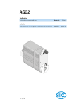
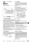
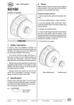
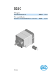
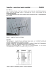
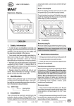
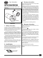
User Information
3. Summary description
The geared potentiometers are of very robust
design and compact size.
GP43/44/63/64
Geared Potentiometer With Limit
Switches
GP43/63
GP44/64
The gear mechanism / potentiometer combination adapts the mechanical rotating angle of the
1 or 10-turn potentiometer to the measuring
range. A slipping clutch between the gear mechanism and the potentiometer prevents irreparable mechanical damage to the potentiometer,
if the end stop is overtravelled (only valid for 10turn potentiometer; 1-turn potentiometers do not
have an end stop).
The geared potentiometers GP63/64 is equipped with an R-I transformer. The resistance
values relating to the potentiometer position are
converted into a loop current in the range 4 to
20 mA. This allows a measuring value transmission independently from the transmission line's
resistance.
Max. 3 trip control 3 switching actions.
ENGLISH
4. Warranty information
Please handle the encoder carefully as it is a
high-precision device.
1. Safety information
In order to carry out installation correctly, we
strongly recommend this document is read very
carefully. This will ensure your own safety and
the operating reliability of the device.
• Your device has been quality controlled, tested and is ready for use. Please respect all
warnings and information which are marked
either directly on the device or in this document.
• Warranty can only be claimed for components
supplied by SIKO GmbH. If the system is used
together with other products, the warranty for the
complete system is invalid.
• Repairs should be carried out only at our
works. If any information is missing or unclear,
please contact the SIKO sales staff.
Especially do not:
• disassemble or open the encoder (unless
stipulated in this brochure).
• link encoder's shaft with rigid couplings as this
would expose the encoder's shaft bearing to
high forces. For solid shaft encoders we recommend the use of SIKO flexible shaft coupling
type AK18.
• knock the housing and the shaft, because this
will damage the encoder or internal parts.
• machine (bore, mill ...) flange or shaft. This
could lead to severe damage inside the encoder.
• exceed the values for the maximum axial and
radial shaft load.
2. Identification
• mount the encoder incorrectly.
Please check particular type of unit and type
number from the identification plate. Type number and the corresponding execution are indicated in the delivery documentation.
Otherwise manufacturer's warranty will be invalidated!
e.g. GP43-0023
type number
type of unit
GP43/44/63/64
Datum 31.01.2000
Art.Nr. 79804
Z.Nr. 8604015
Änd.Stand 462/99
7
NEVER ...
choice of cable can minimise the effects of
interference (eg. interference caused by switching power supplies, motors, cyclic controls
and contactors).
Necessary steps:
• Only screened cable should be used. Screen
should be connected to earth at both ends. Wire
cross section is to be at least 0,14 mm2, max.
0,5 mm2.
• Wiring to screen and to ground (0V) must be
via a good earth point having a large surface area
for minimum impedance.
• The unit should be positioned well away from
cables with interference; if necessary a protective screen or metal housing must be provided. The running of wiring parallel to the mains
supply should be avoided.
5. Installation
The unit should be used only according to the
protection level provided. Protect the unit, if
necessary, against environmental influences
such as sprayed water, dust, knocks, extreme
temperatures.
Mounting of the encoder
• Contactor coils must be linked with spark
suppression.
Supply voltage of the instrument transformer
Operating voltage depends on execution and is
indicated in the delivery documentation or on the
identification plate.
• Use the frontal bores to fix the encoder. Mount
encoder without force.
20 ... 28 VDC
• Forces must not be transmitted via the housing, but only via the shaft.
6.1 How to open and close the device
• Do not exceed the values for the maximum
axial and radial shaft load.
• To open the unit, remove fastening screws on
the GP44/64's cap (on GP43/63's back wall).
• Ensure accurate shaft alignment. If shaft and
flange are not correctly aligned, strain on the
bearings will result, which will overheat and be
irreparably damaged.
• Ensure that the sealing is not damaged or lost.
6. Electrical connection
• Switch power off before any plug is inserted or removed !!
• Wiring must only be carried out with power off.
• Provide standed wires with ferrules.
• Check all lines and connections before switching on the equipment.
For opening:
For closing:
To easily close the unit and to avoid cable
damage, we recommend securing the inner
strands with an adhesive tape. The adhesive
tape should be insensitive to temperature and
ageing (only GP44/64):
• Ensure that the sealing lies correctly in the
groove.
• Put the cap/back wall onto the flange. Do not
damage the sealing.
• Tighten the fastening screws.
Interference and distortion
All connections are protected against the effects
of interference. The location should be selected to ensure that no capacitive or inductive
interferences can affect the encoder or the
connection lines! Suitable wiring layout and
8
GP43/44/63/64
Datum 31.01.2000
Art.Nr. 79804
Z.Nr. 8604015
Änd.Stand 462/99
Adhesive tape
Fig. 3 : Cable connection PG7
Fig. 1 : Fixation of ferrules
With PG9 (fig. 4) :
6.2 Cable connection
• Prepare wire accord. to fig. 2
• Open the device (see chapter 6.1) and unscrew the PG-screws.
Potentiometer/transducer
*Cam switch
• Push nut+gasket (1), washer (2) (inner-ø >
washer's inner-ø (4)) and washer (4) onto the
cable.
• Put the wire screening (3) over the washer's
(2) outer surface.
• Push strands through the screw hole (5).
Insert parts (4), (3) and (2) into the screw hole (5).
GP43/63
Ferrule
• Fix nut (1) and then fix the complete PG-screw
to the casing.
Shrink sleeve
Wire cross section :
2
- 2x0.25mm or 3x0.25mm2
- *max. 7x0.5mm2 (number of cams x 2) +1
GP44/64
Ferrule
Shrink sleeve
Fig. 2 : Cable preparation
Fig. 4 : Cable connection PG9
With PG7 (fig. 3) :
• Push the nut (1) and the plastic bushing (2)
onto the cable.
• Connect strands to the clip terminals (fig. 5
and 6).
• Put the wire screening (3) over the plastic
bushing (2).
• Close the geared potentiometer (see chapter
6.1).
• Slide strands through screw hole (4). Insert
plastic bushing (2) into the screw fitting.
Potentiometer
• Fix nut (1) and then fix the complete PG-screw
to the casing.
Trip cams
Fig. 5 : Pin connection GP43/44
GP43/44/63/64
Datum 31.01.2000
Art.Nr. 79804
Z.Nr. 8604015
Änd.Stand 462/99
9
7.3 Adjustment of the trip cams
Output
transducer
Ex works the trip cams are not fixed radially to
the shaft. Adjustment is made after installation.
Important information!
Do not touch the roller levers during trip cam
adjustment: damage from bending may result.
Trip cams
Fig. 6 : Pin connection GP63/64 with Instrument
transformer
• Bring the turnable trip cams (A, B, C) into a
position which is favorable for fine adjustment:
grub screw (1) and screw (2) must be easily
accessible.
7. Adjustment and alignment
• Fix the grub screws (1) to prevent straining of
the trip cams.
• The setting screw (2) is used for precise
setting of the trip cam; use a screw driver size 3
(see fig. 8).
7.1 General information
Definition of the counting directions:
Hexagon
socket 1,5
Fig. 7 : Definition of the counting directions
For GP43/44:
By direction of rotation "i" and turn the shaft in
direction "e" up to the limit stop, the value of the
moving contact (S) and the start point (Po)
value are 0 Ohm. The value increases – related
to Po – with clockwise rotation "i".
Screw driver 3
Fig. 8 : Trip cam adjustment
By direction of rotation "e" and turn the shaft in
direction "i" up to the limit stop, the value of the
moving contact (S) and the start point (Po)
value are 0 Ohm. The value increases – related
to Po – with anti-clockwise rotation "e".
For GP63/64:
...the same as for GP43/44, but the current of
the transducer starts at low values and increases towards the end point (see also chapter 7.4).
7.2 Potentiometer setting
When correctly connected and switched on, the
unit displays the current actual value.
Fig. 9 : Nomogram: Load rating cam switches
7.4 Alignment of the instrument transformer (only for GP63/64)
The unit GP63/64 comprises a resistance current converter. The potentiometer's resistance
is converted into a current of 4 ... 20mA (twin-
10
GP43/44/63/64
Datum 31.01.2000
Art.Nr. 79804
Z.Nr. 8604015
Änd.Stand 462/99
core cable). The measuring current is also used
for feeding the instrument transformer.
7.5 What to do if... (Instrument transformer)
The instrument transformer is preset to standard values 4mA for potentiometer's start position (Po) and 20mA for end position (Pe). Via
two trimmpotentiometer's Po and Pe (see fig.
6) these values can be adjusted to the
application's actual start and end position:
You can:
• either mechanically change the counting direction (by ordering / modifiying the counting
direction at SIKO),
Alignment:
• Trimmpotentiometer's Po is used to adjust a
current of 4 mA to potentiometer values of 0 to
15% of the total range.
...the counting direction is wrong?
• or by inverted interpretation of the 4 to 20 mA
current (4 mA would then correspond to the end
position; can be achieved via software programming).
... if the instrument transformer's start / end
value cannot be set to 4 / 20 mA?
• Trimmpotentiometer's Pe is used to adjust a
current of 20 mA to potentiometer values of 90
to 100% of the total range.
• the potentiometer's setting range is perhaps
to small.
The smallest available potentiometer range, in
which 4 to 20 mA are delivered, is hence 15% to
90% of the potentiometer's resistance range.
• check, whether you can do with a smaller
current range; otherwise adjust the gear's input
ratio accordingly ( by ordering / changing the
counting direction at SIKO).
Alignment
What to do if... (Potentiometer)
1) Move axis to start position.
... an undefined value is displayed?
• Carry out re-alignment or precise alignment.
Undefined values can be caused by cable breaks.
2) Turn left potentiometer (Po) until start value
(4mA) is measured.
3) Move axis to end position.
8. Starting
4) Turn right potentiometer (Pe) until end value
(20mA) is measured.
Please ensure that the instructions given in
chapter 5 and 6 regarding mechanical and electrical connection are followed. This will ensure
correct installation and the operating reliability of
the device.
The steps 1 to 4 are to be repeated until the
values are counterbalanced.
Before starting check again:
Current
• correct polarity of the supply voltage
(Pe)
20mA
• correct cable connection
• correct mounting of the device
4mA
(Po)
0
Distance
Fig. 10 : Alignment
GP43/44/63/64
Datum 31.01.2000
Art.Nr. 79804
Z.Nr. 8604015
Änd.Stand 462/99
11
SIKO
GmbH
DR.-ING. G. WANDRES
Postanschrift / Postal address:
Postfach 1106
D-79195 Kirchzarten
Werk / Factory:
Weihermattenweg 2
D-79256 Buchenbach
Telefon / Phone 0 76 61 / 3 94 - 0
Telefax / Fax
0 76 61 / 3 94 - 388
Internet www.siko.de
12
GP43/44/63/64
Datum 31.01.2000
Art.Nr. 79804
Z.Nr. 8604015
Änd.Stand 462/99