1
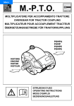
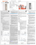
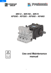
Menu
ISTRUZIONI D’USO E MANUTENZIONE
SÄKERHETSINSTRUKTIONER OCH UNDERHÅLL
USER AND MAINTENANCE INSTRUCTIONS
BRUGS- OG VEDLIGEHOLDELSESMANUAL
MODE D’EMPLOI ET D’ENTRETIEN
KÄYTTÖ- JA HUOLTO-OHJEKIRJA
GEBRAUCHS- UND WARTUNGSHANDBUCH
INSTRUKSJONER FOR BRUK OG VEDLIKEHOLD
INSTRUCCIONES DE USO Y MANTENIMIENTO
ΟΔΗΓΙΕΣ ΧΡΗΣΗΣ ΚΑΙ ΣΥΝΤΗΡΗΣΗΣ
INSTRUÇÕES DE USO E MANUTENÇÃO
ИНСТРУКЦИИ ПО ЭКСПЛУАТАЦИИ И
ТЕХОБСЛУЖИВАНИЮ
INSTRUCTIES VOOR GEBRUIK EN ONDERHOUD
Questo manuale deve essere letto e compreso in accordo al libretto specifico della pompa.
This manual should be read in conjunction with the manual provided with the pump.
Ce manuel doit être lu et compris en accord avec la notice spécifique de la pompe.
Dieses Handbuch muss zusammen mit der speziellen Bedienungsanleitung der Pumpe gelesen und verstanden werden.
Este manual debe leerse y entenderse de acuerdo con el manual específico de la bomba.
Este manual deve ser lido e compreendido de acordo com o manual específico da bomba.
Deze handleiding dient te worden gelezen en begrepen in samenhang met het specifiek bij de pomp geleverde instructieboekje.
Denna manual ska läsas och förstås tillsammans med pumpens specifika manual.
Denne manual skal læses og forstås i overensstemmelse med den specifikke manual til pumpen.
Tätä ohjekirjaa on luettava ja tulkittava yhdenmukaisesti pumpun käyttöohjeen kanssa.
Denne håndboken må leses og forstås i samsvar med pumpens spesielle håndbok.
Το εγχειρίδιο αυτό πρέπει να διαβαστεί και να κατανοηθεί σύμφωνα με το ειδικό εγχειρίδιο της αντλίας.
Данные инструкции должны прочитываться и использоваться вместе с инструкциями на конкретный насос.
ENGLISH
- Original Instructions THIS MANUAL CONTAINS THE INSTRUCTIONS REQUIRED TO INSTALL INTERPUMP PUMPS AND
PROVIDES THE INSTALLATION ENGINEER WITH THE NECESSARY INFORMATION ON THEIR USE
AND MAINTENANCE. IT THUS FORMS AN INTEGRAL PART OF THE INSTRUCTIONS AND SHOULD
BE READ CAREFULLY BEFORE PROCEEDING TO PERFORM ANY OPERATIONS, AND KEPT WITH
CARE.
FOLLOW THE INSTRUCTIONS SCRUPULOUSLY IN ORDER TO ENSURE SAFE AND EFFICIENT
OPERATION. FAILURE TO DO SO MAY CAUSE FAULTS TO OCCUR PREMATURELY AND CREATE
HAZARDS, AS WELL AS MAKING THE GUARANTEE NULL AND VOID.
1 - GENERAL INFORMATION
1.1 - The installation engineer is responsible for passing this information on to the end user to ensure
that the machine on which the pump is to be installed is used properly.
INTERPUMP GROUP declines all liability for any damage caused by negligence or failure to respect
the rules contained in this manual.
1.2 - The STANDARD pumps work with clean, soft water, at a maximum temperature of 40°C, and, only
for short periods, up to 60°C. In the latter case, call the Technical Department or the Customer Care
Department to establish the specifications required according to the type of plant installed.
The HT series pumps are specially designed to work with clean, soft water at a temperature of up to
85°C.
The SS series pumps are specially designed to work with salty water, demineralized water and other
aggressive solutions; for the latter, call the Technical Department or the Customer Engineering Service
to assess compatibility and the specifications required according to the type of application.
The performance indicated in the catalogue refers to the maximum performance provided by the pump.
Irrespective of the power used, the pressure and maximum number of revolutions indicated in the
catalogue cannot be exceeded unless expressly authorized by the Technical Department or Customer
Engineering Service.
1.3 - Improper use of pumps and high-pressure systems and failure to respect installation and
maintenance regulations may cause serious injury to persons and/or damage to things.
No reasonably applicable safety precaution must be omitted by the Installation engineer or the
Operator.
Any person responsible for assembling or using high-pressure systems must have the competence
required to do so, be familiar with the characteristics of the components he is about to assemble/
use and adopt all necessary precautions required to guarantee maximum safety under all operating
conditions.
1.4 - Considering that the pump is incorporated in a complete system, its installation and use should
be suitable for the type of system and conform to the safety regulations in force in the country where
it is to be used.
1.5 - Before using the pump, make sure that the system in which it is incorporated has been declared
compliant with the provisions laid down by the applicable Directives and/or standards.
1.6 - Before installing and using the pump received, we recommend you check its condition and that its
ratings correspond to those required. If they do not, avoid starting the pump and contact the Customer
Engineering Service for instructions.
1.7 - The pump must be assembled and installed by qualified staff, with the necessary mechanical and
technical skills, following the user and safety instructions given in this manual and the manual provided
with the pump.
1.8 - High-pressure system components, particularly those of systems that run mainly outdoors, must
be adequately protected against the rain, frost and heat.
8
A suitably-calibrated overpressure valve must be installed, as well as the pressure
regulating valve, must be installed on the high-pressure line.
The high-pressure pipes must be correctly sized for the system’s maximum working
pressure and used exclusively within the working pressure range indicated by the pipe
manufacturer and marked on the pipe itself.
The ends of the high-pressure pipes must be sheathed and secured to a solid structure,
so as to avoid the risk of whiplash if the connections burst or break.
The pump transmission systems (joints, pulleys, belts, rotary shafts), must be suitably
covered by a protective case.
If in doubt, do not hesitate to call the INTERPUMP GROUP Customer Engineering
Service.
2 - INSTALLATION
2.1 - The pump should be installed in a horizontal position using the supporting feet or coupled directly
to the motor using the original flange provided.
2.2 - The base must be flat and rigid so as to avoid bending and misalignments along the pump/motor
coupling axis.
2.3 - The pump/motor assembly cannot be fixed rigidly to the frame or base, anti-vibration elements
must be set in between.
2.4 - Avoid installing and using the pumps near heat sources and/or in environments where condensation
may form as this affects the effectiveness of the lubricant contained in the pump.
2.5 - Make sure that the pump never operates dry even for short periods by installing safety devices
on the system.
2.6 - For pumps with a built-in regulating valve or if the plant has the pressure regulating valve outlet
(BYPASS) connected directly to the feed inlet (IN) of the pump, the pump must not be operated in
BYPASS mode for more than 3 minutes, otherwise there will be a risk of damage to the seals and
valves caused by overheating.
For special applications, contact the Technical Department or the Customer Engineering Service.
3 - FEED LINE
To ensure the pump works to its full potential, the feed line must have the following
characteristics:
3.1 - An inside diameter at least as large as the (IN) inlet on the pump manifold; along the pipe avoid
fitting 90° elbows, connections with other pipes, chokes, “T” connections, siphons, areas where air
bubbles may stagnate and cause head losses and cavitation.
3.2 - The lay-out must be such as to ensure, under all working conditions, a positive head of between
min. 0.20 m (0.02 bars) and max. 100 m (10 bars) measured at the pump feed inlet; this minimum value
is valid for cold water having a temperature of up to 20°C, for higher temperatures, see the graph on
the last page.
9
3.3 - It must be completely airtight and designed in such a way that its seal is guaranteed to last in
time.
3.4 - It must be equipped with a filter of a suitable size, according to the capacity of the pump, and with
a filtering degree of min. 300 μm; the filter must be positioned as close as possible to the pump feed
attachment.
N.B. Even if the water to be used is clean, the filter must be installed to prevent foreign bodies present
in the plant such as swarf, welding slag or limestone scaling from entering the pump.
3.5 - Flexible piping should be used in the section closest to the pump so as to prevent forced
connections and the transmission of vibrations.
3.6 - It must be designed in such a way as to avoid the pump emptying even only partially when it
comes to a halt.
4 - DELIVERY LINE
The following rules should be respected in designing the DELIVERY line:
4.1 - The inside diameter of the piping must be correctly sized according to the maximum pressure and
capacity so as to ensure the appropriate speed of the fluid and to limit head losses.
4.2 - The first section of piping connected to the pump must be flexible, so as to avoid forced connections
and to isolate the vibrations produced by the pump from the rest of the plant.
4.3 - Use should be made of pressure gauges capable of withstanding the pulsating loads typical of
piston pumps, installed in such a way as to measure the pressure directly at the pump manifold.
4.4 - In the design phase, consideration should be given to the head losses on the line, which result in
a drop in working pressure with respect to the pressure measured at the pump.
4.5 - A suitably sized pulsation damper should be installed for applications in which the pulsations
produced by the pump on the delivery line have an undesired or detrimental effect.
Use high-pressure pipes and fittings suited to the working pressures that may arise
under all operating conditions.
Install a suitably calibrated overpressure valve, as well as the pressure regulating
valve.
5 - MAINTENANCE
5.1 - System maintenance work should be done within the time intervals laid down by the system
manufacturer, who is responsible for the entire assembly in accordance with the law.
5.2 - Correct maintenance prolongs the life of the pump and maintains its maximum performance in
time.
5.3 - All maintenance work should be done by specialized, authorized staff.
5.4 - The pump and its components are to be assembled and disassembled exclusively by authorized
staff, using equipment suited to the purpose so as to avoid damaging components that could put their
safety at risk.
5.5 - When it is to be scrapped, we recommend you take the pump to an authorized waste disposal
centre or call your local INTERPUMP GROUP Authorized Service Centre.
10
5.6 - Scheduled maintenance:
After the first 50 hours
Every 500 hours
Every 1000 hours (mean period: should be reduced for harsh operating condition)
Oil change
Oil change
Checking/replacement: Valve assemblies, pumping seals.
For the recommended oils, see the table on the last page of this manual.
WARNING: All used oil should be collected in containers and delivered to authorized
centres for disposal in accordance with the regulations in force. In no circumstances
shall it be dumped in the environment.
WARNING: To guarantee absolute reliability and safety, use should be made exclusively
of original spare parts.
6 - GUARANTEE CONDITIONS
6.1 – The guarantee period and conditions are indicated in the purchase agreement.
6.2 – The guarantee will, in any case, be considered null and void if the pump is used for improper
purposes, coupled with motors having a power higher than those indicated, used at pressures or
speeds higher than those indicated, repaired with non-original spare parts or if it is damaged as a result
of a failure to following the instructions given in this manual.
7 - START-UP
Replace the RED transport cap with the cap with a built-in dipstick provided.
7.1 - Check the oil level through the window or using the dipstick and, if necessary, top it up.
7.2 - Make sure that all fittings are securely tightened and that the pump feed is open.
7.3 - To expel the air present in the pump and make it easier to fill, we recommend you detach the
delivery pipe from the pump or keep the appliance/s open without any nozzles fitted.
7.4 - Start the pump for 5/10 seconds until the liquid flows out smoothly from the delivery pipe or
appliances; if this does not happen, stop the pump and repeat the operation after a 10-second pause.
7.5 - Complete the connections and/or install the nozzles.
7.6 - All INTERPUMP pumps are tried and tested prior to shipment, the installation engineer is, however,
obliged to test the complete system for an adequate time to check for leaks, overheating, deterioration
in performance or calibration, etc.
Calibrate or regulate the valves; to prevent tampering, apply lead seals where possible,
or paint the regulating registers so that any tampering can be readily detected.
11
8 - TROUBLESHOOTING GUIDE
At start-up, the
pump makes
no noise
• The pump is not primed and is operating dry, without lubricant
• The water supply is off.
• The valves are blocked.
• The delivery line is closed and does not let the air flow out of the pump.
The pipes
pulsate in
an irregular
fashion.
• There is insufficient air suction and/or supply.
• Bends, elbows, fittings on the feed line are slowing down the flow of the liquid.
• The feed filter is dirty or too small.
• The booster pump, if installed, is providing an insufficient pressure and/or capacity.
• The pump is not primed due to an insufficient head, the delivery pipe closing during
priming and/or a valve sticking
.• Worn pressure valves and/or seals and/or transmission problems.
• The pressure regulating valves are not working properly.
The pump
does not give
the rated
capacity
and makes
excessive
noise.
• There is an insufficient supply and/or the number of revolutions is less than the
rated value.
• Excessive leaking from the pressure regulating valve and/or the pressure seals.
• Worn valves.
• Cavitation due to undersized feed pipes and/or filter, insufficient capacity, high water
temperature, clogged filter.
The pressure
supplied by
the pump is
insufficient.
• The appliance (nozzle) is too large or is worn.
• Excessive leaking from the pressure seals.
• The pressure regulating valve is not working properly and/or the valves are worn.
The pump
overheats:
• The pressure and/or the number of revolutions is higher than the rated value.
• The oil in the sump of the pump is not at the required level or is not of the
recommended type.
• The belt is too tight, the joint or the transmission is not aligned.
COPYRIGHT The contents of this manual are the property of INTERPUMP GROUP, and the reproduction
and/or divulgation of all or part of the manual is strictly prohibited.
The information given in this document may be modified at any time without notice.
12
Revisione 3
PRESSIONE MINIMA DI ALIMENTAZIONE - MINIMUM FEED PRESSURE - PRESSION D’ALIMENTATION
MINIMUM - MINIMALER SAUGDRUCK - PRESIÓN MÍNIMA DE ALIMENTACIÓN - PRESSÃO
MÍNIMA DE ALIMENTAÇÃO - MINIMUM TOEVOERDRUK - MINIMUMSTILFØRSELSTRYK - MINSTA
TILLOPPSTRYCK - MINIMISYÖTTÖPAINE - LAVESTE TRYKK VED INNTAK
ΕΛΑΧΙΣΤΗ ΠΙΕΣΗ ΤΡΟΦΟΔΟΣΙΑΣ - МИНИМАЛЬНОЕ ДАВЛЕНИЕ ПОДАЧИ
VIA E. FERMI, 25 - 42049 S. ILARIO - REGGIO EMILIA (ITALY)
TEL. +39 - 0522 - 904311 - TELEFAX + 39 - 0522 - 904444
E-mail: [email protected] - http: //www.interpumpgroup.it
68
Cod. 31.0072.03 - 09/2009 - 20.000 De Pietri
OLI CONSIGLIATI - Salvo diverse indicazioni sul libretto specifico pompa.
RECOMMENDED OILS - Unless otherwise indicated in the manual provided with the pump.
HUILES CONSEILLÉES - Sauf indications différentes sur le livret spécifique de la pompe.
EMPFOHLENE ÖLSORTEN - Vorbehaltlich anders lautender Angaben in der speziellen Bedienungsanleitung
der Pumpe.
ACEITES RECOMENDADOS - Salvo indicaciones diversas en el manual específico de la bomba.
ÓLEOS ACONSELHADOS - Salvo indicações diferentes no manual específico da bomba.
AANBEVOLEN OLIESOORTEN - Behoudens andere vermeldingen in het specifieke bij de pomp horende
instructieboekje.
ANBEFALET OLIER - Med mindre andet er angivet i den specifikke brugsanvisning for pumpen.
REKOMMENDERADE OLJOR - undantaget specifika angivelser i pumpens specifika manual.
SUOSITELLUT ÖLJYT - Ellei pumpun käyttöohjeessa muuta ilmoiteta.
ANBEFALTE OLJER - Hvis ikke annet angis i pumpens spesielle håndbok.
ΠΡΟΤΕΙΝΟΜΕΝΑ ΛΑΔΙΑ - Εκτός κι αν υποδεικνύεται διαφορετικά στο ειδικό εγχειρίδιο αντλίας.
РЕКОМЕНДУЕМЫЕ МАСЛА - Если не указывается иначе в инструкциях на конкретный насос.
1 - CAMBIO OLIO
1
2
1.1 – Il cambio dell’olio va eseguito con pompa a
temperatura di lavoro.
1.2 – Posizionare un recipiente sotto il tappo di scarico olio (3).
1.3 – Rimuovere il tappo con asta (1) e successivamente il
tappo di scarico (3).
1.4 – Attendere fino a quando tutto l’olio è uscito, quindi
riavvitare il tappo di scarico (3) con la coppia torcente indicata
su disegno esploso.
1.5 – Riempire con olio nuovo fino al raggiungimento della
mezzeria del tappo spia livello olio (2) e riavvitare il tappo con
asta (1) .
Per il tipo di olio da utilizzare fare riferimento a quanto indicato sul libretto generico.
ATTENZIONE: L’olio esausto deve essere raccolto in recipienti e smaltito negli
appositi centri in accordo alla normativa vigente. Non deve essere assolutamente
disperso nell’ambiente.
1 – OIL CHANGING
1.1 – Oil changing must be done with the pump at operating temperature.
1.2 – Put a container under the oil drain plug (3).
1.3 – Remove the oil dipstick (1) and then the drain plug (3).
1.4 – Wait until all the oil has drained out, then screw the drain plug (3) and tighten at the torque shown in
the exploded diagram.
1.5 – Fill with new oil until the middle of the oil level indicator (2) is reached, screw by hand the oil dipstick
(1).
Refer to the generic booklet for the type of oil to use.
WARNING: The exhaust oil must be collected in receptacles and disposed of at
authorised centres as specified by law. It must not be thrown away in the
environment.
1 - CHANGEMENT DE L’HUILE
1.1 – Le changement de l’huile doit être exécuté avec la pompe à température d’exercice.
1.2 – Placer un récipient sous le bouchon de vidange de l’huile (3).
1.3 – Enlever le bouchon-jauge (1), puis enlever le bouchon de vidange (3).
1.4 – Attendre que toute l’huile soit sortie, puis revisser le bouchon de vidange (3) avec le couple de
torsion qui est indiqué sur le dessin éclaté.
1.5 – Remplir avec de l’huile neuve jusqu’à la ligne médiane du bouchon indicateur du niveau d’huile (2), et
revisser le bouchon-jauge (1).
Pour le type d’huile à utiliser, se référer à ce qui est indiqué sur la notice générale.
ATTENTION : L’huile usée doit être recueillie dans des récipients et éliminée dans les
centres prévus à cet effet, conformément à la réglementation en vigueur. Il ne faut
absolument pas la jeter dans l’environnement.
7
3