1
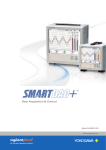
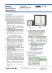
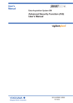
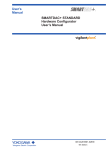
Data Acquisition System
Data Acquisition & Control
Bulletin 04L55B01-01EN
www.smartdacplus.com
Data Acquisition & Control
Your business environment is complex and rapidly changing.
You need smart and powerful systems that can adapt to your process.
is a fresh approach to data acquisition and control,
with smart and simple touch operation as a design priority.
Measure, display and archive process data with greater
levels of clarity, intelligence and accessibility.
The
concept started with the GX/GP,
an integrated I/O and recording system
with a familiar touch operator interface.
Building upon the
product family is
the highly adaptable, scalable and easy to
operate GM data logger.
Now that’s SMART.
Precise, Reliable &
Decades of Yokogawa's innovative measuring technology has resulted
in a flexible data logger that offers both reliability and ease of use.
Scalability
Reliability
to 420 ch per system
● Plug and lock modules
● Secure
● Up
Ease of Use
● Web-based
● Live
configuration
Web-based data viewing
Mobile Connectivity
● Bluetooth
● Mobile
2
Application
data storage
● High accuracy measurement
● Automatic backfill function
(GA10 Data Logging Software)
Noise Tolerance
● Electromagnetic
relay module
Adaptable
Enables a scalable data acquisition system
Smart Architecture
Provides a smooth, familiar user experience
Smart User Interface
Ethernet
Ethernet
Offers a seamless data transfer environment
Smart Functionality
Spreadsheet
3
Smart Architecture
Enables a scalable data acquisition system
Increase channels
by adding additional block modules
Names of data acquisition module parts
YOKOGAWA proprietary block architecture (patent pending)
• Expand one, or multiple module at a time
• Unique design houses modules in linked module bases
base ensures linkage (slide locks and mounting screws also
• Module
available)
can be inserted and removed from the front panel for easy
• Modules
maintenance
Status display
(Displays system status)
7 segment LED (x2)
(Displays operation mode, system
number, and other information)
START/STOP key
(Starts/stops recording and
computation)
USER key
(Executes specified actions)
USB port
(USB2.0 compliant port for hardware
settings and the GA10, or customer
created communication programs)
SD memory card slot
Ethernet port
A 10Base-T/100Base-TX port.
Serial communications port
(Optional code, /C3)
2 ways of linking:
slide lock and screw
Slide lock
Module Base
Screw
Link
Input/output Module
Power switch
Data Acquisition Module
Comes standard with support
for up to 100 ch of measurement
(single-unit configuration)
Up to 10 I/O modules can be linked to a
single data acquisition module (GM10)
Installs anywhere
For the desktop, DIN rails, or wall-mounting.
No special attachments required.
Desktop
Mounted on DIN rails
Wall-mounted
Up to 10 modules linked
4
Power Supply
Module
Inlet. For screw terminals,
acts as a power terminal
and protective ground
terminal.
Select from a wide range of I/O modules
Select modules according to your application.
Noise-resistant, magnetic relay types also available.
All modules have removable terminal blocks for easy wiring.
The same modules used in the SMARTDAC+ series.
Model
SMARTDAC+ series
Input/output terminals are removable.
Cuts down on rewiring time.
Name
Measurement/Application
DC voltage, thermocouple, RTD, contact (semiconductor
relay scanner type)
10
GX90XA-10-L1
DC voltage, thermocouple, contact (low withstand voltage)
10
Analog input module
GX90XA-10-T1
DC voltage, thermocouple, contact (electromagnetic relay
scanner type)
10
GX90XA-10-C1
DC current (mA)
10
Remote control input, operation recording, or pulse input
16
GX90XD
Digital input module
GX90YD
Digital output module
GX90WD
Digital input/output module
Alarm output
Channels
Scanner
Universal (-U2)
10
100ms
SSR
Universal
Low withstand voltage relay
(-L1)
10
500ms
SSR
Mid-price
Electromagnetic relay
(-T1)
10
1s
Relay
Noiseresistance
DC current input (-C1)
10
100ms
SSR
mA only
RTD
DI:8/DO:6
Internal memory and max. I/O channels
Scan interval
(shortest)
TC
6
Remote control input, operation recording or pulse input/
alarm output
Analog input module scan interval and measurement type
Type
Channels
GX90XA-10-U2
DCV
DI
mA
Use
Type
Internal
memory
GM10-1
500MB
GM10-2
1.2GB
: Available
Max. input/output channels
Single-unit
configuration
0 to 100
Multi-unit
configuration
0 to 100
Single-unit
configuration
0 to 100
Multi-unit
configuration
0 to 420
Actual values support high precision measurement
Input type
DCV
TC
RTD
Measuring accuracy* (typical value)
20mV
± (0.01 % of reading + 5 μV)
6V (1-5 V)
± (0.01 % of reading + 2 mV)
R
±1.1 °C
K (-200 to 500 °C)
±0.2 °C
However, -200.0 to 0.0 °C: ± (0.15% of reading + 0.2 °C)
T
±0.2 °C
However, -200.0 to 0.0 °C: ± (0.10% of reading + 0.2 ºC)
Pt100
± (0.02% of reading + 0.2 °C)
Pt100 (high resolution)
± (0.02% of reading + 0.16 °C)
The measuring accuracies noted in the general specifications on
page 11 have a margin of error that takes into account the product's
components and the equipment used for adjustment and testing.
However, the actual values calculated from the accuracy testing data
upon shipment of the instrument from the factory are listed to the left.
* General operating conditions: 23±2 ºC, 55±10% RH, supply voltage 90–132, 180–264
VAC, supply frequency within 50/60 Hz ±1%, warm-up of 30 minutes or more, no
vibrations or other hindrances to performance.
Support measurement of up to 420 ch (actual input) by
expanding channels across multiple units (multi-unit configuration)
Expand up to 420 ch by using the GX90EX expansion module. (GM10-2)
On the GM10-2 large capacity type, up to 1000 ch are available for recording
when including MATH and communication channels.
Connect units with Ethernet cables for dispersed installations.
Main unit
Reduce wiring with
distributed installation
When the data logger is installed offsite
(away from the DUT), you can place the
sub unit at the site and monitor data
without the need for long-distance wiring of
thermocouples and other sensors.
Sub unit
Main unit
LAN cable (CAT5 or later)
Thermocouples
Up to 100 m
The maximum distance
between units is 100 m
Sub unit
Chain up to 6 units
5
Smart User Interface
Provides a smooth, familiar user experience
Easy access from a Web browser
Through a Web browser you can monitor the GM in real time and change settings.
You can easily build a seamless, low-cost remote monitoring system with no additional software.
Real time monitoring screen
Ethernet
With the scroll bar, you can seamlessly scroll
between past and current trends.
Enter settings online with a web browser
The setting screen lets you copy AI channel settings and other
information to Excel for editing.
You can reimport the data into the setting screen after editing.
Trend, digital, and other real-time displays
Bar graph
Trend
Digital
6
Alarm/Message/Memory
summary
Overview
Dedicated software (free download) is available for loading
waveforms and GM settings
Universal viewer
Offline setting software
Data files saved on the GM can be viewed and printed.
You can perform statistical computation over an area
and export to ASCII, Excel, or other formats.
Save settings or transfer them to the GM.
Connections can also be made easily via USB or Bluetooth.
USB comes standard
(USB communication
function)
USB connection
SD card
Send/receive
settings
Ethernet
Load/save settings
Data converted to an ASCII file
Monitoring and settings can also
be done on a tablet
Supports Bluetooth (optional code /C8)
You can enter settings or monitor from a tablet without
ever bringing a PC to the site.
Safe to use in a wide range of
temperatures
With operating temperatures of -20°C–60°C, it supports
a wide range of applications without concern about the
installation enviroment.
Dedicated applications will be available for free download. For more
information, visit our website.
-20℃
60℃
Environmental testing
GA10 data logging software (sold separately)
Dedicated software available for powerful system configuration possibilities.
Acquires data from mutliple instruments including SMARTDAC+ GM
· Max. 100 devices
· 100 ms high-speed acquisition
· Max. 2000 channels (tags)
High reliability
•
•
Multilogging
Auto reconnection when communications are lost,
protection of data les up to the moment of power failure
Data supplementing function (Backfill function)
Muldilogging function enables multiple asynchronous data
acquisition jobs.
Data loss
n
tio
ica
un nce
m
e
r
m
C o te r f e
in
Recording
Testing
equipment A
Stopped
Testing
equipment B
Recording
Standby
Testing
equipment C
Test start
Test stop
Test start
Test start
Test stop
Test stop
no.1
no.2
no.3
Current time
Back-fills data on the main
instrument after communications
are restored
OS support
• Server
Enables construction of highly reliable systems
that hold up under continuous operation
Results: Manage data from multiple
equipment in one place!
7
Smart Functionality
Offers a seamless data transfer environment
Data acquisition on power measuring instruments (optional codes /E2 and /MC)
Acquire precise digital data on the GM by digital
communication connectivity to a power measuring
instrument (WT series power analyzers) and record it
along with the GM's measured data.
Since it records a device's power consumption,
temperature, and other phenomena at the same time,
the GM is ideal for performance evaluation testing.
Air conditioner
Temperature
Ethernet
Refrigerator
Models that can be connected
Yokogawa Meters & Instruments Corp. WT300/WT500/WT1800
Power
Max. no. of connections
16
Washing machine
Comes with communication functions that are compatible
with the DARWIN data acquisition unit
The GM supports DARWIN communication commands.
Use your current DARWIN communication programs asis on the GM.
It's easy to switch from an existing DARWIN unit.
User original programs
(includes DARWIN communication commands)
Ethernet or RS-422/485
* See your dealer or nearest Yokogawa representative for details.
CENTUM/STARDOM communciation package
CENTUM: LFS2432, DARWIN/DAQSTATION Communication package
(for ALE111 [Ethernet])
STARDOM: NT365AJ DARWIN connection package
Variety of convenient
networking functions
Supports a wide range of networking functions
• Automatic network setup via DHCP
• SNTP based time synchronization
• Email transmission
FTP-based file transfer
The FTP client/server functions allow you to easily share and
manage data from a centralized file server
FTP client function
FTP server function
FTP client
Increased network security
with SSL communication
Safely sends and receives customer data.
Ethernet
Ethernet
Internal memory/external
storage:
Data files
Report files...etc.
Data files
Report files
SSL-based encryption
Primary
Secondary
FTP server
8
FTP server
EtherNet/IP
communication
Data reading
Data writing
EtherNet/IP Function
GM supports EtherNet/IP server functions.
You can access GM from PLCs or other devices and load
measurement/MATH channels or write to communication
input channels*.
PLC
Ethernet
* Communication channel function (optional code, /MC) is required.
Modbus/TCP and Modbus/RTU Communications
GM supports Modbus TCP/IP client and server modes for Ethernet communications and Modbus RTU master and slave
modes for optional serial communications.
Modbus TCP (Ethernet connection)
Modbus RTU (RS-422/485 connection)
Modbus client
Modbus master
The data of server units can be saved on the GM
using the Modbus/TCP function*.
The data of slave units can be saved on the
GM using the Modbus RTU function*.
*Communication channel function (optional code, /MC) is required.
*Communication channel function (optional code, /MC) is
required.
(Up to 16 (GM10-1) or 32 (GM10-2)
servers can be connected.)
GP10
GX10
Ethernet
MW100
(Up to 32 slaves can be connected.)
UTAdvanced series controller
FA-M3V
RS-422/485
Power monitor etc.
Be confident that recorded data is saved
Supports long-duration and multichannel recording. Measured data is
always stored to internal memory, and data is transferred to external
storage media at regular intervals. Redundancy can be achieved by
sending data to a server with the FTP client function. Securely saves
measured data even in the event of a sudden power loss.
Measured data
Data file
A
Approximate sample time
Data file
Number of recording channels
Total sample time
30
Approx. 71 days
100
Approx. 23 days
300
Approx. 7 days
B
Data file
C
Internal memory
With an internal memory of 1.2 GB and recording interval of 1 sec.
Data file
Auto save
Copy
A
Data file
B
Data file
C
External strage medium (SD card)
Measured data file type
You can save measured data to editable text files, or to binary files for added security.
Report template function (optional code /MT)
Supports 21 CFR Part 11
(pending; with added specs)
This function automatically creates spreadsheets in PDF or Excel format.
Excel spreadsheet template
PDF spreadsheet template
Spreadsheets generated from PDF spreadsheet
templates can be automatically output from the GM
to a printer through a PC.
Load template
GM supports the USA FDA’s Title 21
CFR Part 11 regulation.
PDF
Excel
SD card
Spreadsheets are created according to the template
loaded on the main unit. Templates are available for
Excel and PDF. PDF spreadsheet templates are created
with a free report template builder program.
Spreadsheet created automatically
Automatically generated spreadsheets (PDF
or Excel) are saved to external strage medium
(SD card) at regular intervals. You can also
transfer them via FTP.
9
Specifications
For detailed specs, see the general specifications
(data acquisition module/power supply module/module base: GS 04L55B01-01EN, expansion unit/expansion modules: GS 04L53B00-01EN, I/O modules: GS 04L53B01-01EN).
GM10 Data Acquisition Module
No. of I/O channels:
GM10-1: 100 max.
GM10-2: 500 max. (or 420 with AI only)
100/200/500 ms/1/2/5 s
Scan interval:
* Some intervals not available depending on system configuration and modules.
Internal memory (flash memory): GM10-1: 500 MB
GM10-2: 1.2 GB
SD memory card (SD/SDHC), up to 1–32 GB (1 GB incl.)
External storage media:
Format: FAT32 or FAT16
Event, display, alarm summary, manual sample, settings, and report
Data types:
(optional code /MT)
Binary or text
Data format:
Number: Max. 4 alarms per measurement channel
Alarms:
Types: high limit, low limit, difference high limit, difference low limit, rate of
change increase, rate of change decrease, delay high, delay low
Specified actions can be performed when certain events occur.
Event actions:
Number: 50
Events: alarms, remote control input, etc.; Actions: record stop/start, alarm ACK, etc.
Timers: 4
Match time timers: 4
Manage data by batch name. Enter text fields and batch comments in data files.
Batch function:
Key lock and login functions.
Security functions:
Between RS-422/485/Ethernet terminals and internal circuitry: 20 MΩ or greater
Insulation resistance:
(at 500 VDC)
●●Ethernet
Electrical/mechanical
specifications:
Implemented protocols:
●● USB
IEEE 802.3 compliant (Ethernet frame type: DIX specification)
TCP, UDP, IP, ICMP, ARP, DHCP, HTTP, FTP, SMTP, SNTP, Modbus,
dedicated protocol, SSL, DARWIN-compatible communication
communication
USB 2.0 compliant (recognized as a serial port by the PC)
Standards conformity:
Connector format/no. of ports: mini B/1
Dedicated protocol
Implemented protocol:
●●RS-422/485
EIA RS-422/485 compliant
Dedicated protocol, Modbus/RTU, or DARWIN compatible communication
(optional code /C8)
Standards conformity:
Supported profiles:
Communication range:
Implemented protocol:
●●Ethernet/IP
Bluetooth® Ver 2.1+EDR compliant
SPP (serial port profile)
Approx. 10 m (depending on operating environment) (Class2)
Dedicated protocol
communications (optional code /E1)
Can join Ethernet/IP networks as an adapter (server).
20 (or 10 max. at TCP/IP level)
Max. connections:
EIP/PCCC, EIP/native
Supported protocols:
Explict (UCMM Class 3) +I/O (Class 1)
Messaging:
Assembly, PCCC, Data Table
Objects:
●●WT
communication (optional code /E2)
Models supported:
Supported communication:
Max. connected units:
Communication interval:
Acquirable data types:
Max. data assignments:
●●MATH
WT1800, WT500, WT300
Ethernet
16
500 ms/1 s/2 s/5 s/10 s/15 s/20 s/30 s
Voltage, current, power, power factor, phase, watt hours, harmonics, and others.
300
(with Report function, optional code /MT)
No. of MATH channels:
MATH types:
●●Communication
100
Basic math, statistics, special operators, conditional statements, and others.
channels (optional code /MC)
No. of communication
channels:
●●Log
Normal mode: 50/60 Hz no rejection (integral time 1.67 ms),
40 dB or more (integral time 16.67 ms or more)
Common mode: 80 dB or more (integral time 1.67 ms),
120 dB or more (integral time 16.67 ms or more)
30 VACrms (50/60Hz), or 60 VDC (however, max. common mode noise voltage
Max. common mode voltage:
of measurement input is 250 VACrms)
Universal, electromagnetic relay: 30 VACrms (50/60Hz), or 60 VDC (however,
Max. voltage between
max. common mode noise voltage between measurement input channels is 250
measurement input channels:
VACrms)
Low withstand voltage relay: 30 VACrms (50/60Hz), or 60 VDC (however, max.
common mode noise voltage between measurement input channels is 60
VACrms)
Effects of ambient temperature: Applies when integral time is 16.67 ms or higher, ±(0.05% of rdg + 0.05% of
range) or less fluctuation per 10°C change
Note, KpvsAu7Fe, PR20-40: ±(0.05% of rdg + 0.1% of range) or less
Cu10Ω system: ±(0.2% of range + 0.1°C ) or less
Excluding guaranteed reference junction accuracy
Between
input terminals and internal circuitry: 20 MΩ or greater (at 500 VDC)
Insulation resistance:
Universal, electromagnetic relay:
Withstand voltage:
Between input terminals and internal circuitry: 3000 VAC, 1 minute
Between analog input channels: 1000 VAC, 1 minute (excluding b terminal)
Low withstand voltage relay:
Between input terminals and internal circuitry: 1500 VAC, 1 minute
Between analog input channels: 400 VAC, 1 minute
DC current (mA) input (-C1)
Inputs:
Input types:
Integral time:
Input calculation:
Input range:
Input resistance:
Allowable input voltage:
Allowable input current:
Noise rejection ratio:
(optional code /C3)
Media:
Implemented protocol:
●●Bluetooth
Noise rejection ratio:
GM10-1: 300 (C001–C300)
GM10-2: 500 (C001–C500)
scale (optional code /LG)
Input types:
Scalable range:
LOG input, pseudo log (input that supports pseudo log), LOG linear
(linear input within the log decade)
LOG input: 1.00E-15 to 1.00E+15 (max. 15 decades),
[scale low limit] < [scale high limit]
Pseudo log input/LOG linear: 1.00E-15 to 1.00E+15 (max. 15 decades),
the mantissa of the scale low and high limits are assumed to be the same.
GM90PS Power Supply Module
Rated supply voltage:
Operating supply voltage:
Power frequency:
Insulation resistance:
Withstand voltage:
100–240 VAC
90–132 VAC, 180–264 VAC
50 Hz±2%, 60 Hz±2%
Between power terminal and earth: 20 MΩ or more (at 500 VDC)
Between power terminal and earth: 3000 VAC (50/60 Hz), 1 minute
GX90XA Analog Input Module
Universal input (-U2), low withstand voltage relay (-L1), electromagnetic relay (-T1)
Max. common mode voltage:
Max. voltage between
measurement input channels:
Effects of ambient temperature: Applies when integral time is 16.67 ms or more, ±(0.075% of rdg + 0.05% of
Insulation resistance:
Withstand voltage:
10
range) or less fluctuation per 10°C change
Between input terminals and internal circuitry: 20 MΩ or greater (at 500 VDC)
Between input terminals and internal circuitry: 1500 VAC, 1 minute
Between analog input channels: 1000 VAC, 1 minute
GX90XD Digital Input Module
Inputs:
Input format:
Range types
ON/OFF detection:
Input calculation:
Contact rating:
Input resistance:
No. of common:
Allowable input voltage:
Insulation resistance:
Withstand voltage:
16
Open collector or non-voltage contact
DI, pulse (max. 250 Hz, min. pulse width: 2 ms, requires the MATH (optional
code /MT)).
Open collector:
Voltage of 0.5 VDC or less when ON, leakage current of 0.5 mA or less when OFF
Non-voltage contact:
Contact resistance of 200 Ω or less when ON, 50 kΩ or more when OFF
Linear scaling, differential calculations
12 VDC, 20 mA or more
Approx. 1 kΩ
2 (1 common per 8 channels)
10 V
Between input terminals and internal circuitry: 20 MΩ or greater (at 500 VDC)
Between input terminals and internal circuitry: 1500 VAC, 1 minute
GX90YD Digital Output Module
Outputs:
Output format:
Rated load voltage:
Max. load current:
Min. load voltage/current:
No. of common:
Insulation resistance:
Withstand voltage:
6
Relay contact (c contact)
30 VDC or 250 VAC or less
3 A (DC)/3 A (AC), resistive load, each
5 VDC/10 mA
6 (all outputs independent)
Between output terminals and internal circuitry: 20 MΩ or greater (at 500 VDC)
Between output terminals and internal circuitry: 3000 VAC, 1 minute
GX90WD Digital Input/output Module
●●Digital
input (DI) section
Inputs:
Input format:
Range types:
ON/OFF detection:
Inputs:
Input types:
10
Universal: DC voltage, standard signal, thermocouple, RTD, DI (voltage contact),
DC current (with external shunt resistor connected)
Low withstand voltage relay, electromagnetic relay: DC voltage, standard
signal, thermocouple, DI (voltage, contact), DC current (with external shunt
resistor connected)
Universal: 1.67 ms/16.7 ms/20 ms/36.7 ms/100 ms
Integral time:
Low withstand voltage relay, electromagnetic relay:
16.7 ms/20 ms/36.7 ms/100 ms
Linear scaling, square root, differential calculations
Input calculation:
Refer to the Measurement range and accuracy table.
Input range/accuracy:
10 MΩ or more for thermocouple/DC voltage (1 V range or lower)
Input resistance:
Approx. 1 MΩ for DC voltage (2 V range or higher)/standard signal
2 kΩ or lower for thermocouple/DC voltage
Input external resistance:
±10
μV/1 kΩ or lower for thermocouple/DC voltage (1 V range or lower)
Effect of signal source resistance:
±0.15%/1 kΩ or lower for DC voltage (2 V range or higher)/standard signal
Max.
10 Ω/1 wire or less (lead resistance between 3 wires is equal) for RTD input
Allowable wiring resistance:
±0.1°C/10 Ω (lead resistance between 3 wires is equal) for RTD input
Effect of wiring resistance:
Measurement of 0°C or higher, input terminal temp. balanced
Reference junction
Type K, E, J, T, N, XK GOST: ±0.5°C (23°C±2°C), ±0.7°C (0 to 50°C), ±1.0°C
compensation accuracy:
(-20 to 60°C)
Type R, S, W, L, U, W97Re3-W75Re25, platinel 2, NiNiMo, W/WRe26,
N(AWG14): ±1.0°C (23°C±2°C), ±1.4°C (0 to 50°C), ±2.0 (-20 to 60°C)
Type KpvsAu7Fe: ±1.0 K (23°C±2°C), ±1.4 K (0 to 50°C), ±2.0 K (-20 to 60°C)
Type B, PR20-40: RJC fixed at 0°C
* Parentheses ( ) = ambient temperature.
±60V DC for DC voltage (2 V range or higher)/standard signal
Allowable input voltage:
±10 V DC for other conditions.
10
DC current (20 mA), standard current signal (4–20 mA)
1.67 ms/16.7 ms/20 ms/36.7 ms/100 ms
Linear scaling, square root, differential calculations
Refer to the Measurement range and accuracy tables.
250 Ω
±10 VDC
24 mA *50/60 Hz, peak value including the signal portion
Normal mode: 50/60 Hz no rejection (integral time 1.67 ms), 40 dB or more
(integral time 16.67 ms or more)
Common mode: 80 db or more (integral time 1.67 ms), 120 dB or more (integral
time 16.67 ms or more)
30 VACrms (50/60Hz) or 60 VDC (however, max. common mode noise voltage
of measurement input is 250 VACrms)
30 VACrms (50/60Hz) or 60 VDC (however, max. common mode noise voltage
between measurement input channels is 250 VACrms)
Input calculation:
Contact rating:
Input resistance:
No. of common:
Allowable input voltage:
Insulation resistance:
Withstand voltage:
●●Digital
8
Open collector or non-voltage contact
DI, pulse (max. 250 Hz, min. pulse width: 2 ms, requires the MATH (optional
code /MT)).
Open collector:
Voltage of 0.5 VDC or less when ON, leakage current of 0.5 mA or less when OFF
Non-voltage contact:
Contact resistance of 200 Ω or less when ON, 50 kΩ or more when OFF
Linear scaling, differential calculations
12 VDC, 20 mA or more
Approx. 2.4 kΩ
1 (1 common per 8 channels)
10 V
Between input terminals and internal circuitry: 20 MΩ or greater (at 500 VDC)
Between input terminals and internal circuitry: 1500 VAC, 1 minute
output (DO) section
Outputs:
Output format:
Rated load voltage:
Max. load current:
Min. load voltage/current:
No. of common:
Insulation resistance:
Withstand voltage:
6
Relay contact (c contact)
150 VAC or less when connected to the main circuit (first-order power supply)
250 VAC or less when connected to a circuit derived from the main circuit
(second-order power supply) , or 30 VDC or less
2 A (DC)/2 A (AC), resistive load, each
5 VDC/10 mA
6 (all outputs independent)
Between output terminals and internal circuitry: 20 MΩ or greater (at 500 VDC)
Between output terminals and internal circuitry: 2700 VAC, 1 minute
GX90EX Expansion Module
Connects via dedicated communication between main unit and subunits, and between subunits.
10Base-T/100Base-TX (Auto)
Communication speed:
2
Ports:
STP cable, CAT5 or later
Connection cable:
Connection between modules: Cascade connection (no ring connection)
100 m
Communication range:
Standards supported
UL61010-1、UL61010-2-030 (CSA NRTL /C)
SMARTDAC+ GM common specifications
EMC Regulatory Arrangement in Australia and New Zealand (RCM):
●●Standards
Wireless communication standards of Australia and New Zealand (RCM) (optional code /C8):
CSA:
EN55011 Class A Group 1
supported
CSA22.2 No61010-1, installation category II, pollution degree 2
CSA 22.2 No.61010-2-030-12
UL61010-1, UL61010-2-030 (CSA NRTL/C)
EMC directive:
EN61326-1 Class A Table 2
EN61000-3-2
EN61000-3-3
EN55011 Class A Group 1
Low voltage directives: EN61010-1, EN61010-2-030
Installation category II, pollution degree 2, measurement category II
R&TTE directive
HEALTH&SAFETY
(optional code /C8):
EN61010-1
EN61010-2-030
Installation category II, pollution degree 2, measurement category II
EN62311
EMC
EN301 489-1
EN301 489-17
EN61326-1
SPECTRUM
EN300 328
UL:
CE:
AS/NZS4268, AS/NZS2772.2
Electromagnetic wave interference prevention standard, electromagnetic wave protection
standard compliance
WEEE directive support
Environmental
KC marking:
performance:
Wireless
(Bluetooth):
●●Normal
Supports radio wave regulations of Japan, America, Canada, Europe (EU), Australia, New
Zealand, China, and Korea.
operating conditions
Ambient
temperature:
Ambient humidity:
Vibration:
Shock:
Magnetic field:
-20 to 60°C
If less, -20 to 50°C
· When using the GX90YD, GX90WD, and GX90XA-T1 (electromagnetic relay type)
· With the GM10/C8 (Bluetooth option)
20 to 85% RH (no condensation)
5 ≤ f < 8.4 Hz amplitude 3.5 mm (peak)
8.4 ≤ f ≤ 160 Hz acceleration 9.8 m/s2 (or less)
When ON, 98 m/s2 or less, 11 ms, 3 times in 6 directions (±X, ±Y, ±Z), (excluding GX90YD and
GX90WD)
When OFF, 500 m/s2 or less, approx. 10 ms, 3 times in 6 directions (±X, ±Y, ±Z)
400 A/m or less (DC and 50/60 Hz)
Measurement range and accuracy*
Input
DCV
Standard signal
DC current
DC current (standard signal)
Type
20mV
60mV
200mV
1V
2V
6V
20V
50V
0.4-2V
1-5V
0-20mA
4-20mA
R
S
-20.000 to 20.000 mV
-60.00 to 60.00 mV
-200.00 to 200.00 mV
-1.0000 to 1.0000 V
-2.0000 to 2.0000 V
-6.000 to 6.000 V
-20.000 to 20.000 V
-50.00 to 50.00 V
0.3200 to 2.0800 V
0.800 to 5.200 V
0.000 to 20.000mA
3.200 to 20.800mA
0.0 to 1760.0°C
0.0 to 1760.0°C
B
0.0 to 1820.0°C
K
TC
(Excluding RJC accuracy)
-270.0 to 800.0°C
J
-200.0 to 1100.0°C
T
-270.0 to 400.0°C
N
-270.0 to 1300.0°C
W
0.0 to 2315.0°C
L
-200.0 to 900.0°C
U
-200.0 to 400.0°C
A/D integration time: 16.7ms or more
±(0.05
±(0.05
±(0.05
±(0.05
±(0.05
±(0.05
±(0.05
±(0.05
±(0.05
±(0.05
%
%
%
%
%
%
%
%
%
%
of
of
of
of
of
of
of
of
of
of
rdg
rdg
rdg
rdg
rdg
rdg
rdg
rdg
rdg
rdg
+12 μ V)
+0.03 mV)
+0.03 mV)
+1.2 mV)
+1.2 mV)
+3 mV)
+3 mV)
+0.03 V)
+1.2 mV)
+3 mV)
A/D integration time: 1.67ms
±(0.1
±(0.1
±(0.1
±(0.1
±(0.1
±(0.1
±(0.1
±(0.1
±(0.1
±(0.1
%
%
%
%
%
%
%
%
%
%
of
of
of
of
of
of
of
of
of
of
rdg
rdg
rdg
rdg
rdg
rdg
rdg
rdg
rdg
rdg
+40 μ V)
+0.15 mV)
+0.4 mV)
+4 mV)
+4 mV)
+15 mV)
+40 mV)
+0.15 V)
+4 mV)
+15 mV)
±(0.3 % of rdg +5 μ A)
±(0.3 % of rdg +90 μ A)
±(0.15 % of rdg +1.0°C)
however, R, S; 0.0 to 800.0°C: ±2.2°C
B; 400.0 to 800.0°C: ±3.0°C
Accuracy at less than 400.0°C not guaranteed
±(0.2 % of rdg +6.0°C)
However, R, S; 0.0 to 800.0°C: ±7.6°C
B; 400.0 to 800.0°C: ±11.0°C
Accuracy at less than 400.0°C not guaranteed
±(0.15 % of rdg +0.7°C)
However, -200.0 to 0.0°C: ±(0.35 % of rdg +0.7°C)
Accuracy at less than -200.0°C not guaranteed
±(0.2 % of rdg +5.0°C)
However, -200.0 to 0.0°C: ±(3 % of rdg +5.0°C)
Accuracy at less than -200.0°C not guaranteed
±(0.15 % of rdg +0.5°C)
However, -200.0 to 0.0°C: ±(0.35 % of rdg +0.5°C)
Accuracy at less than -200.0°C not guaranteed
±(0.15 % of rdg +0.5°C)
However, -200.0 to 0.0°C: ±(0.35 % of rdg +0.5°C)
Accuracy at less than -200.0°C not guaranteed
±(0.15 % of rdg +0.7°C)
However, -200.0 to 0.0°C: ±(0.7 % of rdg +0.7°C)
Accuracy at less than -200.0°C not guaranteed
0.0 to 2320.0°C
±(0.2 % of rdg +2.5°C)
0.0 to 300.0 K
0.0 to 1395.0°C
±(0.15 % of rdg +2.0 K)
±(0.25 % of rdg +2.3°C)
±(0.7 % of rdg +0.4°C)
Accuracy at less than 800.0°C not guaranteed
±(0.25 % of rdg +0.7°C)
±(0.2 % of rdg +2.0°C)
Accuracy at less than 300.0°C not guaranteed
±(0.2 % of rdg +1.3°C)
±(0.25 % of rdg +0.8°C)
±(0.2 % of rdg +4.0°C)
However, -200.0 to 0.0°C: ±(2 % of rdg +4.0°C)
Accuracy at less than -200.0°C not guaranteed
±(0.2 % of rdg +2.5°C)
However, -200.0 to 0.0°C: ±(2 % of rdg +2.5°C)
Accuracy at less than -200.0°C not guaranteed
±(0.3 % of rdg +6.0°C)
However, -200.0 to 0.0°C: ±(5 % of rdg +6.0°C)
Accuracy at less than -200.0°C not guaranteed
±(0.3 % of rdg +14.0°C)
However, 1000.0°C or more: ±(0.8 % of rdg +9.0 °C)
±(0.2 % of rdg +4.0°C)
Less than 0.0°C: ±(3 % of rdg +4.0°C)
±(0.2 % of rdg +2.5°C)
Less than 0.0°C: ±(3 % of rdg +2.5°C)
±18.0°C
2000.0°C or more: ±0.9 % of rdg
±(0.2 % of rdg +7.0 K)
±(0.25 % of rdg +8.0°C)
±20.0°C
Accuracy at less than 800.0°C not guaranteed
±(0.5 % of rdg +5.0°C)
±(0.4 % of rdg +12.0°C)
Accuracy at less than 300.0°C not guaranteed
±(0.5 % of rdg +7.0°C)
±(0.5 % of rdg +4.0°C)
±(0.15 % of rdg +0.3°C)
±(0.3 % of rdg +1.5°C)
±(0.2 % of rdg +2.0°C)
Guaranteed measurement accuracy range
Cu10 GE: -70.0 to 170.0°C
Cu10 L&N: -75.0 to 150.0°C
Cu10 WEED: -200.0 to 260.0°C
Other: -200.0 to 300.0°C
±(0.4 % of rdg +6.0°C)
Guaranteed measurement accuracy range
Cu10 GE: -70.0 to 170.0°C
Cu10 L&N: -75.0 to 150.0°C
Cu10 WEED: -200.0 to 260.0°C
Other: -200.0 to 300.0°C
-200.0 to 300.0°C
±(0.3 % of rdg +0.8°C)
±(0.5 % of rdg +3.0°C)
-50.0 to 150.0°C
±(0.15 % of rdg +0.8°C)
±(0.3 % of rdg +4.0°C)
-50.0 to 150.0°C
±(0.2 % of rdg +1.0°C)
±(0.4 % of rdg +5.0°C)
J263B
0.0 to 300.0 K
±1.0 K
Less than 40.0 K: ±3.0 K
±3.0 K
Less than 40.0 K: ±9.0 K
Ni100 (SAMA)
Ni100 (DIN)
Ni120
Pt25
Pt50
Pt200 WEED
Cu10 GOST
Cu50 GOST
Cu100 GOST
Pt46 GOST
Pt100 GOST
-200.0 to 250.0°C
-60.0 to 180.0°C
-70.0 to 200.0°C
-200.0 to 550.0°C
-200.0 to 550.0°C
-100.0 to 250.0°C
-200.0 to 200.0°C
-200.0 to 200.0°C
-200.0 to 200.0°C
-200.0 to 550.0°C
-200.0 to 600.0°C
±(0.15 % of rdg +0.4°C)
±(0.3 % of rdg +2.0°C)
±(0.15 % of rdg +0.8°C)
±(0.3 % of rdg +0.6°C)
±(0.3 % of rdg +1.0°C)
±(0.2 % of rdg +2.0°C)
±(0.15 % of rdg +0.6°C)
±(0.15 % of rdg +0.3°C)
±(0.3 % of rdg +0.8°C)
±(0.15 % of rdg +0.3°C)
±(0.3 % of rdg +4.0°C)
PR20-40
0.0 to 1900.0°C
NiNiMo
0.0 to 1310.0°C
W/WRe26
0.0 to 2320.0°C
N(AWG14)
XK GOST
0.0 to 1300.0°C
-200.0 to 600.0°C
-200.0 to 850.0°C
-150.00 to 150.00°C
-200.0 to 550.0°C
-150.00 to 150.00°C
-200.0 to 300.0°C
-200.0 to 300.0°C
-200.0 to 300.0°C
-200.0 to 300.0°C
Pt100
JPt100
DI
-270.0 to 1370.0°C
-200.0 to 500.0°C
E
W97Re3W75Re25
KpvsAu7Fe
Platinel2
RTD
Measurement accuracy
Range
Cu10 GE
Cu10 L&N
Cu10 WEED
Cu10 BAILEY
Cu10 (20°C)
alpha=0.00392
Cu10 (20°C)
alpha=0.00393
Cu25 (0°C)
alpha=0.00425
Cu53 (0°C)
alpha=0.00426035
Cu100 (0°C)
alpha=0.00425
-200.0 to 300.0°C
-200.0 to 300.0°C
±(0.15 % of rdg +1.5°C)
±(0.15 % of rdg +0.5°C)
Less than 0.0°C: ±(0.5 % of rdg +0.5°C)
±(0.15 % of rdg +0.5°C)
Less than 0.0°C: ±(0.7 % of rdg +0.5°C)
±(0.6 % of rdg +3.0°C)
±(0.4
±(0.3
±(0.3
±(0.6
±(0.3
%
%
%
%
%
Level
Threshold level (Vth=2.4 V) accuracy ±0.1 V
Contact
1 kΩ or less: 1 (ON), 100 kΩ or more: 0 (OFF) (shunt capacitance 0.01 μF or less)
*R
eference operating conditions: 23+/-2°C, 55+/-10% RH, supply voltage 90–132, 180–264 VAC,
supply frequency within 50/60 Hz ±1%, warmup 30 minutes or more, no vibrations or other hindrances to performance.
Please inquire for modules with increased guaranteed accuracy specifications. rdg: reading value
of
of
of
of
of
rdg
rdg
rdg
rdg
rdg
+6.0°C)
+4.0°C)
+1.5°C)
+4.0°C)
+2.0°C)
11
GM10 MODEL AND SUFFIX CODES
Model
GM10
Type
Suffix code
Optional code
-1
-2
Area
—
E
0
/C3
/C8
/MT
/MC
/LG
/E1
/E2
Optional features
GX90XD MODEL AND SUFFIX CODES
Descripiton
Data Acquisition Module for SMARTDAC+ GM
Standard (Max. measurement channels: 100 ch)
Large memory (Max. measurement channels: 500 ch)
General (temp. unit: Cel, Deg F)
Always 0
RS-422/485
Bluetooth
Mathematical function (with report function) *1
Communication channel function
Log scale
EtherNet/IP communication
WT communication *2
*1: Optional code /MT (MATH) required if using the GX90XD's or GX90WD's pulse input.
*2: The Communication Channel function (optional code /MC) is required to specify WT communication
(optional code /WT).
GM90PS MODEL AND SUFFIX CODES
Model
GM90PS
Type
-1
Area
Supply voltage
Suffix code
Descripiton
Power Supply Module for SMARTDAC+ GM
Always -1
General
100 to 240 V AC
Power inlet with UL/CSA cable
Power inlet with VDE cable
Power inlet with GB cable
Power inlet with NBR cable
Power inlet with BS cable
Power inlet with AS cable
Screw terminal (without power cable)
Always 0
N
1
D
F
H
N
Q
R
W
Power supply connection
—
0
Suffix code
N
0
Suffix code
N
-L1
-T1
—
N
-3
-C
Terminal form
Area
N
GX90YD MODEL AND SUFFIX CODES
Model
GX90YD
Number of channels
Type
—
Terminal form
Area
Model
GX90EX
Port
Type
—
Area
-11
N
-3
N
Descripiton
Digital Output Module
6 channels
Relay, SPDT(NO-C-NC)
Always N
Screw terminal (M3)
General
Suffix code
-0806
N
-3
N
Descripiton
Digital Iutput/Output Module
8 channel DIs, 6 channel DOs
Open collector/non-voltage contact (shared
common), rated 5 VDC; Relay, SPDT (NO-C-NC)
Always N
Screw terminal (M3)
General
Suffix code
-02
-TP1
N
-N
Descripiton
I/O Expansion Module
2 ports
Twisted pair cable
Always N
General
Standard Accessories
Model
GM90PS
L
Unit: mm
146
88
Suffix code
-06
-01
GM10
138
Descripiton
Digital Input Module
16 channels
Open collector/Non-voltage, contact (shared
common), Rated 5 VDC
Always N
Screw terminal (M3)
Clamp terminal
General
GX90EX MODEL AND SUFFIX CODES
Current, scanner type (isolated between channels)
DCV/TC/DI, low withstand voltage scanner type
(isolated between channels)
Universal, Solid state relay scanner type
(3-wire RTD b-terminal common)
DCV/TC/DI, Electromagnetic relay scanner type
(Isolated between channels)
Always N
Screw terminal (M3)
Clamp terminal
General
-U2
-3
-C
Area
10 channels
-C1
Type
N
Terminal form
Type
Descripiton
Analog Input Module
-10
-11
—
—
Terminal form
Area
GX90XA MODEL AND SUFFIX CODES
Model
GX90XA
Number of
channels
-16
Type
Model
GX90WD
Number of channels
Descripiton
Module Base for SMARTDAC+ GM
Always -01
General
Always 0
-01
Suffix code
GX90WD MODEL AND SUFFIX CODES
GM90MB MODEL AND SUFFIX CODES
Model
GM90MB
—
Area
—
Model
GX90XD
Number of channels
GM90MB
Product
SD memory card (1GB)
Connector cover
Power cable (depends on the suffix code of the power supply connection)
Interconnect screw (M3)
Interconnect screw (M3)
Qty
1
1
1
4
4
Optional Accessories (Sold Separately)
Product
SD memory card (1GB)
Shunt resistor for screw terminal (M3) (10 Ω ± 0.1%)
Shunt resistor for screw terminal (M3) (100 Ω ± 0.1%)
Shunt resistor for screw terminal (M3) (250 Ω ± 0.1%)
Shunt resistor for clamp terminal (10 Ω ± 0.1%)
Shunt resistor for clamp terminal (100 Ω ± 0.1%)
Shunt resistor for clamp terminal (250 Ω ± 0.1%)
Part Number/Model
773001
X010-010-3
X010-100-3
X010-250-3
438922
438921
438920
Application Software (Sold Separately)
2.7
Model
GA10
Descripiton
OS
Windows Vista/7/8.1
Windows Server
2008/2012
Data Logging Software
135
Calibration certificate (sold separately)
A calibration certificate for specific analog input modules.
DIN rail
Connected modules
L (mm)
Input/output module GM10
1
138
2
188
3
238
4
288
5
338
6
388
7
438
GM90PS
8
488
9
538
10
588
11
638
vigilantplant, SMARTDAC+ and SMARTDACPLUS are registered trademarks of Yokogawa Electric
Corporation.
Microsoft and Windows are registered trademarks or trademarks of Microsoft Corporation in the United
States and other countries.
Other company names and product names appearing in this document are registered trademarks or
trademarks of their respective holders.
Test certificate (QIC, sold separately)
A QIC for specific data acquisition modules, power supply modules, module bases, or I/O
modules.
User's Manual
Product user's manuals can be downloaded or viewed at the following
URL. URL: www.smartdacplus.com/manual/en/
NOTICE
Before operating the product, read the instruction
manual thoroughly for proper and safe operation.
Vig-RS-6E
Printed in Japan, 410 (AZ) [Ed : 01/d]
Subject to change without notice
All Rights Reserved. Copyright © 2012-2014, by Yokogawa Electric Corporation