1
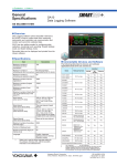
<<Contents>> <<Index>> General Specifications GA10 Data Logging Software GS 04L65B01-01EN Overview Data Logging Software GA10 (hereafter referred to as GA10) is used to collect data from measuring instruments and controllers via communication and monitor and record the collected data. GA10 has two setting modes for configuring data collection, monitoring, and recording: Simple Settings mode and Detail Settings mode. Recorded data can be displayed and printed from the Viewer software. Specifications Item Description Connectable Devices and Software The following table lists the devices and software applications that GA10 can connect to. Maximum number of simultaneous device connections 100 Maximum number of simultaneous client connections No limit (operation guaranteed up to 32 clients) Maximum number of simultaneous operation projects 30 Maximum number of device registrations 1000 Maximum number of project registrations 10000 DX1000N 2 Maximum number of user registrations 100 DX1000T Maximum number of clients that can run simultaneously on the same PC 1 Scan interval (when set to PC time) 100 ms, 200 ms, 500 ms, 1 s, 2 s, 5 s, 10 s, 20 s, 30 s, 1 min, 2 min, 5 min, 10 min GX10, GX20 GP10, GP20 R1.01 or later R2.01 or later DX2000 2 2 DX2000T 2 CX1000 CX2000 The scan interval of each device. Record interval (when set to PC time) 100 ms, 200 ms, 500 ms, 1 s, 2 s, 5 s, 10 s, 20 s, 30 s, 1 min, 2 min, 5 min, 10 min (limited to an integer multiple of the scan interval) Record interval (when set to device time) Same as the scan interval. Maximum number of recording channels (tags) 2000 Number of display groups 50 Number of channels (tags) per display group 50 Language English, Japanese, Chinese, French, German, Russian, Korean 1 Release Number DX1000 2 Scan interval (when set to device time) 1 Interface1 Name FX1000 MV1000 MV2000 μR10000 μR20000 R3.20 or later R1.11 or later R1.01 or later R1.31 or later RS422/485 Ethernet Yes Yes Yes Yes Yes Yes Yes Yes Yes Yes Yes Yes Yes Yes Yes Yes Yes Yes Yes Yes Yes Yes Yes Yes Yes Yes Yes Yes Yes Yes Yes Yes Yes Yes Yes Yes Yes Yes Yes Yes Yes Yes MX100 R3.01 or later No No Yes MW100 R3.01 or later No No Yes DA100 Models released on Nov., 2002 and later Yes Yes Yes DR130 Models released on Dec., 1999 and later Yes Yes Yes Yes Yes Yes Yes Yes Yes DR230 DR240 Make sure to use the same language setting for this software, Windows OS, and the recorders that data is to be collected from. R4.11 or later RS-232 •DR231/241 Released on Dec., 1999 and later •DR232/242 Released on Nov., 2002 and later DAQLOGGER R7.11 or later No No Yes DAQ32Plus R11.08 or later No No Yes MXLOGGER R2.07 or later Devices supporting the Modbus protocol 1 2 No No Yes Yes Yes Yes Yes: Supported No: Not supported When connecting GA10 to the DXAdvanced (DX1000, DX1000N, DX1000T, DX2000, DX2000T) with Security Function (/AS1) through the Ethernet interface, specify the access user to “Administrator.” Additionally, note that the “Administrator” who can login to the DX is limited to one administrator. Yokogawa Electric Corporation 2-9-32, Nakacho, Musashino-shi, Tokyo, 180-8750 Japan GS 04L65B01-01EN ©Copyright Jan. 2014 2nd Edition Feb.28, 2014 2 <<Contents>> <<Index>> Functions Configuration There two setting modes for configuring the software: Simple Settings and Detail Settings. The settings that you can configure in each mode is shown below. •Simple Settings mode: Devices to connect, collection and recording intervals, data file save destination •Detail Settings mode: Devices, tags, display groups, collect & monitor, recording, mail, access privileges, others Export/Import You can export/import a project, tag numbers, and tag comments in a server to use it. Monitoring The values of data being collected can be monitored from multiple clients. You can create display groups, each consisting of channels of multiple devices, and display vast amounts of collected data in an efficient manner. •Simple Settings mode: A fixed monitor page consisting of a trend display and digital display. •Detail Settings mode: Four types of displays (trend, digital, meter, and alarm) can be divided into up to 16 displays. You can arrange these displays for easy monitoring of data. Alarm Feature The alarm feature monitors alarms set on recorders and data loggers and notifies the user when alarms occur. •Alarm display: When an alarm occurs, the corresponding tag or group on the monitor page blinks in red. The indication returns to its original state when the alarm is cleared. •Alarm sound: The PC generates beeps when an alarm occurs. You can stop the beeping by clicking a button. •Alarm ACK: You can stop the blinking alarm display and reflect the alarm-acknowledged condition on the display. •Alarm log: The occurrence and clearance of alarms can be logged. Email sending GA10 can send email when alarms occur or when the communication status changes. Instantaneous values or alarm information can be attached on the email. •Support for SMTP Authentication / POP before SMTP •Conditions for sending email Alarm occurrence Disconnect/Recovery Specified period Specified time Data file created Data loss 2 Time modes The timestamp is selectable from PC time or Device time. PC time is the time information that the PC in which the server is installed uses. Device time is the time information that the data collection device uses. Recording Collected data can be recorded to the PC. Data can be saved to GA10 binary files or Excel files. Recording can be manually controlled or automatically started and stopped based on the following conditions: Specified time, specified period, alarm, level Viewer The universal viewer can display the following data generated by the recorder on the screen and print it out on the printer. •Viewer function Waveform display, digital display, circular display, list display, etc. •Data conversion: File conversion to ASCII or MS-Excel format Data supplementing function (Backfill function*) If a data dropout occurs in the data file that is being recorded due to a communication interference, this function automatically acquires data from the internal memory of the device and restores the data loss in the file. * Only available when the device time is used for the timestamp with GX/GP/DX/MV/FX1000. Data loss n tio ica n u ce mm ren Co erfe int Back-fills data on the main unit after communications are restored. All Rights Reserved. Copyright © 2014, Yokogawa Electric Corporation GS 04L65B01-01EN Feb.28, 2014-00 3 <<Contents>> <<Index>> Multilogging Log You can register multiple configurations (projects) and collect data at different times. Up to 1000 log events that occur from when the user logs in to the server until the user logs out are displayed. Additional Monitoring PCs (Clients) By installing GA10CL to other PCs connected to the network, you can control GA10 from and share collected data between multiple PCs. It is possible for multiple PCs to access a single GA10 simultaneously. DDE Server User Management Trial mode GA10 users are registered and managed on each server. There are two user levels: administrator and user. Administrators are responsible for registering and deleting all users. Users enter their IDs and passwords to access a server. Of the users registered in a server, only those that have been granted privileges can access projects. If a user is accessing a project, other users cannot access that project. GA10 has a trial mode in which 100 channels can be used for 60 days without a license. Administrator: Register and delete users Client Client Client Server access privileges Project operation privileges Server The DDE (Dynamic Data Exchange) server feature allows collected data to be loaded into Excel and other applications. GX/GP web application Online setting can be made using Web browser. For more information, please see General Specification (GS 04L51B01-01EN or GS 04L52B01-01EN.) Server and Client GA10 is a client-server software application.Users perform various server operations from a client. The server collects, records, and manages data received from connected devices on the basis of the instructions received from the client. The client function and server function are installed together in a single PC. You can also install GA10CL, which is a version that contains only the client function, in other PCs. Multiple clients can simultaneously access a single server. GA10 Project 1 Project 2 Project 3 GA10CL Operation Monitoring Data collection Instruction to the server Data collection and recording User The operation scope of each user can be managed by assigning one of four levels: owner, manager, operator, and monitor. The table below shows the available project access privilege types and their operation scope. Level Privilege Type Allowed Operations Operation Details 1 Owner All operations All operations (including deleting the project) Set project access privileges. 2 Manager Settings Operation Monitor Edit setup data. Start/stop data monitoring or recording. View recorded data files. Open data files. Delete data files. Monitor collected data. 3 Operator Operation Monitor View setup data. Start/stop data monitoring or recording. View recorded data files. Open data files. Delete data files. Monitor collected data. 4 Monitor Monitor View recorded data files. Open data files. Monitor collected data. All Rights Reserved. Copyright © 2014, Yokogawa Electric Corporation Client Response to the client Server Data collection Data Collection Project GA10 collects data in units of projects. Projects are created by users to suite their purposes. For example, a project named “Process A” can be created to collect measured data from a process called “A.” In this way, a project can be created for each set of collected data. For each project, the data to be collected, data to be recorded, the monitor page layout, and the like are specified. Multiple projects can be created in a single server. GS 04L65B01-01EN Feb.28, 2014-00 4 <<Contents>> <<Index>> System Structure GA10 is a software application that consolidates various devices connected over a network and performs data collection. GA10 can connect to YOKOGAWA recorders and data loggers. It can also collect data that has been acquired by YOKOGAWA’s data acquisition software (MXLOGGER, DAQLOGGER, and DAQ32Plus). Moreover, it supports the Modbus protocol, enabling data collection from YOKOGAWA’s control instruments (temperature controllers, signal conditioners, and power monitors). GA10 can also collect data from other manufacturers’ devices that support Modbus communication. Data Logging Software Server Converter Client Client Data collection ・・・ RS-232 Operation Data collection RS-422/485 Instruments supporting RS-422/485 communication Ethernet Data collection RS-232 Instruments supporting RS-232 communication Instruments supporting Ethernet communication MXLOGGER DAQLOGGER DAQ32Plus Source devices for MXLOGGER data collection Instruments supporting Modbus communication Source devices for DAQLOGGER data collection Source devices for DAQ32Plus data collection Example 1: 200 channels, 1 PC GA10-02 (200 ch) ・・・ GA10CL-01 GA10CL-01 GA10CL-01 GA10-05 (500 ch) 200 ch Example 2: 500 channels, 4 PCs ・・・ 500 ch All Rights Reserved. Copyright © 2014, Yokogawa Electric Corporation GS 04L65B01-01EN Feb.28, 2014-00 5 <<Contents>> <<Index>> PC System Requirements Additional Monitoring PCs (clients) Hardware Suffix Code Model Item Description GA10CL CPU Pentium 4, 3.2 GHz or faster Main memory 2 GB or more Hard disk 200 MB or more of free space Mouse Mouse compatible with OS Display 1024 x 768 dots or higher, 65536 colors or more Communication ports RS-232 or Ethernet port compatible with the OS To perform RS-232 communication or RS-422/485 communication with a connected device, the server PC needs a RS-232 serial port. Client license for GA10 Number of licenses -01 1 license -05 5 licenses -10 10 licenses -50 50 licenses Additional Channels Suffix Code Model GA10UP Edition Upgrade -01 100ch to 200ch, 200ch to 500ch, 500ch to 1000ch, 1000ch to 2000ch 32bit 64bit Service Pack -02 100ch to 500ch, 200ch to 1000ch, 500ch to 2000ch Yes No SP3 -03 100ch to 1000ch, 200ch to 2000ch -04 100ch to 2000ch Windows XP Home Edition Professional Yes No SP3 Windows Vista Home Premium Yes No SP2 Windows 7 Home Premium Yes Yes SP1 Professional Yes Yes SP1 — Yes Yes No SP Pro Yes Yes No SP Windows Server 2008 R2 No Yes SP1 Windows Server 2012 — No Yes No SP Windows 8 1 Make sure to use the same language setting for this software, Windows OS, and the recorders that data is to be collected from. Other Operating Environments Item Description Microsoft Office Excel 2007, 2010, 2013 Acrobat Reader Adobe Reader X (latest version recommended) RS-232 - RS-422/485 converter To perform RS-422/485 communication with a connected device, use a converter. (YOKOGAWA ML2 recommended) Model and Suffix Codes Model Suffix Code GA10 Number of channels Description Data Logging Software License -01 100 ch -02 200 ch -05 500 ch -10 1000 ch -20 2000 ch Description Channels upgrade license for GA10 Operating system OS1 Description All Rights Reserved. Copyright © 2014, Yokogawa Electric Corporation Subject to change without notice. How the software is provided Name Description License sheet Contains the license keys. Check that the correct number of licenses are present. GA10 Data Logging Software Downloading Software and Manuals 1 sheet (A4 size) Software Download the latest version from the following URL: www.smartdacplus.com/software/en/ User's Manual Product user's manuals can be downloaded or viewed at the following URL. To view the user's manual, you need to use Adobe Reader 7 or later by Adobe Systems. www.smartdacplus.com/manual/en/ Trademarks •SMARTDAC+ is a registered trademarks of Yokogawa Electric Corporation. •Microsoft, MS and Windows are registered trademarks of Microsoft Corporation USA. •Adobe and Acrobat are registered trademarks or trademarks of Adobe Systems Incorporated. •Pentium is a trademark of Intel Corporation in the United States and/or other countries. •Ethernet is a registered trademark of XEROX Corporation. •Modbus is a registered trademark of AEG Schneider. •Other company and/or product names are registered trade mark of their manufactures. •The company and product names used in this document are not accompanied by the registered trademark or trademark symbols (® and ™). GS 04L65B01-01EN Feb.28, 2014-00