1
User’s
Manual
WX1
GateWT
IM WX1-03E
8th Edition
This manual describes the functions and operations of GateWT. To ensure correct
use, please read this manual thoroughly before beginning operation. After reading
the manual, keep it in a convenient location for quick reference in the event a question
arises.
GateWT is a software program that acquires data from WT series instruments and
transfers it to DAQLOGGER or Remote Monitor.
Note
• The contents of this manual are subject to change without prior notice as a result of
continuing improvements to the software’s performance and functions.
• Every effort has been made in the preparation of this manual to ensure the accuracy
of its contents. However, should you have any questions or find any errors, please
contact your nearest YOKOGAWA representative as listed on the back cover of this
manual.
• Copying or reproducing all or any part of the contents of this manual without the
permission of Yokogawa Electric Corporation is strictly prohibited.
• Use of this product (software and this manual) on more than one computer at the
same time is prohibited. Use by more than one user is also prohibited.
• Transfer or lending of this product to any third party is prohibited.
• Yokogawa Electric Corporation provides no guarantees other than for physical
deficiencies found on the original disk or this manual upon opening the product
package.
• License numbers will not be reissued. Please keep the license number in a safe
place.
Copyrights
• Copyrights for the programs included on the CD-ROM are attributable to Yokogawa
Electric Corporation.
Trademarks
• DAQWORX, DAQLOGGER, and DAQEXPLORER are registered trademarks or
trademarks of Yokogawa Electric Corporation.
• Microsoft, Windows, and Windows Vista are registered trademarks or trademarks of
Microsoft Corporation in the United States and/or other countries.
• Adobe and Acrobat are registered trademarks or trademarks of Adobe Systems
Incorporated.
• Company and product names that appear in this manual are registered trademarks or
trademarks of their respective holders.
• The company and product names used in this manual are not accompanied by the
registered trademark or trademark symbols (® and ™).
Revisions
•
•
•
•
•
•
•
•
1st EditionJune 2003
2nd EditionFeburuary 2005
3rd EditionJune 2007
4th EditionJanuary 2009
5th EditionJune 2009
6th EditionJanuary 2011
7th EditionApril 2011
8th EditionOctober 2011
8th Edition : October 2011 (YK)
All Rights Reserved, Copyright © 2003 Yokogawa Electric Corporation
IM WX1-03E
Software License Agreement
IMPORTANT - PLEASE READ CAREFULLY BEFORE INSTALLING OR USING:
THANK YOU VERY MUCH FOR SELECTING SOFTWARE OF YOKOGAWA ELECTRIC CORPORATION ("YOKOGAWA"). BY INSTALLING OR OTHERWISE USING THE
SOFTWARE PRODUCT, YOU AGREE TO BE BOUND BY THE TERMS AND CONDITIONS OF THIS AGREEMENT. IF YOU DO NOT AGREE, DO NOT INSTALL NOR USE
THE SOFTWARE PRODUCT AND PROMPTLY RETURN IT TO THE PLACE OF PURCHASE FOR A REFUND, IF APPLICABLE.
Software License Agreement
1. Scope
This Agreement applies to the following software products and associated documentation of Yokogawa (collectively, "Software Product"). Unless otherwise provided by
Yokogawa, this Agreement applies to the updates and upgrades of the Software Product which may be provided by Yokogawa.
Software Product: DAQWORX (It is limited to each software that you bought).
2. Grant of License
2.1Subject to the terms and conditions of this Agreement, Yokogawa hereby grants to you a non-exclusive and non-transferable right to use the Software Product on a
single or, the following specified number of, computer(s) and solely for your internal operation use, in consideration of full payment by you to Yokogawa of the license fee
separately agreed upon.
Granted number of License: 1 (one)
2.2Unless otherwise agreed or provided by Yokogawa in writing, the following acts are prohibited:
a) to reproduce the Software Product, except for one archival copy for backup purpose, which shall be maintained with due care subject to this Agreement;
b)to sell, lease, distribute, transfer, pledge, sublicense, make available via the network or otherwise convey the Software Product or the license granted herein to any
other person or entity;
c) to use the Software Product on any unauthorized computer via the network;
d)to cause, permit or attempt to dump, disassemble, decompile, reverse-engineer, or otherwise translate or reproduce the Software Product into source code or other
human readable format, or to revise or translate the Software Product into other language and change it to other formats than that in which Yokogawa provided;
e) to cause, permit or attempt to remove any copy protection used or provided in the Software Product; or
f) to remove any copyright notice, trademark notice, logo or other proprietary notices or identification shown in the Software Product.
2.3Any and all technology, algorithms, know-how and process contained in the Software Product are the property or trade secret of Yokogawa or licensors to Yokogawa.
Ownership of and all the rights in the Software Product shall be retained by Yokogawa or the licensors and none of the rights will be transferred to you hereunder.
2.4You agree to maintain the aforementioned property and trade secret of Yokogawa or licensors and key codes in strict confidence, not to disclose it to any party other
than your employees, officers, directors or similar staff who have a legitimate need to know to use the Software Product and agreed in writing to abide by the obligations
hereunder.
2.5Upon expiration or termination of this Agreement, the Software Product and its copies, including extracts, shall be returned to Yokogawa and any copies retained in your
computer or media shall be deleted irretrievably. If you dispose of media in which the Software Product or its copy is stored, the contents shall be irretrievably deleted.
2.6The Software Product may contain software which Yokogawa is granted a right to sublicense or distribute by third party suppliers, including affiliates of Yokogawa ("Third
Party Software"). If suppliers of the Third Party Software ("Supplier") provide special terms and conditions for the Third Party Software which differ from this Agreement,
the special terms and conditions separately provided by Yokogawa shall prevail over this Agreement. Some software may be licensed to you directly by Supplier.
2.7The Software Product may contain open source software ("OSS"), for which the special terms and conditions separately provided by Yokogawa shall take precedence
over this Agreement.
3. Restrictions on Application
3.1Unless otherwise agreed in writing between you and Yokogawa, the Software Product is not intended, designed, produced or licensed for use in relation to aircraft
operation or control, ship navigation or marine equipment control, or ground facility or device for support of the aforesaid operation or control, or for use in relation to rail
facility, nuclear related facility, radiation-related equipment, or medical equipment or facility, or under any other circumstances which may require high safety standards.
3.2If the Software Product is used for the abovementioned purposes, neither Yokogawa nor Supplier assumes liability for any claim or damage arising from the said use
and you shall indemnify and hold Yokogawa, Supplier, their affiliates, subcontractors, officers, directors, employees and agents harmless from any liability or damage
whatsoever, including any court costs and attorney's fees, arising out of or related to the said use.
4. Limited Warranty
4.1The Software Product shall be provided to you on an "as is" basis at the time of delivery and except for physical damage to the recording medium containing the Software
Product, Yokogawa and Supplier shall disclaim all of the warranties whatsoever, express or implied, and all liabilities therefrom. If any physical defect is found on the
recording medium not later than twelve (12) months from delivery, Yokogawa shall replace such defective medium free of charge, provided that the defective medium
shall be returned to the service office designated by Yokogawa at your expense within the said twelve (12) months. THIS LIMITED WARRANTY PROVIDED IN THIS
CLAUSE IS IN LIEU OF ALL OTHER WARRANTIES OF ANY KIND WHATSOEVER AND YOKOGAWA HEREBY DISCLAIMS ALL OTHER WARRANTIES RELATING
TO THE SOFTWARE PRODUCT, WHETHER EXPRESSED OR IMPLIED, INCLUDING WITHOUT LIMITATION, ANY IMPLIED WARRANTIES OF MERCHANTABILITY,
FITNESS FOR ANY PARTICULAR PURPOSE, NON-INFRINGEMENT, QUALITY, FUNCTIONALITY, APPROPRIATENESS, ACCURACY, RELIABILITY AND RECENCY.
IN NO EVENT SHALL YOKOGAWA WARRANT THAT THERE IS NO INCONSISTENCY OR INTERFERENCE BETWEEN THE SOFTWARE PRODUCT AND OTHER
SOFTWARE NOR SHALL BE LIABLE THEREFOR. The warranty provisions of the applicable law are expressly excluded to the extent permitted.
4.2At the sole discretion of Yokogawa, Yokogawa may upgrade the Software Product to the new version number ("Upgrade") and make it available to you at your expense
or free of charge as Yokogawa deems fit. In no event shall Yokogawa be obliged to upgrade the Software Product or make the Upgrade available to you.
4.3Certain maintenance service may be available for some types of Software Product at Yokogawa's current list price. Scope and terms and conditions of the maintenance
service shall be subject to those separately provided by Yokogawa. Unless otherwise provided in Yokogawa catalogues or General Specifications, maintenance services
will be available only for the latest version and the immediately preceding version. In no event will service for the immediately preceding version be available for more than
5 years after the latest version has been released. In addition, no service will be provided by Yokogawa for the Software Product which has been discontinued for more
than 5 years. Notwithstanding the foregoing, maintenance service may not be available for non-standard Software Product. Further, in no event shall Yokogawa provide
any service for the Software Product which has been modified or changed by any person other than Yokogawa.
ii
IM WX1-03E
Software License Agreement
5. Infringement
5.1If you are warned or receive a claim by a third party that the Software Product in its original form infringes any third party's patent (which is issued at the time of delivery
of the Software Product), trade mark, copyright or other intellectual property rights ("Claim"), you shall promptly notify Yokogawa thereof in writing.
5.2If the infringement is attributable to Yokogawa, Yokogawa will defend you from the Claim at Yokogawa's expense and indemnify you from the damages finally granted by
the court or otherwise agreed by Yokogawa out of court. The foregoing obligation and indemnity of Yokogawa shall be subject to that i) you promptly notify Yokogawa of
the Claim in writing as provided above, ii) you grant to Yokogawa and its designees the full authority to control the defense and settlement of such Claim and iii) you give
every and all necessary information and assistance to Yokogawa upon Yokogawa's request.
5.3If Yokogawa believes that a Claim may be made or threatened, Yokogawa may, at its option and its expense, either a) procure for you the right to continue using the
Software Product, b) replace the Software Product with other software product to prevent infringement, c) modify the Software Product, in whole or in part, so that it
become non-infringing, or d) if Yokogawa believes that a) through c) are not practicable, terminate this Agreement and refund you the paid-up amount of the book value
of the Software Product as depreciated.
5.4Notwithstanding the foregoing, Yokogawa shall have no obligation nor liability for, and you shall defend and indemnify Yokogawa and its suppliers from, the Claim, if the
infringement is arising from a) modification of the Software Product made by a person other than Yokogawa, b) combination of the Software Product with hardware or
software not furnished by Yokogawa, c) design or instruction provided by or on behalf of you, d) not complying with Yokogawa's suggestion, or e) any other causes not
attributable to Yokogawa.
5.5This section states the entire liability of Yokogawa and its suppliers and the sole remedy of you with respect to any claim of infringement of a third party's intellectual
property rights. Notwithstanding anything to the contrary stated herein, with respect to the claims arising from or related to the Third Party Software or OSS, the special
terms and conditions separately provided for such Third Party Software or OSS shall prevail.
6. Limitation of Liability
6.1EXCEPT TO THE EXTENT THAT LIABILITY MAY NOT LAWFULLY BE EXCLUDED IN CONTRACT, YOKOGAWA AND SUPPLIERS SHALL NOT BE LIABLE TO ANY
PERSON OR LEGAL ENTITY FOR LOSS OR DAMAGE, WHETHER DIRECT, INDIRECT, SPECIAL, INCIDENTAL, CONSEQUENTIAL OR EXEMPLARY DAMAGES,
OR OTHER SIMILAR DAMAGES OF ANY KIND, INCLUDING WITHOUT LIMITATION, DAMAGES FOR LOSS OF BUSINESS PROFITS, BUSINESS INTERRUPTION,
LOSS OR DESTRUCTION OF DATA, LOSS OF AVAILABILITY AND THE LIKE, ARISING OUT OF THE USE OR INABILITY TO USE OF THE SOFTWARE PRODUCT,
OR ARISING OUT OF ITS GENERATED APPLICATIONS OR DATA, EVEN IF ADVISED OF THE POSSIBILITY OF SUCH DAMAGES, WHETHER BASED IN
WARRANTY (EXPRESS OR IMPLIED), CONTRACT, STRICT LIABILITY, TORT (INCLUDING NEGLIGENCE), OR ANY OTHER LEGAL OR EQUITABLE GROUNDS.
IN NO EVENT YOKOGAWA AND SUPPLIER'S AGGREGATE LIABILITY FOR ANY CAUSE OF ACTION WHATSOEVER (INCLUDING LIABILITY UNDER CLAUSE
5) SHALL EXCEED THE DEPRECIATED VALUE OF THE LICENSE FEE PAID TO YOKOGAWA FOR THE USE OF THE CONCERNED PART OF THE SOFTWARE
PRODUCT. If the Software Product delivered by Yokogawa is altered, modified or combined with other software or is otherwise made different from Yokogawa catalogues,
General Specifications, basic specifications, functional specifications or manuals without Yokogawa's prior written consent, Yokogawa shall be exempted from its
obligations and liabilities under this Agreement or law.
6.2Any claim against Yokogawa based on any cause of action under or in relation to this Agreement must be given in writing to Yokogawa within three (3) months after the
cause of action accrues.
7. Export Control
You agree not to export or provide to any other countries, whether directly or indirectly, the Software Product, in whole or in part, without prior written consent of Yokogawa.
If Yokogawa agrees such exportation or provision, you shall comply with the export control and related laws, regulations and orders of Japan, the United States of America,
and any other applicable countries and obtain export/import permit and take all necessary procedures under your own responsibility and at your own expense.
8. Audit; Withholding
8.1Yokogawa shall have the right to access and audit your facilities and any of your records, including data stored on computers, in relation to the use of the Software Product
as may be reasonably necessary in Yokogawa's opinion to verify that the requirements of this Agreement are being met.
8.2Even after license being granted under this Agreement, should there be any change in circumstances or environment of use which was not foreseen at the time of delivery
and, in Yokogawa's reasonable opinion, is not appropriate for using the Software Product, or if Yokogawa otherwise reasonably believes it is too inappropriate for you to
continue using the Software Product, Yokogawa may suspend or withhold the license provided hereunder.
9. Assignment
If you transfer or assign the Software Product to a third party, you shall expressly present this Agreement to the assignee to ensure that the assignee comply with this
Agreement, transfer all copies and whole part of the Software Product to the assignee and shall delete any and all copy of the Software Product in your possession
irretrievably. This Agreement shall inure to the benefit of and shall be binding on the assignees and successors of the parties.
10. Termination
Yokogawa shall have the right to terminate this Agreement with immediate effect upon notice to you, if you breach any of the terms and conditions hereof. Upon termination of
this Agreement, you shall promptly cease using the Software Product and, in accordance with sub-clause 2.5, return or irretrievably delete all copies of the Software Product,
certifying the same in writing. In this case the license fee paid by you for the Software Product shall not be refunded. Clauses 2.4 and 2.5, 3, 5, 6 and 11 shall survive any
termination of this Agreement.
11. Governing Law; Disputes
This Agreement shall be governed by and construed in accordance with the laws of Japan.
Any dispute, controversies, or differences which may arise between the parties hereto, out of, in relation to or in connection with this Agreement ("Dispute") shall be resolved
amicably through negotiation between the parties based on mutual trust. Should the parties fail to settle the Dispute within ninety (90) days after the notice is given from either
party to the other, the Dispute shall be addressed in the following manner:
(i) If you are a Japanese individual or entity, the Dispute shall be brought exclusively in the Tokyo District Court (The Main Court) in Japan.
(ii)If you are not a Japanese individual or entity, the Dispute shall be finally settled by arbitration in Tokyo, Japan in accordance with the Commercial Arbitration Rules
of the Japan Commercial Arbitration Association. All proceedings in arbitration shall be conducted in the English language, unless otherwise agreed. The award of
arbitration shall be final and binding upon both parties, however, each party may make an application to any court having jurisdiction for judgment to be entered on
the award and/or for enforcement of the award.
12. Miscellaneous
12.1 This Agreement supersedes all prior oral and written understandings, representations and discussions between the parties concerning the subject matter hereof to
the extent such understandings, representations and discussions should be discrepant or inconsistent with this Agreement.
12.2 If any part of this Agreement is found void or unenforceable, it shall not affect the validity of the balance of the Agreement, which shall remain valid and enforceable
according to its terms and conditions. The parties hereby agree to attempt to substitute for such invalid or unenforceable provision a valid or enforceable provision that
achieves to the greatest extent possible the economic, legal and commercial objectives of the invalid or unenforceable provision.
12.3 Failure by either party to insist on performance of this Agreement or to exercise a right when entitled does not prevent such party from doing so at a later time, either
in relation to that default or any subsequent one.
End of document
IM WX1-03E
iii
Overview of This Manual
Structure of This Manual
This user’s manual consists of the following chapters.
Chapter
1
Title
Overview
2
Operating Procedure
3
Detailed Description of
Functions
Index
Description
Gives an overview of the GateWT software.
Lists the PC requirements for running Gate-WT and
gives information about system configuration.
Gives procedures for entering environment and data
logging interval settings, and how to monitor the
operational status of the software.
Provides a detailed description of the functions of
GateWT. Lists error messages, their causes, and
their corrective actions.
An alphabetical index of the manual's contents.
Scope of This Manual
This manual does not explain the basic operations of your PC's operating system (OS).
For information regarding the basic operations of Windows, see the Windows user’s
manual.
Conventions Used in This Manual
• Units
K Denotes 1024.
M Denotes 1024K.
G Denotes 1024M.
Example: 10 KB
Example: 10 MB
Example: 2 GB
• Boldface Type
Hardware and software controls that the user manipulates such as dialog boxes,
buttons, and menu commands are often set in boldface type.
• Subheadings
On pages in chapters 1 through 3 that describe operating procedures, the following
subheadings are used to distinguish the procedure from their explanations.
Procedure
iv
Note
This subsection contains the operating procedure used to carry out
the function described in the current section. All procedures are
written with inexperienced users in mind; experienced users may
not need to carry out all the steps.
Calls attention to information that is important for proper operation
of the instrument.
IM WX1-03E
1
Contents
Software License Agreement............................................................................................................. ii
Overview of This Manual.................................................................................................................. iv
2
Chapter 1 Overview
1.1 Overview of GateWT Functions............................................................................................ 1-1
1.2 System Overview.................................................................................................................. 1-2
3
Chapter 2 Operating Procedure
2.1
2.2
2.3
2.4
2.5
2.6
Running and Exiting Gate-WT.............................................................................................. 2-1
Entering Environment Settings............................................................................................. 2-2
Connecting from DAQLOGGER or Remote Monitor............................................................ 2-7
Process Run/Stop and Service Run/Stop............................................................................. 2-8
Viewing the Status of the Executable Function.................................................................... 2-9
Viewing Version Information............................................................................................... 2-10
Chapter 3 Detailed Description of Functions
3.1 Overview............................................................................................................................... 3-1
Environment Setting Functions............................................................................................. 3-1
Executable Function............................................................................................................. 3-1
3.2 Detailed Description of Functions......................................................................................... 3-2
Serial Port............................................................................................................................. 3-2
GP-IB Communication.......................................................................................................... 3-2
Ethernet Communication...................................................................................................... 3-2
WT Settings.......................................................................................................................... 3-2
Automatic Model Determination............................................................................................ 3-3
Scan Interval......................................................................................................................... 3-3
Setting the Number of Retries.............................................................................................. 3-3
Port Settings......................................................................................................................... 3-4
Running/Stopping the Executable Function.......................................................................... 3-4
Monitor Server Function of the Executable Function............................................................ 3-4
Executable Function Status Display..................................................................................... 3-4
Test Acquisition..................................................................................................................... 3-4
Group and Channel Assignments......................................................................................... 3-5
Tag Settings........................................................................................................................ 3-17
Channel Names, Tag IDs, and Tag Names......................................................................... 3-25
Channel Colors................................................................................................................... 3-25
GateWT is started and the data of a possible data collection from WT1600...................... 3-26
GateWT is started and the data of a possible data collection from WT1800...................... 3-27
GateWT is started and the data of a possible data collection from WT500........................ 3-29
3.3 Error Messages and Corrective Actions............................................................................. 3-31
Error.................................................................................................................................... 3-31
Message............................................................................................................................. 3-31
Executable Function Messages.......................................................................................... 3-31
Index
IM WX1-03E
Index
Chapter 1
Overview
1.1
1
Overview of GateWT Functions
2
3
Index
Note
When connecting the GateWT and WT1600 and acquiring data, you must set the WT1600’s
measurement range to Fixed Range since data communication is not possible if it is set to Auto
Range.
Features
• Runs as a Windows application.
• Compatible with the following instruments: WT110, WT110E, WT130, WT200, WT210,
WT230, WT1010, WT1030, WT2010, WT2030, WT1030M, WT1600, WT1800 and
WT500.
• Up to 16 units of the WT100, WT200, WT1000, WT2000, WT1600, WT1800 or WT500
can be linked.
• Measurement can be performed at intervals of up to 0.5 seconds*.
* However, DAQLOGGER’s shortest interval is 1 second. Also, the maximum speed of 0.5
seconds may not be attainable depending on the amount of data being read, the response time
of the device, and the communication speed.
IM WX1-03E
Overview
GateWT is a software program that acquires data from WT series instruments and
transfers it to DAQLOGGER or Remote Monitor. Using GateWT allows you to monitor
data on DAQLOGGER or Remote Monitor that is measured on WT series instruments.
Yokogawa’s DAQLOGGER is a software program that allows users to open a connection
from their PC to various kinds of Yokogawa recorders (the mR, VR, DARWIN, DX, MV,
and CX) and perform data logging and monitoring.
Yokogawa’s Remote Monitor is a software program that enables monitoring of data
logged by recorders or data logging software.
1-1
1.2
System Overview
System
This software can connect with and download data from a WT series instrument having
the following characteristics.
However, the harmonic option is not supported.
• A WT110, WT110E, WT200, or WT210 with RS-232 or GP-IB communication
functions installed
• A WT230 or WT130 with RS-232 or GP-IB communication functions installed
• A WT1010, WT1030, WT1030M, WT2010, or WT2030 with RS-232 or GP-IB
communication functions installed
• A WT1600 with RS-232, GP-IB, or Ethernet functionality.
• A WT1800 with GP-IB or Ethernet functionality.
• A WT500 with GP-IB or Ethernet functionality.
Required Operating Systems
Run DAQWORX under any of the following operating systems.
• Windows 2000 Professional SP4
• Windows XP Home Edition SP3
• Windows XP Professional SP3 (excluding Windows XP Professional x64 Editions)
• Windows Vista Home Premium SP2 (excluding the 64-bit editions)
• Windows Vista Business SP2 (excluding the 64-bit editions)
• Windows 7 Home Premium, SP1 (32-bit and 64-bit editions)
• Windows 7 Professional, SP1 (32-bit and 64-bit editions)
The language displayed by the software under different language versions of the OS are
as follows.
OS Language
Japanese
Other
Software Language
Japanese
English
Hardware Requirements
The following hardware are required to use GateWT.
• PC:A PC that runs one of the OS above, and that meets the
following CPU and memory requirements.
When Using Windows 2000 or Windows XP
Pentium 4, 1.6 GHz or faster Intel x64 or x86 processor; 512 MB or more of memory
When Using Windows Vista
Pentium 4, 3 GHz or faster Intel x64 or x86 processor; 2 GB or more of memory
When Using Windows 7
32-bit edition: Intel Pentium 4, 3 GHz or faster x64 or x86 processor; 2 GB or more of memory
64-bit edition: Intel x64 processor that is equivalent to Intel Pentium 4, 3 GHz or faster; 2 GB or more of memory
• Free disk space: 200 MB or more
• Communication device: An Ethernet (when connecting to DAQLOGGER, Remote
Monitor, WT1600, WT1800 or WT500), RS-232, or GP-IB port
that is recognized by the operating system.
• CD-ROM drive:
Used to install the software
• Peripheral devices: A mouse supported by the operating system
1-2
IM WX1-03E
1.2 System Overview
1
Overview
• GP-IB port:Required for GP-IB communications between the software and
a WT series instrument
Please use the PCI-GPIB or PCMCIA-GPIB by National
Instruments.
A video card that is recommended for the OS and a display • Monitor:
that is supported by the OS, has a resolution of 1024×768 or higher, and that can show 65,536 colors (16-bit, high color) or more.
2
3
Index
IM WX1-03E
1-3
1.2 System Overview
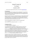
System Configuration
GateWT
TCP/IP connection
Monitor server protocol
Data transfer
Remote Monitor
Ethernet
It is recommended that you run GateWT and DAQLOGGER on separate PCs.
Software Configuration
GateWT
Displays execution
status
Environment setting
functions
DAQLOGGER
Writes to file
Status information
Executable
function
Environment
settings file
Ethernet
Ethernet
File read out
Serial , GP-IB,
or Ethernet
communications
Remote Monitor
WT series
instrument
GateWT Configurator consists of two separate software functions. The role of each
function within the configurator is as follows:
• Environment Setting Functions
These functions allow the user to enter various settings required by the executable
function for communications with the WT series instrument, as well as those required
for data transfers to and from DAQLOGGER and Remote Monitor. The user can also
view the execution status.
• Executable Function
The software reads data from the WT series instruments at fixed intervals. It also acts
as a monitor server, transferring data to DAQLOGGER and Remote Monitor.
1-4
IM WX1-03E
Chapter 2
2.1
Operating Procedure
1
Running and Exiting Gate-WT
Running the Software
2
Procedure
GateWT > GateWT.
Operating Procedure
1. From the Windows Start menu, choose Programs > YOKOGAWA DAQWORX >
3
The GateWT Configurator opens, displaying the user interface.
Index
Note
• When you start GateWT, it is restored to the same status that was active during the previous
session.
• If the program is closed while a process or service is running, the license will be considered to be “in use.”
If the message, “Invalid license number. Please reinstall.” appears when restarting the program, it may
indicate that the user is attempting to run a Gate program in excess of the number of available licenses.
Starting GateWT in Acquisition Start Mode
Procedure
1. From the Windows Start menu, choose Programs > YOKOGAWA DAQWORX >
GateWT > GateWT, then right-click GateWT and select Create Shortcut.
2. Right-click the shortcut icon and select Properties.
3. Choose the Shortcut tab, then add /START to the right of the path in the Target
box and click OK.
4. Choose the shortcut from the Windows Start menu. The connection status of the
previous session is restored, and acquisition begins.
Exiting the Software
Procedure
1. Choose File > Exit from the menu bar, or click the X button at the right end of the title bar.
IM WX1-03E
GateWT closes.
2-1
2.2
Entering Environment Settings
The following settings can be entered using the configurator.
• WT assignments, communications settings, and login settings
• Acquisition interval settings for each WT
• Port number settings (for the monitor server) as needed
• The settings can be saved.
Serial Port Settings
Procedure
1. Click the Serial Setting tab or choose View > Serial Setting from the menu bar.
The Serial Setting tab is displayed.
Click to display a list
Drag to select the
desired items
Copies the setting in the first item
of the selection to all of the items in the selection
Turns the selected items ON and OFF
2. Enter settings for each item.
2-2
Port number :
ON (blue)/OFF (gray)
Baud rate :
4800, 9600, 19200
Data length :
Fixed at 8
Parity :
Fixed at NONE
Stop bit :
Fixed at 1
IM WX1-03E
2.2 Entering Environment Settings
1
WT Settings
Procedure
1. Click the WT Setting tab or choose View > WT Setting from the menu bar.
2
The WT Setting tab is displayed.
Operating Procedure
3
Click to display a list
Index
Only the active COM ports
(specified in serial port settings)
are displayed
Click to display the Input
Address dialog box
2. Enter the communication method and address.
Communication type :
Select the port to be used for the connection. Only
the numbered COM ports turned ON in the serial
setting tab are displayed.
For GP-IB
Click a cell in the Address column to open the dialog box in the figure below.
Enter the GP-IB address.
For Ethernet (ETHER)
Click Address to display the following dialog box.
Enter the IP address or host name, user name (only WT1600), and password (only WT1600).
For Serial Ports Set to COM1–COM9 (RS-232 Ports)
An address is not entered.
IM WX1-03E
Address :
Only needed if the communication type is GP-IB.
2-3
2.2 Entering Environment Settings
Automatic Model Determination
3. Click Auto determination on the toolbar or choose Communication > Recorder
Model Determination from the menu bar.
Auto determination button
The following items are displayed.
Model :
The specific WT models to be connected.
Channel :
The number of channels on the WT to be connected.
Tag Settings
4. Double-click the tag number cell on the WT setting tab of the tag that you wish to set.
The Tag Setting dialog box opens.
Cannot be changed
(see chapter 3 regarding codes)
Choose the decimal place
Initial settings of the tag names are
assigned from information obtained during
automatic model determination
Enter the upper and lower limit
values of span (-1E16~1E16)
Click to display the Color
setting dialog box
Enter the units
Test results
displayed here
Drag to select a
range of items
Turns the selected items
ON and OFF
2-4
Copies the setting in the first
item of the selection to all of the
items in the selection
Restore the default
color to all tags
IM WX1-03E
2.2 Entering Environment Settings
1
Executing the Test
5. Click the Test Execution button in the Tag Setting dialog box.
The test result is displayed in the value column.
2
Stopping the Test
6. Click the Test Stop button.
3
Procedure
1. Click the Scan Interval Setting tab or choose View > Scan Interval Setting from
the menu bar.
Index
The Scan Interval Setting tab is displayed.
Scan Interval Settings
2. Specify a scan interval from 0.5 to 3600 seconds.
Setting the Number of Retries
3. Turn the communication retry setting ON or OFF.
4. Enter the time interval between retries.
The available setting range is 30 to 3600 seconds.
Port Settings
Procedure
1. Choose File > Port Number from the menu bar.
2. You can change the port number used by the monitor server.
IM WX1-03E
Operating Procedure
Scan Interval and Retry Settings
2-5
2.2 Entering Environment Settings
Saving Environment Settings
Procedure
1 Click the Save button on the tool bar or choose File > Save from the menu bar.
Save button
Test Acquisition
Procedure
1. Double-click a number in the GateWT Configurator.
The Tag Setting dialog box opens.
Double-click
Click
Test acquisition result
2. Click the Test Execute button.
2-6
The test acquisition result is displayed in the Value column.
IM WX1-03E
2.3
1
Connecting from DAQLOGGER or Remote
Monitor
3
In this case, system numbers are assigned as follows:
WT assigned to WT01 : 0
WT assigned to WT02 : 1
Index
Connecting from DAQLOGGER
Procedure
See section 2.6 of the WX101 DAQLOGGER WX81 DAQLOGGER Client Package
User’s Manual (IM WX101-01E).
Note
• If a connection is made with GateWT when DAQLOGGER’s system server setting is set to
No system number, the connected WTs are handled on the same system. For example,
if a GateWT with two WTs connected is set to No system number on DAQLOGGER,
DAQLOGGER handles both units channels as a single connected GateWT.
• When recorder model determination is performed by DAQLOGGER, models numbered 01
under GateWT’s “WT Setting” are displayed as No. 00. To identify models numbered 02 or
higher, specify the system number on DAQLOGGER. For example, for number 02, specify
01 under System No.
Connecting from Remote Monitor
Procedure
See section 8.1 of the WX101 DAQLOGGER WX81 DAQLOGGER Client Package
User’s Manual (IM WX101-01E), or section 9.2 of the WX102 DAQ32Plus WX82
DAQ32Plus Client Package User’s Manual (IM WX102-01E).
IM WX1-03E
2
Operating Procedure
While the executable function is running, DAQLOGGER or Remote Monitor works via
Ethernet to log and monitor the data that the WT is acquiring. GateWT’s executable
function acts as the client of a DAQLOGGER or Remote Monitor that is running as the
monitor server.
2-7
2.4
Process Run/Stop and Service Run/Stop
Running/Stopping from the Menu Bar
Procedure
Running as a Process or Service
1. Click the Service execution or Process execution button on the tool bar. Or,
choose Execute > Service or Execute > Process from the menu bar.
The executable function starts as a process or service. “Service” or “Process” is
displayed under Practice Status on the Practice Status tab.
Stop button
Process execution button
Service execution button
Note
• Service execution can only be specified by users with Administrator privileges.
• Services cannot be executed when using Windows Vista.
Stopping the Process or Service
1. Click the Stop button on the tool bar or choose Execute > Stop from the menu bar.
The Practice Status item shown on the Practice/Status tab displays “Stop.”
Running/Stopping the Executable Function from the Practice/Status Tab
Procedure
1. Click the Practice/Status tab or choose View > Practice/Status from the menu bar.
The Practice/Status tab is displayed.
Select the practice type
Running as a Process or Service
2. Select to execute the function as a process or service.
3. Click Practice.
The executable function starts, and “Service” or “Process” is displayed under
Practice Status.
Stopping the Process or Service
2. Click the Stop button.
2-8
“Stop” is displayed for the practice status.
IM WX1-03E
2.5
Viewing the Status of the Executable Function
Procedure
2
Displaying the Connection Status
Operating Procedure
1. Click the Execution/Status tab, or choose View > Execution/Status from the
menu bar.
1
3
The Execution/Status tab is displayed, allowing you to see the method under
which the executable function may be running (as a process or as a service),
whether or not it is running, and with which PCs communications are open.
Index
Displays the names
of connected clients
Double-click to display the
Error Indicator dialog box
Select the
practice type
Displays the communications status with the client
Gray: Stopped
Red: Error
Green: Normal
Viewing Error Detail
2. Double-click the box displaying the client communication status on the Execution/
Status tab (shown above).
The Error Indicator dialog box opens.
See section 3.3 for error messages.
Note
• If a warning message is displayed (code Wxxxx), the lamp that displays the connection
status by color does not blink red.
• When an error occurs and the lamp blinks red, the Error Indicator dialog box appears. If you
close the dialog box, the lamp turns green.
IM WX1-03E
2-9
2.6
Viewing Version Information
Procedure
1. Click the About button on the tool bar or choose Help > About from the menu bar.
About button
The Version dialog box opens.
Version
Company name
User name
License number
2-10
IM WX1-03E
Chapter 3
3.1
Detailed Description of Functions
1
Overview
GateWT opens communications with WT series instruments and acquires data at
regular intervals. Through the monitor server function, the acquired data is transferred
to DAQLOGGER or Remote Monitor via Ethernet. GateWT Configurator consists of two
separate software functions. The following is a list of the features of each software function.
3
Environment Setting Functions
Executable Function
Features of the executable function are as follows:
• Runs as a service
• Multiple instances of the function may not be run simultaneously
• Reads the settings file and connects with up to 16 WTs
Communication protocols: GP-IB, RS-232, Ethernet
• Reads instantaneous data from the WTs at fixed intervals and saves the data to
internal memory
Reading interval: 0.5 – 3600 seconds
The internal memory holds the 1800 most recent data samples.
• Runs as a monitor server
Compatible with the DAQLOGGER monitor server specifications.
• Provides a list of clients connected to the status display function
3-1
Detailed Description of Functions
Basically, the environment setting functions are used to enter all environment settings
required to run the executable function. The environment setting functions include the
following :
• Entry of parameters used for communications with up to 16 WTs.
Address
For GP-IB :
For serial communications :
Port, baud rate
For Ethernet :
IP address or host name, user name, password
• Display of information (model and number of channels) from the WTs to be connected
The software can open communication with the WTs and obtain this information automatically.
• Tag settings for each WT
• Use/Do not use (ON/OFF)
• Upper/lower limit of span
• Decimal place
• Unit
• Tag name
• Color
• Entry of the acquisition interval and port numbers for the executable function
• Test execution
• The above communication parameters, information from the WT, acquisition interval,
and port numbers can be saved
Later, this information can be loaded by the executable function.
• Runs/stops the executable function as a process
Two executable functions cannot be run at the same time.
If the function is already running as a service, it cannot be run as a process.
• Registers/deletes the executable function as a process
The function can run as a service while being registered.
It can be registered as an automatically executable service.
• Displays the status of the executable function
Stopped, running as a service, running as a process
• Displays a list of monitor clients connected with the executable function
• Displays errors from the executable function
Sockets are used for communication with the executable function.
IM WX1-03E
2
Index
3.2
Detailed Description of Functions
Serial Port
The communications ports available to GateWT are the COM1–COM9 serial (RS-232)
ports. The user must enter the following port settings.
• Use/Do not use (ON/OFF)
• Baud rate : Select 4800, 9600, or 19200
• Data length : Fixed at 8
• Parity : Fixed at NONE
• Stop bit : Fixed at 1
GP-IB Communication
GateWT can use GP-IB addresses 1–30.
Ethernet Communication
The WT1600, WT1800, and WT500 can perform Ethernet communications. Enter the IP
address or host name, user name (only WT1600), and password (only WT1600).
WT Settings
GateWT allows simultaneous connection with any combination of 16 of the following
instruments: WT110, WT110E, WT130, WT200, WT210, WT230, WT500, WT1010,
WT1030, WT1030M, WT1600, WT1800, WT2010, or WT2030.
The user must enter the following on the WTs to be accessed.
• Choose a communication method (COMx , GP-IB, or Ethernet)
For GP-IB
Communications mode :
488.2
Address :
1–30
For RS-232 (for instruments other than the WT1600)
Communications mode :
488.2
Handshaking :
0
Format :
0
Delimiter :
Cr + Lf
Baud rate :
4800, 9600, 19200
For RS-232 (WT1600)
Communication mode :
488.2
Handshaking :
CTS-RTS
Format :
8-NO-1
Delimiter :
Cr+Lf
Baud rate :
4800, 9600, 19200
For Ethernet : Enter the following settings.
When Using DHCP
Domain name
Primary DNS server address
Secondary DNS server address
Primary domain suffix
Secondary domain suffix
When Using DNS
IP address
Subnet mask
Default gateway
Note
When connecting with DAQLOGGER to acquire data from the WT, if the number of channels
set on the WT Setting tab exceeds 1600, 1600 channels of data is sent to DAQLOGGER,
starting with the first channel of the instrument of the smallest system number. Also, if an error
occurs on an instrument during the first communication and communication is restored by
executing a communication retry, connection is possible with that instrument in 1 scan mode
without any channels being cut out.
3-2
IM WX1-03E
3.2 Detailed Description of Functions
1
Automatic Model Determination
If you select a WT and perform automatic model determination, the model and number of
channels are passed to the WT Setting tab on the configurator.
However, harmonic option output for WT1600 and harmonic mode for WT1600 are not
supported.
2
Models and Number of Channels (Model Name in Brackets)
3
Number of channels
19
Detailed Description of Functions
Model
WT110 [253401]
WT110E [253451]
WT200 [253421]
WT210 [760401]
WT130 (2Elements) [253502]
WT230 (2Elements) [760502]
WT230 (3Elements) [253503]
WT230 (3Elements) [760503]
WT1010 [253610]
WT2010 [253101]
WT1030 (2Elements) [253620]
WT2030 (2Elements) [253102]
WT1030 (3Elements) [253630]
WT2030 (3Elements) [253103]
WT1030M [253640]
WT1600 (1Elements) [760101-01/-10]
WT1600 (1Elements) [760101-02/-11/-20]
WT1600 (1Elements) [760101-03/-12/-21/-30]
WT1600 (1Elements) [760101-04/-13/-22/-31/-40]
WT1600 (1Elements) [760101-05/-14/-23/-32/-41/-50]
WT1600 (1Elements) [760101-06/-15/-24/-33/-42/-51/-60]
WT1800 (1Elements) [WT1801-01/-10]
WT1800 (2Elements) [WT1802-02/-11/-20]
WT1800 (3Elements) [WT1803-03/-12/-21/-30]
WT1800 (4Elements) [WT1804-04/-13/-22/-31/-40]
WT1800 (5Elements) [WT1805-05/-14/-23/-32/-41/-50]
WT1800 (6Elements) [WT1806-06/-15/-24/-33/-42/-51/-60]
WT500[1Elements] (760201)
WT500[2Elements] (760202)
WT500[3Elements] (760203)
Index
53
70
18
46
61
68
76
123
170
197
224
251
55
104
104
179
205
254
99
156
213
* The number of WT500 channels given above is with the /G5 and /DS options. If an option
is not installed, the number of channels is decreased by the number of channels related to
that option. The number of WT1800 channels given above is with the /G5 or /G6, /DT, /MTR
or /AUX options. If an option is not installed, the number of channels is decreased by the
number of channels related to that option.
Scan Interval
A scan interval from 0.5 to 3600 seconds is selected for each of the 16 WTs.
Note
When connecting to DAQLOGGER and acquiring data from the WTs, if GateWT’s scan interval
is longer than that of DAQLOGGER, DAQLOGGER logs the same data repeatedly until the
next GateWT scan interval. Therefore, it is recommended that GateWT’s scan interval be set
to a value smaller than DAQLOGGER’s scan interval.
Setting the Number of Retries
The Retry function can be turned ON and OFF for each of the 16 WTs.
If Retry is turned ON, a retry interval of 30 to 3600 seconds can be specified.
Communication is reattempted each time the specified number of seconds elapses.
Retries are also performed on instruments with which a communication error occurred
during the first communication.
IM WX1-03E
3-3
3.2 Detailed Description of Functions
Port Settings
GateWT uses the following ports.
• Monitor server port
The port used for communications from DAQLOGGER and Remote Monitor.
• Status acquisition port
The port from which the status display software acquires status from the executable
software. Search for an empty port to use as the status acquisition port.
Running/Stopping the Executable Function
The user interface allows you to start and stop the executable function.
The executable function runs under one of the following two methods or “types.”
• Process Run/Stop
The executable function is run/stopped as a process.
• Service Run/Stop
The executable function is registered as an automatically executing service, then
run. After an executable function running as a service is stopped, its registration as a
service is deleted.
Note
As indicated by the service execution status, the executable function continues processing
even when the user has logged off of Windows. Also, the software is automatically run as a
service when the computer is turned ON. Service execution can only be specified by users
with Administrator privileges. Services cannot be executed when using Windows Vista.
Monitor Server Function of the Executable Function
When the executable function is running, you can connect from DAQLOGGER or
Remote Monitor via Ethernet using the remote monitor protocol, and acquire data. In this
case, system numbers are assigned as follows:
WT assigned to WT01 : 0
WT assigned to WT02 : 1
If GateWT is connected without specifying a system number on DAQLOGGER, all WTs
are regarded as being of the same system. For example, if a GateWT connected to two
WTs is connected to DAQLOGGER without specifying a system number, it appears as
though a single GateWT with two WTs worth of channels is connected.
Executable Function Status Display
The status display shows the status of the environment setting and executable functions.
The information from the executable function that can be displayed is as follows:
• Practice status (stopped, running as a service, running as a process)
• Connection status from the client
Displays a list of PCs running DAQLOGGERS and Remote Monitors with which the
executable software has opened a connection.
• Error display
Shows the presence or absence of errors on the executable function.
Test Acquisition
You can perform a test acquisition on each tag using the configurator. During the test
acquisition, data is read from WT output channels assigned to each tag and displayed
as digital values. This allows you to determine whether the communication settings for
each tag are correct. The test acquisition gets values from assigned tags at intervals of
approximately 1 second. Up to 32 tags can be assigned to a group, and up to 4 groups
can be displayed.
The number of tags that can be assigned to a group differs depending on the type of
connected device, and only up to 4 groups can be displayed.
3-4
IM WX1-03E
3.2 Detailed Description of Functions
1
Group and Channel Assignments
If connected from the remote monitor, the initial group and channel assignments are as
follows, and cannot be changed.
2
Note
If connected to GateWT using DAQLOGGER, the group and waveform assignments are
ignored.
3
WT100, WT110E [17]
Group String
Element1
Waveform Number
W01
W02
W03
W04
W05
W06
W07
W08
W09
W10
W11
W12
W13
W14
W15
W16
W17
W18
W19
Channel Assignment
V
A
W
VA
VAR
PF
DEGR
VHZ
AHZ
WH
WHP
WHM
AH
AHP
AHM
VPK
APK
MATH
TIME
Waveform Number
W01
W02
W03
W04
W05
W06
W07
W08
W09
W10
W11
W12
W13
W14
W15
W16
W17
W18
W19
Channel Assignment
V
A
W
VA
VAR
PF
DEGR
VHZ
AHZ
WH
WHP
WHM
AH
AHP
AHM
VPK
APK
MATH
TIME
Detailed Description of Functions
1 group
Index
WT200, WT210 [19]
2 group
IM WX1-03E
Group String
Element1
3-5
3.2 Detailed Description of Functions
WT130 (Three-phase, three-wire), WT230(Three-phase, three-wire) [53]
1 group
2 group
3 group
Group String
Element1
Element3
Sigma
Waveform Number
W01—W19
W01—W17
W01—W17
Channel Assignment
V—TIME (same as WT200)
V—APK
V—APK
WT130 (Three-phase, four-wire), WT230(Three-phase, four-wire) [70]
1 group
2 group
3 group
4 group
Group String
Element1
Element2
Element3
Sigma
Waveform Number
W01—W19
W01—W17
W01—W17
W01—W17
Channel Assignment
V—TIME (same as WT200)
V—APK
V—APK
V—APK
WT1010, WT2010 [18]
1 group
Group String
Element1
Waveform Number
W01
W02
W03
W04
W05
W06
W07
W08
W09
W10
W11
W12
W13
W14
W15
W16
W17
W18
Channel Assignment
V
A
W
VA
VAR
PF
DEGR
VPK
APK
WH
WHP
WHM
AH
AHP
AHM
FREQ
MATH
TIME
WT1030 (Three-phase, three-wire), WT2030(Three-phase, three-wire) [46]
1 group
2 group
3 group
Group String
Element1
Element3
Sigma
Waveform Number
W01—W18
W01—W15
W01—W15
Channel Assignment
V—TIME (same as WT1010)
V—AHM
V—AHM
WT1030(Three-phase, four-wire), WT2030(Three-phase, four-wire) [61]
1 group
2 group
3 group
4 group
Group String
Element1
Element2
Element3
Sigma
Waveform Number
W01—W18
W01—W15
W01—W15
W01—W15
Channel Assignment
V—TIME (same as WT1010)
V—AHM
V—AHM
V—AHM
WT1030M(Three-phase, four-wire)
1 group
2 group
3 group
4 group
5 group
3-6
Group String
Element1
Element2
Element3
Sigma
Motor
Waveform Number
W01—W18
W01—W15
W01—W15
W01—W15
W01
W02
W03
W04
W05
W06
W07
Channel Assignment
V—TIME (same as WT1010)
V—AHM
V—AHM
V—AHM
TORQ
RPM
SRPM
SLIP
MPOW
MEFF
TEFF
IM WX1-03E
3.2 Detailed Description of Functions
WT1600(1Element model)
1 group
IM WX1-03E
SigmaA
Waveform Number
W01
W02
W03
W04
W05
W06
W07
W08
W09
W10
W11
W12
W13
W14
W15
W16
W17
W18
W19
W20
W21
W22
W23
W24
W25
W26
W27
W01
W02
W03
W04
W05
W06
W07
W08
W09
W10
W11
W12
W13
W14
W15
W16
W17
W18
W19
W20
Channel Assignment
URMS
UMN
UDC
UAC
IRMS
IMN
IDC
IAC
P
S
Q
LAMBda
PHI
FU
FI
PC
UPPeak
UMPeak
IPPeak
IMPeak
TIME
WH
WHP
WHM
AH
AHP
AHM
URMS
UMN
UDC
UAC
IRMS
IMN
IDC
IAC
P
S
Q
LAMBda
PHI
PC
WH
WHP
WHM
AH
AHP
AHM
(Cont. on next page.)
3-7
1
2
3
Detailed Description of Functions
2 group
Group String
Element1
Index
3.2 Detailed Description of Functions
3 group
Group String
Other
4 group
Motor
Waveform Number
W01
W02
W03
W04
W05
W06
W07
W08
W09
W10
W11
W12
W13
W14
W15
W16
W17
W18
W19
W20
W21
W22
W01
W02
W03
W04
W05
W06
W07
Channel Assignment
ETA
SETA
F1
F2
F3
F4
DURMS1
DUMN1
DUDC1
DUAC1
DURMS2
DUMN2
DUDC2
DUAC2
DURMS3
DUMN3
DUDC3
DUAC3
DURMS4
DUMN4
DUDC4
DUAC4
TORQue
SPEed
SYNC
SLIP
PM
MEATa
MBETa
Waveform Number
W01—W27
W01—W27
W01—W20
W01—W20
W01—W22
W01—W07
Channel Assignment
URMS—AHM
URMS—AHM
URMS—AHM
URMS—AHM
ETA—DUAC4
TORQue—MBETa
Waveform Number
W01—W27
W01—W27
W01—W27
W01—W20
W01—W20
W01—W20
W01—W22
W01—W07
Channel Assignment
URMS—AHM
URMS—AHM
URMS—AHM
URMS—AHM
URMS—AHM
URMS—AHM
ETA—DUAC4
TORQue—MBETa
WT1600(2Elements model)
1 group
2 group
3 group
4 group
5 group
6 group
Group String
Element1
Element2
SigmaA
SigmaB
Other
Motor
WT1600(3Elements model)
1 group
2 group
3 group
4 group
5 group
6 group
7 group
8 group
3-8
Group String
Element1
Element2
Element3
SigmaA
SigmaB
SigmaC
Other
Motor
IM WX1-03E
3.2 Detailed Description of Functions
1
WT1600(4Elements model)
1 group
2 group
3 group
4 group
5 group
6 group
7 group
8 group
9 group
Group String
Element1
Element2
Element3
Element4
SigmaA
SigmaB
SigmaC
Other
Motor
Channel Assignment
URMS—AHM
URMS—AHM
URMS—AHM
URMS—AHM
URMS—AHM
URMS—AHM
URMS—AHM
ETA—DUAC4
TORQue—MBETa
Waveform Number
W01—W27
W01—W27
W01—W27
W01—W27
W01—W27
W01—W20
W01—W20
W01—W20
W01—W22
W01—W07
Channel Assignment
URMS—AHM
URMS—AHM
URMS—AHM
URMS—AHM
URMS—AHM
URMS—AHM
URMS—AHM
URMS—AHM
ETA—DUAC4
TORQue—MBETa
Waveform Number
W01—W27
W01—W27
W01—W27
W01—W27
W01—W27
W01—W27
W01—W20
W01—W20
W01—W20
W01—W22
W01—W07
Channel Assignment
URMS—AHM
URMS—AHM
URMS—AHM
URMS—AHM
URMS—AHM
URMS—AHM
URMS—AHM
URMS—AHM
URMS—AHM
ETA—DUAC4
TORQue—MBETa
2
3
Detailed Description of Functions
Waveform Number
W01—W27
W01—W27
W01—W27
W01—W27
W01—W20
W01—W20
W01—W20
W01—W22
W01—W07
WT1600(5Elements model)
1 group
2 group
3 group
4 group
5 group
6 group
7 group
8 group
9 group
10 group
Group String
Element1
Element2
Element3
Element4
Element5
SigmaA
SigmaB
SigmaC
Other
Motor
Index
WT1600(6Elements model)
1 group
2 group
3 group
4 group
5 group
6 group
7 group
8 group
9 group
10 group
11 group
IM WX1-03E
Group String
Element1
Element2
Element3
Element4
Element5
Element6
SigmaA
SigmaB
SigmaC
Other
Motor
3-9
3.2 Detailed Description of Functions
WT1800(1Element model)
1 group
3-10
Group String
Element1
2 group
ElemHrm1
(/G5, /G6)
3 group
Other
4 group
Motor (/MTR)
5 group
Aux (/AUX)
Waveform Number
W01
W02
W03
W04
W05
W06
W07
W08
W09
W10
W11
W12
W13
W14
W15
W16
W17
W18
W19
W20
W01
W02
W03
W04
W05
W06
W01
W02
W03
W04
W05
W06
W07
W08
W09
W10
W11
W12
W13
W14
W15
W16
W17
W18
W19
W20
W21
W22
W23
W24
W01
W02
W03
W04
W05
W01
W02
Channel Assignment
URMS
UMN
UDC
IRMS
IMN
IDC
P
S
Q
LAMBDA
PHI
FU
FI
TIME
WH
WHP
WHM
AH
AHP
AHM
UK_1
UK_T
IK_1
IK_T
UTHD
ITHD
ETA1
ETA2
ETA3
ETA4
F1
F2
F3
F4
F5
F6
F7
F8
F9
F10
F11
F12
F13
F14
F15
F16
F17
F18
F19
F20
SPEED
TORQUE
SYNCSP
SLIP
PM
AUX1
AUX2
IM WX1-03E
3.2 Detailed Description of Functions
Note
WT1800(2Elements model)
IM WX1-03E
1 group
2 group
3 group
4 group
5 group
Group String
Element1
Element2
ElemHrm1
ElemHrm2
SigmaA
6 group
7 group
Other
DeltaA (/DT)
8 group
9 group
Motor
Aux
Waveform Number
W01—W20
W01—W20
W01—W06
W01—W06
W01
W02
W03
W04
W05
W06
W07
W08
W09
W10
W11
W12
W13
W14
W01—W24
W01
W02
W03
W04
W05
W06
W07
W08
W09
W01—W05
W01—W02
Channel Assignment
URMS—AHM
URMS—AHM
UK_1—ITHD
UK_1—ITHD
URMS
UMN
IRMS
IMN
P
S
LAMBDA
PHI
WH
WHP
WHM
AH
AHP
AHM
ETA1—F20
DU1
DU2
DU3
DUS
DI
DP1
DP2
DP3
DPS
SPEED—PM
3-11
1
2
3
Detailed Description of Functions
• Since the maximum number of parameters that can be acquired via communications on the
WT1800 is 255, all functions cannot be acquired on GateWT. To acquire functions not in the
table, you can set them in the WT1800's user-defined functions (F1 to F20).
• (/G5, /G6) can be selected on instruments with the harmonic measurement functions option,
(/DT) can be selected on instruments with the delta computation functions option, (/MTR)
can be selected on instruments with the motor evaluation functions option and (/AUX) can
be selected on instruments with the auxiliary input measurement functions option. If an
instrument without an option is selected, the group numbers shift to fill in the missing option.
For example, groups are assigned as follows for a 2-element model with (/G5) and (/Aux)
but without (/DT), (/MTR).
Group 1:
Element1
Group 2:
Element2
Group 3:
ElemHrm1
Group 4:
ElemHrm2
Group 5:
SigmaA
Group 6:
Other
Group 7:
Aux
Index
3.2 Detailed Description of Functions
WT1800(3Elements model)
1 group
2 group
3 group
4 group
5 group
6 group
7 group
8 group
9 group
10 group
11 group
Group String
Element1
Element2
Element3
ElemHrm1
ElemHrm2
ElemHrm3
SigmaA
Other
DeltaA
Motor
Aux
Waveform Number
W01—W20
W01—W20
W01—W20
W01—W06
W01—W06
W01—W06
W01—W14
W01—W24
W01—W09
W01—W05
W01—W02
Channel Assignment
URMS—AHM
URMS—AHM
URMS—AHM
UK_1—ITHD
UK_1—ITHD
UK_1—ITHD
URMS—AHM
ETA1—F20
DU1—DPS
SPEED—PM
AUX1—AUX2
Waveform Number
W01—W20
W01—W20
W01—W20
W01—W20
W01—W06
W01—W06
W01—W06
W01—W06
W01—W14
W01—W14
W01—W24
W01—W09
W01—W09
W01—W05
W01—W02
Channel Assignment
URMS—AHM
URMS—AHM
URMS—AHM
URMS—AHM
UK_1—ITHD
UK_1—ITHD
UK_1—ITHD
UK_1—ITHD
URMS—AHM
URMS—AHM
ETA1—F20
DU1—DPS
DU1—DPS
SPEED—PM
AUX1—AUX2
Waveform Number
W01—W20
W01—W20
W01—W20
W01—W20
W01—W20
W01—W06
W01—W06
W01—W06
W01—W06
W01—W06
W01—W14
W01—W14
W01—W24
W01—W09
W01—W09
W01—W05
W01—W02
Channel Assignment
URMS—AHM
URMS—AHM
URMS—AHM
URMS—AHM
URMS—AHM
UK_1—ITHD
UK_1—ITHD
UK_1—ITHD
UK_1—ITHD
UK_1—ITHD
URMS—AHM
URMS—AHM
ETA1—F20
DU1—DPS
DU1—DPS
SPEED—PM
AUX1—AUX2
WT1800(4Elements model)
1 group
2 group
3 group
4 group
5 group
6 group
7 group
8 group
9 group
10 group
11 group
12 group
13 group
14 group
15 group
Group String
Element1
Element2
Element3
Element4
ElemHrm1
ElemHrm2
ElemHrm3
ElemHrm4
SigmaA
SigmaB
Other
DeltaA
DeltaB
Motor
Aux
WT1800(5Elements model)
1 group
2 group
3 group
4 group
5 group
6 group
7 group
8 group
9 group
10 group
11 group
12 group
13 group
14 group
15 group
16 group
17 group
3-12
Group String
Element1
Element2
Element3
Element4
Element5
ElemHrm1
ElemHrm2
ElemHrm3
ElemHrm4
ElemHrm5
SigmaA
SigmaB
Other
DeltaA
DeltaB
Motor
Aux
IM WX1-03E
3.2 Detailed Description of Functions
1
WT1800(6Elements model)
IM WX1-03E
Waveform Number
W01—W20
W01—W20
W01—W20
W01—W20
W01—W20
W01—W20
W01—W06
W01—W06
W01—W06
W01—W06
W01—W06
W01—W06
W01—W14
W01—W14
W01—W14
W01—W24
W01—W09
W01—W09
W01—W09
W01—W05
W01—W02
Channel Assignment
URMS—AHM
URMS—AHM
URMS—AHM
URMS—AHM
URMS—AHM
URMS—AHM
UK_1—ITHD
UK_1—ITHD
UK_1—ITHD
UK_1—ITHD
UK_1—ITHD
UK_1—ITHD
URMS—AHM
URMS—AHM
URMS—AHM
ETA1—F20
DU1—DPS
DU1—DPS
DU1—DPS
SPEED—PM
AUX1—AUX2
2
3
Detailed Description of Functions
1 group
2 group
3 group
4 group
5 group
6 group
7 group
8 group
9 group
10 group
11 group
12 group
13 group
14 group
15 group
16 group
17 group
18 group
19 group
20 group
21 group
Group String
Element1
Element2
Element3
Element4
Element5
Element6
ElemHrm1
ElemHrm2
ElemHrm3
ElemHrm4
ElemHrm5
ElemHrm6
SigmaA
SigmaB
SigmaC
Other
DeltaA
DeltaB
DeltaC
Motor
Aux
Index
3-13
3.2 Detailed Description of Functions
WT500(1Element model)
3-14
1 group
Group String
Element1
2 group
ElemHrm1(G5)
Waveform Number
W01
W02
W03
W04
W05
W06
W07
W08
W09
W10
W11
W12
W13
W14
W15
W16
W17
W18
W19
W20
W21
W22
W23
W24
W25
W26
W27
W28
W29
W30
W31
W32
W01
W02
W03
W04
W05
W06
W07
W08
W09
W10
W11
W12
W13
W14
W15
W16
W17
W18
W19
W20
W21
W22
W23
W24
W25
Channel Assignment
URMS
UMN
UDC
URMN
UAC
IRMS
IMN
IDC
IRMN
IAC
P
S
Q
LAMBda
PHI
FU
FI
UPPeak
UMPeak
IPPeak
IMPeak
CFU
CFI
TIME
WH
WHP
WHM
AH
AHP
AHM
WS
WQ
UK_0
UK_1
UK_T
IK_0
IK_1
IK_T
PK_0
PK_1
PK_T
SK_0
SK_1
SK_T
QK_0
QK_1
QK_T
LAMBDA0
LAMBDA1
LAMBDAT
PHIK_1
PHIK_T
PHIUk3
PHIIk3
UTHD
ITHD
PTHD
(Cont. on next page.)
IM WX1-03E
3.2 Detailed Description of Functions
3 group
Group String
Sigma
Other
5 group
Delta
(DT)
6 group
Phase
(G5)
1
Channel Assignment
URMS
UMN
UDC
URMN
UAC
IRMS
IMN
IDC
IRMN
IAC
P
S
Q
LAMBda
PHI
WH
WHP
WHM
AH
AHP
AHM
WS
WQ
ETA1
ETA2
F1
F2
F3
F4
F5
F6
F7
F8
DELTA1
DELTA2
DELTA3
DELTA4
P_U1U2
P_U1U3
P_U1I1
P_U1I2
P_U1I3
2
3
Detailed Description of Functions
4 group
Waveform Number
W01
W02
W03
W04
W05
W06
W07
W08
W09
W10
W11
W12
W13
W14
W15
W16
W17
W18
W19
W20
W21
W22
W23
W01
W02
W03
W04
W05
W06
W07
W08
W09
W10
W01
W02
W03
W04
W01
W02
W03
W04
W05
Index
Note
• With the WT500, because the maximum number of parameters that can be acquired via
communications is 255, the following cannot be acquired with the GateWT: 2nd through 50th
orders of U/I/P/S/Q/LAMBda/PHI; 1st, 2nd, and 4th through 50th orders of PHIU/PHII; and
UHDF, IHDF, and PHDF.
• (G5) can be selected on instruments with the harmonic option, and (DT) can be selected on
instruments with the delta option. If an instrument without an option is selected, the group
numbers shift to fill in the missing option. For example, groups are assigned as follows for a
1-element model with (G5) but without (DT).
Group 1:
Element1
Group 2:
ElemHrm1
Group 3:
Sigma
Group 4:
Other
Group 5:
Phase
IM WX1-03E
3-15
3.2 Detailed Description of Functions
WT500(2Elements model)
1 group
2 group
3 group
4 group
5 group
6 group
7 group
8 group
Group String
Element1
Element2
ElemHrm1
ElemHrm2
Sigma
Other
Delta
Phase
Waveform Number
W01—W32
W01—W32
W01—W25
W01—W25
W01—W23
W01—W10
W01—W04
W01—W05
Channel Assignment
URMS—WQ
URMS—WQ
UK_0—PTHD
UK_0—PTHD
URMS—WQ
ETA1—F8
DELTA1—DELTA4
P_U1U2—P_U1I3
Waveform Number
W01—W32
W01—W32
W01—W32
W01—W25
W01—W25
W01—W25
W01—W23
W01—W10
W01—W04
W01—W05
Channel Assignment
URMS—WQ
URMS—WQ
URMS—WQ
UK_0—PTHD
UK_0—PTHD
UK_0—PTHD
URMS—WQ
ETA1—F8
DELTA1—DELTA4
P_U1U2—P_U1I3
WT500(3Elements model)
1 group
2 group
3 group
4 group
5 group
6 group
7 group
8 group
9 group
10 group
3-16
Group String
Element1
Element2
Element3
ElemHrm1
ElemHrm2
ElemHrm3
Sigma
Other
Delta
Phase
IM WX1-03E
3.2 Detailed Description of Functions
1
Tag Settings
Initial settings of the tags are assigned according to the model information obtained
during automatic model determination.
WT100/WT200
WT110
WT110E
WT200
WT210
WT130(2Element)
WT230(2Element)
Group 1
(Group name: Element1)
Element1(V, A, W, VA, VAR, PF, DEGR,
VHZ, AHZ, WH, WHP, WHM, AH, AHP,
AHM)+MATH+TIME
Group 1
(Group name: Element1)
Group 2
(Group name: Element3)
Group 3
(Group name: Sigma)
Group 1
(Group name: Element1)
Group 2
(Group name: Element2)
Group 3
(Group name: Element3)
Group 4
(Group name: Sigma)
Element1(V–APK)+MATH+TIME
WT1010
WT2010
Group 1
(Group name: Element1)
WT1030
WT2030
Group 1
(Group name: Element1)
Group 2
(Group name: Element3)
Group 3
(Group name: Sigma)
Group 1
(Group name: Element1)
Group 2
(Group name: Element2)
Group 3
(Group name: Element3)
Group 4
(Group name: Sigma)
Group 1
(Group name: Element1)
Group 2
(Group name: Element2)
Group 3
(Group name: Element3)
Group 4
(Group name: Sigma)
Group 5
(Group name: Sigma)
Element1 (V, A, W, VA, PF, DEGR, VPK,
APK, WH, WHP, WHM, AH, AHP, AHM)+
FREQ+MATH+TIME
Element1(V–AHM)+FREQ+MATH+TIME
3
Detailed Description of Functions
WT130(3Element)
WT230(3Element)
Element3(V–APK)
Index
Sigma(V–APK)
Element1(V–APK)+MATH+TIME
Element2(V–APK)
Element3(V–APK)
Sigma(V–APK)
WT1000/WT2000
WT1030(3Element)
WT2030(3Element)
WT1030M
IM WX1-03E
2
Element3(V–AHM)
Sigma(V~AHM)
Element1(V–AHM)+FREQ+MATH+TIME
Element2(V–AHM)
Sigma(V–AHM)
Sigma(V–AHM)
Element1(V–AHM)+FREQ+MATH+TIME
Element2(V–AHM)
Element3(V–AHM)
Sigma(V–AHM)
TORQ, RPM, SRPM, SLIP, MPOW,
MEFF, TEFF
3-17
3.2 Detailed Description of Functions
WT1600
Tags set to group ElementX are the same as those for Element1. Tags set to group
SigmaX are the same as those for SigmaA.
Note
Since the maximum number of parameters that can be acquired via communications by the
WT1600 is 255, GateWT cannot acquire Cfu, Chi, FfU, FfI, Z, Rs, Xs, Rp, or Xp.
WT1600 (1Element)
Groupe 1
(Groupe Name:Element1)
Groupe 2
(SigmaA)
Groupe 3
(Other)
WT1600 (2Elements)
WT1600 (3Elements)
WT1600 (4Elements)
WT1600 (5Elements)
WT1600 (6Elements)
3-18
Groupe 4
(Motor)
Groupe 1 (Element1)
Groupe 2 (Element2)
Groupe 3 (SigmaA)
Groupe 4 (SigmaB)
Groupe 5 (Other)
Groupe 6 (Motor)
Groupe 1 (Element1)
Groupe 2 (Element2)
Groupe 3 (Element3)
Groupe 4 (SigmaA)
Groupe 5 (SigmaB)
Groupe 6 (SigmaC)
Groupe 7 (Other)
Groupe 8 (Motor)
Groupe 1 (Element1)
Groupe 2 (Element2)
Groupe 3 (Element3)
Groupe 4 (Element4)
Groupe 5 (SigmaA)
Groupe 6 (SigmaB)
Groupe 7 (SigmaC)
Groupe 8 (Other)
Groupe 9 (Motor)
Groupe 1 (Element1)
Groupe 2 (Element2)
Groupe 3 (Element3)
Groupe 4 (Element4)
Groupe 5 (Element5)
Groupe 6 (SigmaA)
Groupe 7 (SigmaB)
Groupe 8 (SigmaC)
Groupe 9 (Other)
Groupe 10 (Motor)
Groupe 1 (Element1)
Groupe 2 (Element2)
Groupe 3 (Element3)
Groupe 4 (Element4)
Groupe 5 (Element5)
Groupe 6 (Element6)
Groupe 7 (SigmaA)
Groupe 8 (SigmaB)
Groupe 9 (SigmaC)
Groupe 10 (Other)
Groupe 11 (Motor)
Element1(URMS, UMN, UDC, UAC, IRMS, IMN, IDC, IAC, P,
S, Q, LAMBda, PHI, FU, FI, PC, UPPeak, UMPeak, IPPeak,
IMPeak, TIME, WH, WHP, WHM, AH, AHP, AHM)
SigmaA(URMS, UMN, UDC, UAC, IRMS, IMN, IDC, IAC, P, S, Q,
LAMBda, PHI, PC, WH, WHP, WHM, AH, AHP, AHM)
Other(ETA, SETA, F1, F2, F3, F4, DURMS1, DUMN1, DUDC1,
DUAC1, DURMS2, DUDC2, DUAC2, DUMN2, DURM3, DUMN3,
DUDC3, DUAC3, DIRM, DIMN, DIDC, DIAC)
Motor(TORQue, SPEed, SYNC, SLIP, PM, MAETa, MBETa)
Element1(URMS—AHM)
Element2(URMS—AHM)
SigmaA(URMS—AHM)
SigmaB(URMS—AHM)
Other(ETA—DIAC)
Motor(TORQue—MBETa)
Element1(URMS—AHM)
Element2(URMS—AHM)
Element3(URMS—AHM)
SigmaA(URMS—AHM)
SigmaB(URMS—AHM)
SigmaC(URMS—AHM)
Other(ETA—DIAC)
Motor(TORQue—MBETa)
Element1(URMS—AHM)
Element2(URMS—AHM)
Element3(URMS—AHM)
Element4(URMS—AHM)
SigmaA(URMS—AHM)
SigmaB(URMS—AHM)
SigmaC(URMS—AHM)
Other(ETA—DIAC)
Motor(TORQUA—MBETa)
Element1(URMS—AHM)
Element2(URMS—AHM)
Element3(URMS—AHM)
Element4(URMS—AHM)
Element5(URMS—AHM)
SigmaA(URMS—AHM)
SigmaB(URMS—AHM)
SigmaC(URMS—AHM)
Other(ETA—DIAC)
Motor(TORQue—MBETa)
Element1(URMS—AHM)
Element2(URMS—AHM)
Element3(URMS—AHM)
Element4(URMS—AHM)
Element5(URMS—AHM)
Element6(URMS—AHM)
SigmaA(URMS—AHM)
SigmaB(URMS—AHM)
SigmaC(URMS—AHM)
Other(ETA—DIAC)
Motor(TORQue—MBETa)
IM WX1-03E
3.2 Detailed Description of Functions
WT1800
Tags set to group ElementX are the same as those for Element1. Tags set to group
ElemHrmX are the same as those for ElemHrm1. Tags set to group SigmaX are the
same as those for SigmaA. Tags set to group DeltaX are the same as those for DeltaA.
WT1800 (1Element)
WT1800 (3Elements)
WT1800 (4Elements)
IM WX1-03E
Groupe 4 (Motor)
Groupe 5 (Aux)
Groupe 1 (Element1)
Groupe 2 (Element2)
Groupe 3 (ElemHrm1)
Groupe 4 (ElemHrm2)
Groupe 5 (SigmaA)
Groupe 6 (Other)
Groupe 7 (DeltaA)
Groupe 8 (Motor)
Groupe 5 (Aux)
Groupe 1 (Element1)
Groupe 2 (Element2)
Groupe 3 (Element3)
Groupe 4 (ElemHrm1)
Groupe 5 (ElemHrm2)
Groupe 6 (ElemHrm3)
Groupe 7 (SigmaA)
Groupe 8 (Other)
Groupe 9 (DeltaA)
Groupe 10 (Motor)
Groupe 11 (Aux)
Groupe 1 (Element1)
Groupe 2 (Element2)
Groupe 3 (Element3)
Groupe 4 (Element4)
Groupe 5 (ElemHrm1)
Groupe 6 (ElemHrm2)
Groupe 7 (ElemHrm3)
Groupe 8 (ElemHrm4)
Groupe 9 (SigmaA)
Groupe 10 (SigmaB)
Groupe 11 (Other)
Groupe 12 (DeltaA)
Groupe 13 (DeltaB)
Groupe 14 (Motor)
Groupe 15 (Aux)
Element1 (URMS, UMN, UDC, IRMS, IMN, IDC, P, S, Q,
LAMBDA, PHI, FU, FI, TIME, WH, WHP, WHM, AH, AHP, AHM)
ElemHrm1 (UK_1, UK_T, IK_1, IK_T, UTHD, ITHD)
Other (ETA1, ETA2, ,ETA3, ETA4, F1, F2, F3, F4, F5, F6, F7, F8,
F9, F10, F11, F12, F13, F14, F15, F16, F17, F18, F19, F20)
Motor (SPEED, TORQUE, SYNCSP, SLIP, PM)
Aux (AUX1, AUX2)
Element1 (URMS—AHM)
Element2 (URMS—AHM)
ElemHrm1 (UK_1—ITHD)
ElemHrm2 (UK_1—ITHD)
SigmaA (URMS, UMN, IRMS, IMN, P, S, LAMBDA, PHI, WH,
WHP, WHM, AH, AHP, AHM)
Other (ETA1—F20)
DeltaA (DU1, DU2, DU3, DUS, DI, DP1, DP2, DP3, DPS)
Motor (SPEED—PM)
Aux (AUX1—AUX2)
Element1 (URMS—AHM)
Element2 (URMS—AHM)
Element3 (URMS—AHM)
ElemHrm1 (UK_1—ITHD)
ElemHrm2 (UK_1—ITHD)
ElemHrm3 (UK_1—ITHD)
SigmaA (URMS—AHM)
Other (ETA1—F20)
DeltaA (DU1—DPS)
Motor (SPEED—PM)
Aux (AUX1—AUX2)
Element1 (URMS—AHM)
Element2 (URMS—AHM)
Element3 (URMS—AHM)
Element4 (URMS—AHM)
ElemHrm1 (UK_1—ITHD)
ElemHrm2 (UK_1—ITHD)
ElemHrm3 (UK_1—ITHD)
ElemHrm4 (UK_1—ITHD)
SigmaA (URMS—AHM)
SigmaB (URMS—AHM)
Other (ETA1—F20)
DeltaA (DU1—DPS)
DeltaB (DU1—DPS)
Motor (SPEED—PM)
Aux (AUX1—AUX2)
(Cont. on next page.)
3-19
2
3
Detailed Description of Functions
WT1800 (2Elements)
Groupe 1
(Groupe Name:Element1)
Groupe 2 (ElemHrm1)
Groupe 3 (Other)
1
Index
3.2 Detailed Description of Functions
WT1800 (5Elements)
WT1800 (6Elements)
3-20
Groupe 1 (Element1)
Groupe 2 (Element2)
Groupe 3 (Element3)
Groupe 4 (Element4)
Groupe 5 (Element5)
Groupe 6 (ElemHrm1)
Groupe 7 (ElemHrm2)
Groupe 8 (ElemHrm3)
Groupe 9 (ElemHrm4)
Groupe 10 (ElemHrm5)
Groupe 11 (SigmaA)
Groupe 12 (SigmaB)
Groupe 13 (Other)
Groupe 14 (DeltaA)
Groupe 15 (DeltaB)
Groupe 16 (Motor)
Groupe 17 (Aux)
Groupe 1 (Element1)
Groupe 2 (Element2)
Groupe 3 (Element3)
Groupe 4 (Element4)
Groupe 5 (Element5)
Groupe 6 (Element6)
Groupe 7 (ElemHrm1)
Groupe 8 (ElemHrm2)
Groupe 9 (ElemHrm3)
Groupe 10 (ElemHrm4)
Groupe 11 (ElemHrm5)
Groupe 12 (ElemHrm6)
Groupe 13 (SigmaA)
Groupe 14 (SigmaB)
Groupe 15 (SigmaC)
Groupe 16 (Other)
Groupe 17 (DeltaA)
Groupe 18 (DeltaB)
Groupe 19 (DeltaC)
Groupe 20 (Motor)
Groupe 21 (Aux)
Element1 (URMS—AHM)
Element2 (URMS—AHM)
Element3 (URMS—AHM)
Element4 (URMS—AHM)
Element5 (URMS—AHM)
ElemHrm1 (UK_1—ITHD)
ElemHrm2 (UK_1—ITHD)
ElemHrm3 (UK_1—ITHD)
ElemHrm4 (UK_1—ITHD)
ElemHrm5 (UK_1—ITHD)
SigmaA (URMS—AHM)
SigmaB (URMS—AHM)
Other (ETA1—F20)
DeltaA (DU1—DPS)
DeltaB (DU1—DPS)
Motor (SPEED—PM)
Aux (AUX1—AUX2)
Element1 (URMS—AHM)
Element2 (URMS—AHM)
Element3 (URMS—AHM)
Element4 (URMS—AHM)
Element5 (URMS—AHM)
Element6 (URMS—AHM)
ElemHrm1 (UK_1—ITHD)
ElemHrm2 (UK_1—ITHD)
ElemHrm3 (UK_1—ITHD)
ElemHrm4 (UK_1—ITHD)
ElemHrm5 (UK_1—ITHD)
ElemHrm6 (UK_1—ITHD)
SigmaA (URMS—AHM)
SigmaB (URMS—AHM)
SigmaC (URMS—AHM)
Other (ETA1—F20)
DeltaA (DU1—DPS)
DeltaB (DU1—DPS)
DeltaC (DU1—DPS)
Motor (SPEED—PM)
Aux (AUX1—AUX2)
IM WX1-03E
3.2 Detailed Description of Functions
1
WT500
Tags set to group ElementX are the same as those for Element1.
Note
WT500 (1Element)
WT500 (2Elements)
WT500 (3Elements)
IM WX1-03E
Group 1
(Group name:Element1)
Group 2
(ElemHrm1)
(G5)
Group 3
(Sigma)
Group 4
(Other)
Group 5
(Delta)
(DT)
Group 6
(Phase)
(G5)
Group 1 (Element1)
Group 2 (Element2)
Group 3 (ElemHrm1)
(G5)
Group 4 (ElemHrm2)
(G5)
Group 5 (Sigma)
Group 6 (Other)
Group 7 (Delta)
(DT)
Group 8 (Phase)
(G5)
Group 1 (Element1)
Group 2 (Element2)
Group 3 (Element3)
Group 4 (ElemHrm1)
(G5)
Group 5 (ElemHrm2)
(G5)
Group 6 (ElemHrm3)
(G5)
Group 7 ( Sigma)
Group 8 (Other)
Group 9 (Delta)
(DT)
Group 10 (Phase)
(G5)
Element1(URMS, UMN, UDC, URMN, UAC, IRMS, IMN, IDC, IRMN,
IAC, P, S, Q, LAMBda, PHI, FU, FI, UPPeak, UMPeak, IPPeak,
IMPeak, CFU, CFI, TIME, WH, WHP, WHM, AH, AHP, AHM, WS, WQ)
Element1(UK_0, UK_1, UK_T, IK_0, IK_1, IK_T, PK_0, PK_1,
PK_T, SK_0, SK_1, SK_T, QK_0, QK_1, QK_T, LAMBD0, LAMBD1,
LAMBDT, PHIK_1, PHIK_T, PHIUk3, PHIIk3, UTHD, ITHD, PTHD)
SigmaA(URMS, UMN, UDC, URMN, UAC, IRMS, IMN, IDC, IRMN,
IAC, P, S, Q, LAMBda, PHI, WH, WHP, WHM, AH, AHP, AHM, WS, WQ)
Other(ETA1, ETA2, F1, F2, F3, F4, F5, F6, F7, F8)
Delta(DELTA1, DELTA2, DELTA3, DELTA4)
Phase(P_U1U2, P_U1U3, P_U1I1, P_U1I2, P_U1I3)
Element1(URMS—WQ)
Element2(URMS—WQ)
Element1(UK_0—PTHD)
Element2(UK_0—PTHD)
Sigma(URMS—WQ)
Other(ETA—F8)
Delta(DELTA1—DELTA4)
Phase(P_U1U2—P_U1I3)
Element1(URMS—WQ)
Element2(URMS—WQ)
Element3(URMS—WQ)
Element1(UK_0—PTHD)
Element2(UK_0—PTHD)
Element3(UK_0—PTHD)
Sigma(URMS—WQ)
Other(ETA—F8)
Delta (DELTA1—DELTA4)
Phase (P_U1U2—P_U1I3)
3-21
2
3
Detailed Description of Functions
• With the WT500, because the maximum number of parameters that can be acquired via
communications is 255, the following cannot be acquired with the GateWT: 2nd through 50th
orders of U/I/P/S/Q/LAMBda/PHI; 1st, 2nd, and 4th through 50th orders of PHIU/PHII; and
UHDF, IHDF, and PHDF.
• (G5) can be selected on instruments with the harmonic option, and (DT) can be selected on
instruments with the delta option. If an instrument without an option is selected, the group
numbers shift to fill in the missing option. For example, groups are assigned as follows for a
1-element model with (G5) but without (DT).
Group 1:
Element1
Group 2:
ElemHrm1
Group 3:
Sigma
Group 4:
Other
Group 5:
Phase
Index
3.2 Detailed Description of Functions
A list of function names used in this manual and function names used on
the WT1600 (Numerical display header name)
Function names used
in this manual
URMS
UMN
UDC
UAC
IRMS
IMN
IDC
IAC
P
S
Q
LAMBda
PHI
FU
FI
UPPeak
UMPeak
IPPeak
IMPeak
CFU
CFI
FFU
FFI
Z
RS
XS
RP
XP
3-22
: Function names used on the
WT1600 (Numerical display
header name)
: Urms
: Umean
: Udc
: Uac
: Irms
: Imean
: Idc
: Iac
:P
:S
:Q
:λ
:φ
: FreqU (fU)
: FreqI (fI)
: U+peak (U+pk)
: U-peak (U-pk)
: I+peak (I+pk)
: I-peak (I-pk)
: CfU
: CfI
: FfU
: FfI
:Z
: Rs
: Xs
: Rp
: Xp
Function names used : Function names used on the
in this manual WT1600 (Numerical display
header name)
PC : Pc
TIME : I-Time
WH : Wp
WHP : Wp+
WHM : WpAH : q
AHP : q+
AHM : qETA : η
SETA : 1/η
F1 : F1
F2 : F2
F3 : F3
F4 : F4
DURMS : ∆Urms
DUMN : ∆Umean
DUDC : ∆Udc
DUAC : ∆Uac
DIRMS : ∆Irms
DIMN : ∆Imean
DIDC : ∆Idc
DIAC : ∆Iac
SPEed : Speed
TORQue : Torque
SYNC : SyncSpd
SLIP : Slip
PM : Pm
MAETa : ηmA
IM WX1-03E
3.2 Detailed Description of Functions
A list of function names used in this manual and function names used on
the WT1800 (Numerical display header name)
Function names used
in this manual
IM WX1-03E
Function names used : Function names used on the
in this manual WT1800 (Numerical display
header name)
F4 : F4
F5 : F5
F6 : F6
F7 : F7
F8 : F8
F9 : F9
F10 : F10
F11 : F11
F12 : F12
F13 : F13
F14 : F14
F15 : F15
F16 : F16
F17 : F17
F18 : F18
F19 : F19
F20 : F20
DU1 : ∆U1
DU2 : ∆U2
DU3 : ∆U3
DUS : ∆UΣ
DI : ∆I
DP1 : ∆P1
DP2 : ∆P2
DP3 : ∆P3
DPS : ∆PΣ
TORQUE : Torque
SPEED : Speed
SYNCSP : Syncsp
SLIP : Slip
PM : Pm
AUX1 : Aux1
AUX2 : Aux2
3-23
2
3
Detailed Description of Functions
URMS
UMN
UDC
IRMS
IMN
IDC
P
S
Q
LAMBDA
PHI
FU
FI
TIME
WH
WHP
WHM
AH
AHP
AHM
UK_1
UK_T
IK_1
IK_T
UTHD
ITHD
ETA1
ETA2
ETA3
ETA4
F1
F2
F3
: Function names used on the
WT1800 (Numerical display
header name)
: Urms
: Umn
: Udc
: Irms
: Imn
: Idc
:P
:S
:Q
:λ
:φ
: fU (FreqU)
: fI (FreqI)
: Time
: WP
: Wp+
: Wp:q
: q+
: q: U(1)
: U(Total)
: I(1)
: I(Total)
: Uthd
: Ithd
: η1
: η2
: η3
: η4
: F1
: F2
: F3
1
Index
3.2 Detailed Description of Functions
A list of function names used in this manual and function names used on
the WT500 (Numerical display header name)
Function names used in
this manual
URMS
UMN
UDC
URMN
UAC
IRMS
IMN
IDC
IRMN
IAC
P
S
Q
LAMBda
PHI
FU
FI
UPPeak
UMPeak
IPPeak
IMPeak
CFU
CFI
TIME
WH
WHP
WHM
AH
AHP
AHM
WS
WQ
UK_0
UK_1
UK_T
IK_0
IK_1
IK_T
PK_0
PK_1
PK_T
SK_0
SK_1
SK_T
QK_0
QK_1
QK_T
LAMBD0
LAMBD1
LAMBDT
PHIK_1
PHIK_T
PHIUk3
PHIIk3
UTHD
ITHD
PTHD
3-24
: Function names used on
the WT500 (Numerical
display header name)
: Urms
: Umn
: Udc
: Urmn
: Uac
: Irms
: Imn
: Idc
: Irmn
: Iac
: P
: S
: Q
: λ
: φ
: FreqU(fU)
: FreqI(fI)
: U+peak(U+pk)
: U-peak(U-pk)
: I+peak(I+pk)
: I-peak(I-pk)
: CfU
: CfI
: Time
: WP
: WP+
: WP–
: q
: q+
: q–
: WS
: WQ
: U(k) k=0
: U(k) k=1
: U(k) k=Total
: I(k) k=0
: I(k) k=1
: I(k) k=Total
: P(k) k=0
: P(k) k=1
: P(k) k=Total
: S(k) k=0
: S(k) k=1
: S(k) k=Total
: Q(k) k=0
: Q(k) k=1
: Q(k) k=Total
: λ(k) k=0
: λ(k) k=1
: λ(k) k=Total
: φ(k) k=1
: φ(k) k=Total
: φU(k) k=3
: φI(k) k=3
: Uthd
: Ithd
: Pthd
Function names used in : Function names used on
this manual
the WT500 (Numerical
display header name)
ETA1 : η1
ETA2 : η2
F1 : F1
F2 : F2
F3 : F3
F4 : F4
F5 : F5
F6 : F6
F7 : F7
F8 : F8
DELTA1 : ∆F1
DELTA2 : ∆F2
DELTA3 : ∆F3
DELTA4 : ∆F4
P_U1U2 : φUi-Uj
P_U1U3 : φUi-Uk
P_U1I1 : φUi-Ii
P_U1I2 : φUi-Ij
P_U1I3 : φUi-Ik
IM WX1-03E
3.2 Detailed Description of Functions
1
Channel Names, Tag IDs, and Tag Names
GateWT’s default channel names and tag IDs are the same: EI:V, EI:A, … etc.
The tag names are the names of the output items on the connected WT: TAG01, TAG02,
…etc. These can be changed.
2
Note
When connecting DAQLOGGER to GateWT, channel names and tag IDs are ignored. You can
download tag names using tag setting software.
The default channel colors on GateWT are the following 16 colors.
Red, Green, Blue, Magenta, Orange, Cyan, Brown, LightGray, Purple, Pink, Yellow,
White, CaditBlue, LightPink, LightGreen, Salmon
These can be changed.
IM WX1-03E
3-25
Detailed Description of Functions
Channel Colors
3
Index
3.2 Detailed Description of Functions
GateWT is started and the data of a possible data collection from WT1600
GateWT doesn’t correspond to “Harmonic component mode.” Therefore, the data
collection of the parameter in the harmonic component mode is not made.
Element
Element
Element
Element
Element
Element
1
2
3
4
5
6
Voltage RMS
Voltage MEAN
URMS
UMN
URMS
UMN
URMS
UMN
URMS
UMN
URMS
UMN
URMS
UMN
Voltage DC
UDC
UDC
UDC
UDC
UDC
UDC
Voltage AC
Current RMS
UAC
IRMS
UAC
IRMS
UAC
IRMS
UAC
IRMS
UAC
IRMS
UAC
IRMS
Current MEAN
IMN
IMN
IMN
IMN
IMN
IMN
Current DC
IDC
IDC
IDC
IDC
IDC
IDC
Current AC
Active power
Apparent power
Reactive power
Power factor
Phase difference
Voltage frequency
Current frequency
Corrected Power Pc
Voltage + peak
Voltage – peak
Current + peak
Current – peak
Integration time
Watt hour
(positive and negative)
Watt hour (positive)
Watt hour (negative)
Current hour
(positive and negative)
Current hour (positive)
Current hour (negative)
IAC
P
S
Q
IAC
P
S
Q
IAC
P
S
Q
IAC
P
S
Q
IAC
P
S
Q
IAC
P
S
Q
Delta computation
voltage MEAN
Delta computation
voltage DC
Delta computation
current AC
Delta computation
current AC IRMS
Delta computation
current AC IMN
Delta computation
current AC IDC
Delta computation
current AC IAC
Efficiency 1
Efficiency 2
User-defined function 1
User-defined function 2
User-defined function 3
User-defined function 4
3-26
ΣA
ΣB
ΣC
motor
URMS URMS URMS TORQue
UMN
UMN
UMN
SPEed
Revolution
sped
UDC
UDC
UDC
SYNC
Synchronization
speed
UAC
UAC
UAC
SLIP
IRMS IRMS IRMS PM
Motor output
IMN
IMN
IMN
MAETa
Motor efficiency
IDC
IDC
IDC
MBETa
total efficiency
IAC
IAC
IAC
P
P
P
S
S
S
Q
Q
Q
LAMBda LAMBda LAMBda LAMBda LAMBda LAMBda LAMBda LAMBda LAMBda
PHI
FU
FI
PC
PHI
FU
FI
PC
PHI
FU
FI
PC
PHI
FU
FI
PC
PHI
FU
FI
PC
PHI
FU
FI
PC
UPPeak
UPPeak
UPPeak
UPPeak
UPPeak
UPPeak
PHI
PHI
PHI
PC
PC
PC
UMPeak UMPeak UMPeak UMPeak UMPeak UMPeak
IPPeak
IPPeak
IPPeak
IPPeak
IPPeak
IPPeak
IMPeak
IMPeak
IMPeak
IMPeak
IMPeak
IMPeak
TI
WH
TI
WH
TI
WH
TI
WH
TI
WH
TI
WH
WH
WH
WH
WHP
WHM
AH
WHP
WHM
AH
WHP
WHM
AH
WHP
WHM
AH
WHP
WHM
AH
WHP
WHM
AH
WHP
WHM
AH
WHP
WHM
AH
WHP
WHM
AH
AHP
AHM
DURM
DUMN
AHP
AHM
DURM
DUMN
AHP
AHM
DURM
DUMN
AHP
AHM
AHP
AHM
AHP
AHM
AHP
AHM
AHP
AHM
AHP
AHM
DUDC
DUDC
DUDC
DUAC
DUAC
DUAC
DIRMS
DIMN
DIDC
DIAC
ETA
SETA
F1
F2
F3
F4
IM WX1-03E
3.2 Detailed Description of Functions
1
GateWT is started and the data of a possible data collection from WT1800
ΣB
ΣC
motor
URMS
URMS
URMS
URMS
UMN
UMN
UMN
UMN
UMN
SPEED
Revolution
speed
TORQUE
UDC
UDC
UDC
IRMS
IMN
IRMS
IMN
IRMS
IMN
IRMS
IMN
IRMS
IMN
IRMS
IMN
IRMS
IMN
IDC
P
S
Q
IDC
P
S
Q
IDC
P
S
Q
IDC
P
S
Q
P
S
P
S
P
S
Element
Element
Element
Element
Element
1
2
3
4
5
6
Voltage RMS
URMS
URMS
URMS
URMS
URMS
Voltage MEAN
UMN
UMN
UMN
UMN
Voltage DC
UDC
UDC
UDC
Current RMS
Current MEAN
IRMS
IMN
IRMS
IMN
Current DC
Active power
Apparent power
Reactive power
Power factor
Phase difference
Voltage frequency
Current frequency
Integration time
Watt hour
(positive and negative)
Watt hour (positive)
Watt hour (negative)
Current hour
(positive and negative)
Current hour (positive)
Current hour (negative)
Rms voltage value of
harmonic order 1
Total harmonic voltage
Rms current value of
harmonic order 1
Total harmonic current
Total harmonic voltage
distortion
Total harmonic current
distortion
IDC
P
S
Q
IDC
P
S
Q
Equation for efficiency 1
Equation for efficiency 2
Equation for efficiency 3
Equation for efficiency 4
User-defined function 1
User-defined function 2
User-defined function 3
User-defined function 4
User-defined function 5
User-defined function 6
User-defined function 7
User-defined function 8
User-defined function 9
User-defined function 10
User-defined function 11
User-defined function 12
User-defined function 13
User-defined function 14
ETA1
ETA2
ETA3
ETA4
F1
F2
F3
F4
F5
F6
F7
F8
F9
F10
F11
F12
F13
F14
2
SYNCSP
Synchronization
speed
SLIP
PM
Motor output
LAMBDA LAMBDA LAMBDA LAMBDA LAMBDA LAMBDA LAMBDA LAMBDA LAMBDA
PHI
FU
FI
TIME
WH
PHI
FU
FI
TIME
WH
PHI
FU
FI
TIME
WH
PHI
FU
FI
TIME
WH
PHI
FU
FI
TIME
WH
PHI
FU
FI
TIME
WH
PHI
PHI
PHI
WH
WH
WH
WHP
WHM
AH
WHP
WHM
AH
WHP
WHM
AH
WHP
WHM
AH
WHP
WHM
AH
WHP
WHM
AH
WHP
WHM
AH
WHP
WHM
AH
WHP
WHM
AH
AHP
AHM
UK_1
AHP
AHM
UK_1
AHP
AHM
UK_1
AHP
AHM
UK_1
AHP
AHM
UK_1
AHP
AHM
UK_1
AHP
AHM
AHP
AHM
AHP
AHM
UK_T
IK_1
UK_T
IK_1
UK_T
IK_1
UK_T
IK_1
UK_T
IK_1
UK_T
IK_1
IK_T
UTHD
IK_T
UTHD
IK_T
UTHD
IK_T
UTHD
IK_T
UTHD
IK_T
UTHD
ITHD
ITHD
ITHD
ITHD
ITHD
ITHD
(Cont. on next page.)
IM WX1-03E
3-27
3
Detailed Description of Functions
ΣA
Element
Index
3.2 Detailed Description of Functions
User-defined function 15
User-defined function 16
User-defined function 17
User-defined function 18
User-defined function 19
User-defined function 20
Delta computation
voltage 1
Delta computation
voltage 2
Delta computation
voltage 3
Delta computation
voltage sigma
Delta computation
current
Delta computation
power 1
Delta computation
power 2
Delta computation
power 3
Delta computation
power sigma
Aux1
Aux2
3-28
F15
F16
F17
F18
F19
F20
DU1
DU2
DU3
DUS
DI
DP1
DP2
DP3
DPS
AUX1
AUX2
IM WX1-03E
3.2 Detailed Description of Functions
1
GateWT is started and the data of a possible data collection from WT500
Element1
URMS
UMN
UDC
URMN
UAC
IRMS
IMN
IDC
IRMN
IAC
P
S
Q
LAMBda
PHI
FU
FI
UPPeak
UMPeak
IPPeak
IMPeak
CFU
CFI
TIME
WH
WHP
WHM
AH
AHP
AHM
WS
WQ
UK_0
UK_1
UK_T
IK_0
IK_1
IK_T
PK_0
PK_1
PK_T
SK_0
SK_1
SK_T
QK_0
QK_1
QK_T
LAMBD0
LAMBD1
LAMBDT
PHIK_1
PHIK_T
PHIUk3
Element2
URMS
UMN
UDC
URMN
UAC
IRMS
IMN
IDC
IRMN
IAC
P
S
Q
LAMBda
PHI
FU
FI
UPPeak
UMPeak
IPPeak
IMPeak
CFU
CFI
TIME
WH
WHP
WHM
AH
AHP
AHM
WS
WQ
UK_0
UK_1
UK_T
IK_0
IK_1
IK_T
PK_0
PK_1
PK_T
SK_0
SK_1
SK_T
QK_0
QK_1
QK_T
LAMBD0
LAMBD1
LAMBDT
PHIK_1
PHIK_T
PHIUk3
Element3
URMS
UMN
UDC
URMN
UAC
IRMS
IMN
IDC
IRMN
IAC
P
S
Q
LAMBda
PHI
FU
FI
UPPeak
UMPeak
IPPeak
IMPeak
CFU
CFI
TIME
WH
WHP
WHM
AH
AHP
AHM
WS
WQ
UK_0
UK_1
UK_T
IK_0
IK_1
IK_T
PK_0
PK_1
PK_T
SK_0
SK_1
SK_T
QK_0
QK_1
QK_T
LAMBD0
LAMBD1
LAMBDT
PHIK_1
PHIK_T
PHIUk3
PHIIk3
PHIIk3
PHIIk3
UTHD
ITHD
PTHD
UTHD
ITHD
PTHD
UTHD
ITHD
PTHD
Σ
URMS
UMN
UDC
URMN
UAC
IRMS
IMN
IDC
IRMN
IAC
P
S
Q
LAMBda
PHI
2
3
Detailed Description of Functions
Voltage RMS
Voltage MEAN
Voltage DC
Voltage RMEAN
Voltage AC
Current RMS
Current MEAN
Current DC
Current RMEAN
Current AC
Active power
Apparent power
Reactive power
Power factor
Phase difference
Voltage frequency
Current frequency
Voltage + peak
Voltage – peak
Current + peak
Current – peak
Voltage crest factor
Current crest factor
Integration time
Watt hour (positive and negative)
Watt hour (positive)
Watt hour (negative)
Current hour (positive and negative)
Current hour (positive)
Current hour (negative)
Volt-ampare hours
Var hours
Rms voltage value of harmonic order 0
Rms voltage value of harmonic order 1
Total harmonic voltage
Rms current value of harmonic order 0
Rms current value of harmonic order 1
Total harmonic current
Active power of harmonic order 0
Active power of harmonic order 1
Total harmonic active power
Apparent power of harmonic order 0
Apparent power of harmonic order 1
Total harmonic apparent power
Reactive power of harmonic order 0
Reactive power of harmonic order 1
Total harmonic reactive power
Power factor of harmonic order 0
Power factor of harmonic order 1
Total harmonic power factor
Phase difference of harmonic order 1
Total harmonic phase difference
Phase difference between fundamental
signal voltage and harmonic order 3
Phase difference between fundamental
signal current and harmonic order 3
Total harmonic voltage distortion
Total harmonic current distortion
Total harmonic active power distortion
Index
WH
WHP
WHM
AH
AHP
AHM
WS
WQ
(Cont. on next page.)
IM WX1-03E
3-29
3.2 Detailed Description of Functions
Equation for efficiency 1
Equation for efficiency 2
User-defined function 1
User-defined function 2
User-defined function 3
User-defined function 4
User-defined function 5
User-defined function 6
User-defined function 7
User-defined function 8
Delta computation 1
Delta computation 2
Delta computation 3
Delta computation 4
Phase difference UIU2
Phase difference UIU3
Phase difference UII1
Phase difference UII2
Phase difference UII3
3-30
Element1
ETA1
ETA2
F1
F2
F3
F4
F5
F6
F7
F8
DELTA1
DELTA2
DELTA3
DELTA4
P_U1U2
P_U1U3
P_U1I1
P_U1I2
P_U1I3
Element2
Element3
Σ
IM WX1-03E
3.3
1
Error Messages and Corrective Actions
Error
Message
Cannot write to file.
E212
Cannot read file.
E213
Cannot open file.
E401
Communication error.
E402
E403
E501
E1010
Communication timeout.
Cannot open a communication port.
Invalid license number.
Please reinstall the software.
Execution of aprocess failed.
E1011
Execuition of a service failed.
E1600
The WT1000/WT2000 does not support
Corrective Actions
Check if the disk capacity is sufficient or if the file systems is
normal.
Check if the file exists and is supported by the software or if the
file system is normal.
Check if the file exists and is supported by the software or if the
file system is normal
Check if the recorder connected for communication is powered on
and if the cable is properly connected. Also check the following
items according the the communication type.
• For Ethernet
Check if address settings are correct; the TCP/IP protocol is
installed in Windows; the Ethernet card is properly installed.
• For RS-232 and RS-422-A
Check if the baud rate settings match; the port (COM1 to COM9)
settings match, the address settings are correct (RS-422-A); the
serial port of the PC is active and the appropriate cable is being
used.
Same as E401.
Install the software again.
Check whether an executable function exists, or whether its
files are damaged. If this error appears frequently, reinstall the
software.
Check whether an executable function exists, or whether its
files are damaged. If this error appears frequently, reinstall the
software.
With WT1000/WT2000 series instruments, model determination
can
Message
No.
M1201
M1210
Message
Model determination was successful.
Setting changes saved before execution.
Executable Function Messages
No.
W[631]
Message
Data Lack
E[673]
E[674]
E[675]
E[850]
E[851]
Cannot open communication
Communication error
Communication time out
Command Error
Cannot setting WT
E[852]
E[853]
I[606]
Recive Continued
Recieve data error
Recovery Communication
IM WX1-03E
Corrective Actions
Reduce the number of acquired data points or connected
instruments, or lengthen the scan interval.
Same as E401.
Same as E401.
Same as E401.
An error was received from the WT. Check the status of the WT.
Check whether the communication status and connected
instruments matches those specified in the software. If they do
not, perform model determination again.
Check the communication status.
Check the communication status.
Connection recovered.
3-31
2
3
Detailed Description of Functions
No.
E211
Index
Index
1
Index
A
automatic model determination...................................... 2-4, 3-3
system configuration............................................................. 1-4
system numbers.................................................................... 2-7
T
C
channel colors..................................................................... 3-25
channel names, tag IDs, and tag names............................. 3-25
connecting from DAQLOGGER............................................. 2-7
connecting from Remote Monitor.......................................... 2-7
tag settings................................................................... 2-4, 3-17
test acquisition................................................................ 2-6, 3-4
Detailed Description of Functions.......................................... 3-2
displaying the connection status........................................... 2-9
W
WT settings............................................................................ 3-2
E
Entering Environment Settings.............................................. 2-2
environment setting functions......................................... 1-4, 3-1
executable function........................................................ 1-4, 3-1
exiting the software............................................................... 2-1
G
GPIB communication............................................................. 3-2
H
hardware requirements......................................................... 1-2
M
message.............................................................................. 3-31
monitor server function.......................................................... 3-4
O
Overview............................................................................... 3-1
P
Port Settings.......................................................................... 2-5
port settings........................................................................... 3-4
Process................................................................................. 2-8
R
2-3
1-2
2-5
3-4
2-1
S
saving environment settings.................................................. 2-6
Scan Interval......................................................................... 2-5
scan interval.......................................................................... 3-3
serial port............................................................................... 3-2
Serial Port Settings................................................................ 2-2
Service.................................................................................. 2-8
setting the number of retries.................................................. 3-3
software configuration........................................................... 1-4
software license......................................................................... ii
status display......................................................................... 3-4
stopping the process or service............................................. 2-8
system................................................................................... 1-2
Index-1
Index
Index
D
IM WX1-03E
3
V
version information.............................................................. 2-10
viewing error detail................................................................ 2-9
Recorder Settings..................................................................
required operating systems...................................................
Retry Settings........................................................................
running/stopping the executable function..............................
running the software..............................................................
2